Phase-Field Simulation on the Formation and Collapse Processes
of the Rafted Structure in Ni-Based Superalloys
Yuhki Tsukada
1;*, Yoshinori Murata
1, Toshiyuki Koyama
2and Masahiko Morinaga
11
Department of Materials, Physics and Energy Engineering, Graduate School of Engineering, Nagoya University, Nagoya 464-8603, Japan
2National Institute for Materials Science, Tsukuba 305-0047, Japan
In Ni-based superalloys, the rafted structure is known to form in the early stage of creep and to get into wavy morphology in the final stage of creep at elevated temperatures. This rafting phenomenon is essentially related to the anisotropic relaxation of the lattice misfit between the and0phases due to the creep strain under the external stress. In this study, in order to simulate comprehensively from the formation to collapse
processes of the rafted structure by the phase-field method, a new idea that the anisotropy increases with simulation time is employed in the calculation of the elastic strain energy in alloy. This idea corresponds to the phenomenon that creep strain increases with creep time. The results are in good agreement with the microstructural change observed in practical Ni-based alloys. [doi:10.2320/matertrans.MBW200709]
(Received October 16, 2007; Accepted January 7, 2008; Published February 25, 2008)
Keywords: phase-field model, nickel-based alloys, rafting
1. Introduction
Ni-based superalloys consisting of the precipitated 0 phase (L12structure) in thematrix with face-centered cubic
structure are applied to gas turbine materials because of their excellent mechanical properties such as creep strength at high temperatures. In aging process, the cuboidal0strengthening phase precipitates and arranges along the h100i crystallo-graphic directions in the matrix. In creep process, it is known that the rafted structure is formed, i.e. the cuboidal microstructure changes into the lamellar structure, in which plate likeand0phases are stacked alternately, in the early stage of creep. Then, in the final stage of creep life, the rafted structure collapses and gets into wavy morphology.1) The
creep strength is strongly related to this morphological change. In fact, there are some reports that the remarkable creep strength originates from the rafted structure, because dislocation movement is interrupted by the =0 interfaces which lay with a large angle against the slip plane.2,3)For this
reason, many attentions have been focused on the mechanism of rafting phenomenon.
The study on the rafting mechanism has been performed in elastic and elastic-plastic regimes.4–6)However, it seems not possible to explain all the rafting phenomena in the frame-work of pure elasticity theory, because there has been some reports that the pre-crept sample forms the rafted structure by the following aging without an external load.7–9)Recently, in
the elastic-plastic regime associated with the role of the interfacial dislocations on the =0 interfaces introduced during creep under the external load, Ichitsubo et al. estimated the elastic strain energy and discussed the elastic stability of the rafted structure;10) they concluded that the
anisotropic relaxation of the lattice mismatch due to the creep dislocations leads to the change in the microstructure from a cuboidal structure into a parallel or normal rafted structure in terms of reduction of the self-strain energy.10)In addition, Ratel et al. reported that the rafted shape and its direction could be explained by the energetic analysis based on the
inclusion theory with anisotropic elasticity in the matrix with plastic strain.11)
It is possible to simulate complicated microstructures by the phase-field method using a set of field variables which change continuously in the interfaces. There have been some models of the phase-field method for simulating micro-structure evolutions in Ni-Al alloys.12–14) Also, there are a few reports about the simulation of the rafting phenomena,15) but a comprehensive simulation from the formation to the collapse of the rafted structure has not been reported as long as we know.
The purpose of this study is to perform the comprehensive simulation of the change in the rafted structure corresponding to creep deformation using the phase-field method based on the elastic strain energy calculation taking account of the anisotropic relaxation of the lattice mismatch.
2. Calculation Model
In order to simulate morphological change of theand0 phases, the volume fraction of the0phase, fðr;tÞ, and three long-range order parameters siðr;tÞði¼1;2;3Þ which de-scribe the four different domains in the L12 phase structure
are chosen as field variables. These field variables vary spatiallyðrÞand temporallyðtÞ. Usually, alloy composition, cðr;tÞ, is used as a field variable,12–15)but in this study, fðr;tÞ
is used instead ofcðr;tÞ, becausefðr;tÞis suitable to treat the multi-component system when the phase field method is applied to the practical Ni-based alloys. The temporal evolution of the field variables is given by solving the following Cahn-Hilliard and Ginzburg-Landau equations:
@fðr;tÞ
@t ¼Mr
2 Gsys
fðr;tÞ; ð1Þ
@siðr;tÞ
@t ¼ L
Gsys
siðr;tÞ ði¼1;2;3Þ; ð2Þ
whereGsys is the total free energy of the system,M is the
diffusion mobility and L is the structural relaxation coef-ficient. The total free energy of the system is given by the sum of the chemical free energy (Gc), interfacial energy
(gradient terms) (Esurf) and elastic strain energy (Estr), and it
is written as
Gsys¼ Z
r
½Gcðf;siÞ þEsurfðf;siÞ þEstrðf;siÞdr: ð3Þ
In this study, the Gibbs free energy curve of (þ0) two-phase region is expressed by the chemical free energy function proposed by Koyama.16)The function is
Gc¼16W1f2ð1fÞ2þW2ðfs1s2s3Þ2; ð4Þ
where W1 and W2 are the coefficients determined by the
Gibbs energy calculation based on the sub-lattice model using the thermodynamic database. The first term in eq. (4) is the double-well function which assures the separation of
and0phases. The second term assures the ordering of the0 phase and the local minima of Gc appear at ðs1;s2;s3Þ ¼
ð1;1;1Þ, ð1;1;1Þ, ð1;1;1Þ and ð1;1;1Þ, because f ¼1 where the 0 phase exists.12) These four cases
[image:2.595.54.286.68.293.2]correspond to the four different domains in the L12structure.
Figure 1 shows the calculated Gibbs energy curve of (þ0) phase region in Ni-Al alloy at 1273 K based on the two-sub-lattice model. The values ofW1andW2 can be obtained
as the values shown in Fig. 1. In a multi-component system, Gibbs energy curve of the (þ0) two-phase region gives W1andW2values in a similar manner used in Ni-Al system.
In this study, the interfacial energy is employed as the gradient energy of the field variables, that is
Esurf ¼fðrfÞ2þ 1
2sfjrs1j
2
þ jrs2j2þ jrs3j2g; ð5Þ
wheref andsare the gradient energy coefficients.17)Since accurate data on experimental interfacial energy is not available even in Ni-Al binary alloy, the gradient energy coefficients are determined so that the calculation results can reproduce the microstructure of the practical Ni-Al alloys.
The elastic strain energy arising from the lattice misfit between the and 0 phases is estimated based on the
micromechanics.18,19)The elastic strain is expressed as
"elijðr;tÞ ¼"cijðr;tÞ "0ijðr;tÞ; ð6Þ
where "c
ij and "0ij represent the constrained strain and eigenstrain, respectively. Here, the eigenstrain is regarded as the liner function of fðr;tÞand expressed as
"0ijðr;tÞ ¼"ijffðr;tÞ f0g; ð7Þ
where"
ijrepresents the total misfit strain (eigenstrain) and f0
is the average volume fraction of the0phase. In the elastic equilibrium condition, the elastic strain is written as
"cklðr;tÞ "0klðr;tÞ
¼ Z
k
f"cklðk;tÞ "0klðk;tÞgexpðikrÞ dk
ð2Þ3; ð8Þ
where
"cklðk;tÞ ¼1
2CpqmnfkkkqplðkÞ þklkqpkðkÞg"
0
mnðk;tÞ: ð9Þ
Here,Cijklis the elastic-constant tensor and is assumed to be elastically anisotropic.kis the unit vector of the reciprocal-space vector k, "c
klðk;tÞ and "0klðk;tÞ are the Fourier trans-formation of"c
klðr;tÞand"0klðr;tÞ, respectively, andik1ðkÞis given by1
ik ðkÞ ¼Cijklkjkl. The elastic strain energy is then given by
Estr¼
1 2Cijklf"
c
ijðr;tÞ "
0
ijðr;tÞgf" c
klðr;tÞ "
0
klðr;tÞg: ð10Þ
The misfit strain between and0phases is given by
"T ¼
"0 0 0
0 "0 0
0 0 "0 0
B @
1 C
A; ð11Þ
and
"0¼a0a a
: ð12Þ
Here, a and a0 are the lattice parameters of the and0 phases, respectively.
In this study, the plastic deformation observed in creep experiments are introduced into the matrix with the misfit strain by"palong the [001] tensile stress.11)In this case, the lateral directions undergo a plastic strain of"p=2and hence the misfit strain of the the 0 phase induced by the creep deformation is expressed as
"P¼
"P=2 0 0
0 "P=2 0
0 0 "P 0
B @
1 C
A: ð13Þ
As a result, when the misfit strain and the creep deformation-induced misfit strain (creep strain) exist, the total misfit strain (eigenstrain)" is expressed as the sum of
"T and"P, that is
"¼"Tþ"P: ð14Þ
3. Results and Discussion
3.1 Elastic strain energy
The elastic constant of thephase is different from that of the0phase, but elastic strain energy caused by the difference
Fig. 1 Calculated Gibbs energy curve of the (þ0) two-phase region in
[image:2.595.303.549.379.490.2]in the elastic constant is negligible when the creep strain exists. In this study, therefore, the same elastic constants as pure Ni, which are c11¼250:8GPa, c12 ¼150:0GPa and
c44¼123:5GPa,20) were used for the two phases in the
calculation of the elastic strain energy. Figure 2 shows change in the elastic strain energy with the shape change of the0phase as a function of1c=a, where the shape of the
0 phase is represented byaac in dimensions. In this calculation,"0¼ 0:0133was used as the misfit strain and the volume fraction of the 0 phase was set to be 0.5. In Fig. 2, the calculation results are shown in three cases, i.e., the creep strain"Pof thephase along the [001] direction are 0 ( ), 0.0266 ( ) and 0.0466 ( ), respectively. Here, the axial ratioc=aof the rod-shape and the disc-shape of the0 phases are assumed to be 1.414 and 0.5, respectively, when the volume fraction of the 0 phase was set to be 0.5. Generally, the elastic strain energy increases when the creep strain is introduced, and hence each of the three cases in Fig. 2 cannot be compared with each other. In other words, each case predicts the stable shape of the0phase at a creep strain. When"P ¼0, the eigenstrain has spherical symmetry and the value of the elastic strain energy is independent of the shape change of the0phase. However, as the creep strain"
P increases, the spherical symmetry of the eigenstrain changes into tetragonal symmetry. As a result, the elastic strain energy decreases with rafting, though it increases for the rod-shape structure; see the case of"P ¼0:0266in Fig. 2. Thus, the anisotropic relaxation of the lattice mismatch due to the creep strain reduces the elastic strain energy, resulting in the change in the shape of the 0 phase from the cuboidal structure to the rafted structure. Here, if the creep deforma-tion proceeds until"
11ð¼"
22Þbecomes a positive value,i.e.if
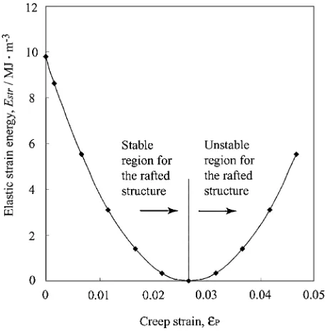
"Pexceeds 0.0266 in this case, a remarkable result is obtained concerning the stable shape of the0phase. Figure 3 shows the change in the elastic strain energy at1c=a¼0:5with increasing the creep strain gradually. From the figure, it can be said that the rafted structure becomes stable as the creep strain increases, but it becomes unstable when "P exceeds 0.0266, i.e. when "
11ð¼"
22Þ becomes a positive value.
Figure 4 shows the relation between the stable shape of the0 phase and the ratio oft1¼"11="
33.
18)When the creep strain
exists andt1 is between 0 and 1, the (001) raft is the stable
structure and the rafting phenomena occurs. However, if the creep strain increases and t1 becomes less than 0, i.e.
if "
11ð¼"22Þ becomes a positive value ("11="33 <0), the
stable orientation of the raft plane tilts, which leads to the destabilization of the rafted structure.
Based on the analysis of the elastic strain energy as shown in Figs. 2, 3 and 4, the formation and collapse processes of the rafted structure can be understood. Actually there has been a report that the stable orientation of the lamellar plane changes as the creep deformation proceeds.21)
3.2 Phase-field simulation
Simulations were performed by solving the two sets of equations, eqs. (1) and (2) numerically, using the explicit method under the periodic boundary conditions. The coef-ficients of the chemical free energy in eq. (4) were determined as W1 ¼133 and W2¼877J/mol from the
Gibbs energy curve at 1273 K calculated based on the thermodynamic database22)as shown in Fig. 1. The average
volume fraction of the0phase was set to bef
0¼0:5and the
gradient energy coefficients were chosen as f ¼s¼ 5:01015Jm2/mol. In the calculation of the elastic strain
energy, values c11 ¼250:8GPa, c12¼150:0GPa, c44¼
123:5GPa20) and "0¼ 0:0133 were used in this study. Time step t was selected to be 0.2 so as to maintain the stable solution.
Fig. 2 Change in elastic strain energy with the shape change of the0phase
as a function of1c=aas the eigenstrain changes from cubic symmetry into tetragonal symmetry. The shape of the0 phase is represented by aacin dimensions.
Fig. 3 Change in elastic strain energy with increasing the creep strain"P at the shape factor, 1c=a¼0:5. The misfit strain is set to be "0¼
[image:3.595.312.543.71.303.2] [image:3.595.54.284.72.333.2]Figure 5 shows the 2D morphological evolution of the0
phase for f0¼0:5 at 1273 K. The 0 phase is expressed as
white area. First of all, simulation was carried out using only the misfit strain without any creep strain up to t¼5000, assuming that the specimen was aged simply at this temper-ature. The result is shown in Fig. 5(a). In this case, the eigenstrain has spherical symmetry, and the cuboidal shape of the 0 phase arranged along the h100i crystallographic directions is observed due to only the anisotropic elastic interaction. Aftert¼5000, the increase of the creep strain at the constant rate d"P=dt¼6:66107 under the [001] tensile stress is introduced by assuming that the creep strain increases during creep. This creep strain relaxes the lattice mismatch in (001) plane. Thus, during t¼5000{45000 (Fig. 5(a)–(e)), it is observed that the cuboidal 0 structure gradually changes into the rafted structure and the rafted structure becomes stable in terms of the elastic strain energy. When t becomes more than 45000, i.e. when "
11ð¼"
22Þ
becomes a positive value, the rafted structure collapses and gets into wavy morphology as shown in Fig. 5(e)–(h). This means that the rafted structure becomes unstable. This is consistent with the fact that the rafted structure is stable when
"
11="33is between 0 and 1, and the rafted structure is unstable
when"
11="33 is less than 0, as mentioned in Section 3.1.
Fig. 5 Results on two-dimensional phase-field simulation showing the change of the0 phase forf
0¼0:5at 1273 K. (a)t¼5000,
(b)t¼15000, (c)t¼25000, (d)t¼35000, (e)t¼45000, (f)t¼55000, (g)t¼65000and (h)t¼75000. Time expressed here are reduced simulation time.
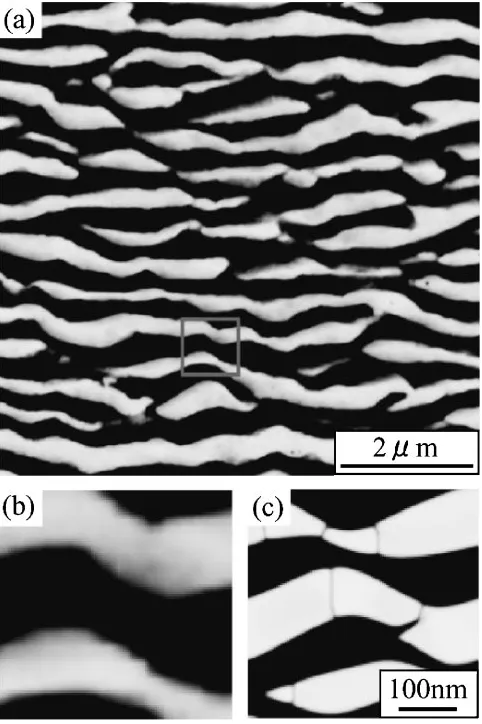
Fig. 6 Microstructure of a nickel based superalloy crept at 1193 K for 1145 h and the result of phase-field simulation in this work. (a) Microstructure of a superalloy, (b) Enlarged figure of a part in (a), and (c) A phase-field simulation result at the reduced simulation time
t¼75000. Fig. 4 Schematic interpretation of the relation between the stable shape of
the0phase and the ratio of" 11to"
[image:4.595.307.548.72.434.2] [image:4.595.113.485.551.746.2]Figure 6(a) shows a microstructure obtained from the experiment of a nickel based superalloy (Ni-14.0 mol%Cr-10.8%Al-3.8%Co-2.5%W-1.9%Ta-1.5%Ti-0.3%Mo),1)
which was designed for land-base gas-turbines, crept at 1193 K for 1145 h. A part marked by a square in Fig. 6(a) is enlarged in Fig. 6(b). Figure 6(c) shows the simulation microstructure at t¼75000 obtained in this study. The simulation result is in good agreement with the micro-structural change of practical Ni-based alloys.
4. Conclusions
The phase-field method has been adopted to simulate comprehensively from the formation to collapse process of the rafted structure in Ni-based alloys. In this work, on the basis of the elastic-plastic consideration, anisotropic relax-ation of the lattice misfit between theand0phases due to the creep strain is introduced by increasing the creep strain"P with simulation time in a constant rate. The microstructural evolution of the0 phase in the creep process is reproduced well in this simulation; the stabilization and the following destabilization of the rafted structure. This result is in good agreement with the microstructural change of practical Ni-based superalloys.
REFERENCES
1) Y. Murata, R. Hashizume, A. Yoshinari, N. Aoki, M. Morinaga and Y. Fukui:Superalloys 2000, (The Minerals, Metal & Materials Society, 2000) pp. 285–294.
2) D. D. Pearson, F. D. Lemkey and B. H. Kear:Superalloys 1980, (The Minerals, Metal & Materials Society, 1980) pp. 513–520.
3) J. K. Tien and R. P. Gamble: Metall. Trans.3(1972) 2157–2162. 4) J. K. Tien and S. M. Copley: Metall. Trans.2(1971) 215–220. 5) F. R. N. Nabarro, C. M. Cress and P. Kotschy: Acta Mater.44(1996)
3189–3198.
6) S. Socrate and D. M. Parks: Acta Metall. Mater.41(1993) 2185–2209. 7) N. Matan, D. C. Cox, C. M. F. Rae and R. C. Reed: Acta Mater.47
(1999) 2031–2045.
8) M. Ve´ron, Y. Bre´chet and F. Louchet: Scr. Mater.34(1996) 1883– 1886.
9) M. Ve´ron and P. Bastie: Acta Mater.45(1997) 3277–3282. 10) T. Ichitsubo, D. Koumoto, M. Hirao, K. Tanaka, M. Osawa, T.
Yokokawa and H. Harada: Acta Mater.51(2003) 4033–4044. 11) N. Ratel, G. Bruno, P. Bastie and T. Mori: Acta Mater.54(2006) 5087–
5093.
12) V. Vaithyanathan and L. Q. Chen: Acta Mater.50(2002) 4061–4073. 13) J. Z. Zhu, T. Wang, S. H. Zhou, Z. K. Liu and L. Q. Chen: Acta Mater.
52(2004) 833–840.
14) J. Z. Zhu, T. Wang, A. J. Ardell, S. H. Zhou, Z. K. Liu and L. Q. Chen: Acta Mater.52(2004) 2837–2845.
15) M. P. Gururajan and T. A. Abinandanan: Acta Mater.55(2007) 5015– 5026.
16) T. Koyama: The 19th Computational Mechanics Conference, (The Japan Society of Mechanical Engineers, 2006) pp. 357–358. 17) J. W. Cahn and J. E. Hilliard: J. Chem. Phys.28(1958) 258–267. 18) A. G. Khachaturyan: Theory of structural transformation in solids,
(Wiley, New York, 1983).
19) T. Mura: Micromechanics of Defects in Solids, 2nd revised ed., (Kluwer Academic, 1991).
20) Kinzoku data book, 2nd revised ed., (The Japan Inst. Metals, 1984). 21) K. Tanaka, T. Ichitsubo, K. Kishida and H. Inui: Report of the 123rd
Committee on Heat-Resisting Metal and Alloys, (Japan Society of the Promotion of Science, 2005) pp. 147–152.
22) I. Ansara, N. Dupin, H. L. Lukas and B. Sundman: J. Alloy. Compd.