1National Engineering Research Center for Equipment and Technology of Cold Strip Rolling, Yanshan University,
Qinhuangdao 066004, China
2School of Materials Science and Engineering, Tsinghua University, Beijing 100084, China
Vacuum die castings of AZ91D magnesium alloy were produced at different slow shot speeds and the correlation between density and microstructural features in the vacuum die castings were investigated. The density was measured by using Archimedes method. The microstruc-ture was analyzed with optical microscope, scanning electron microscopy and image analysis software. It was found that the partially solidified gate can be early closed-off by large-size particles at low enough slow shot speeds, which causes high levels of porosity in the vacuum die castings and thus low densities of the castings. Archimedes method is not suitable for evaluating the porosity level in the vacuum die castings. Besides the porosity levels, the densities of the vacuum die castings are related to the ESCs contents in the castings and solidification conditions in the shot sleeve at the beginning of die filling. [doi:10.2320/matertrans.M2016318]
(Received September 12, 2016; Accepted November 2, 2016; Published December 25, 2016)
Keywords: vacuum die casting, density, porosity, externally solidified crystal, AZ91D
1. Introduction
Due to the advantages of high production efficiency, high dimension accuracy and good surface quality, high-pressure die casting (HPDC) process has become one of the most com-monly used molding methods for magnesium and aluminum alloys. Currently, HPDC castings are widely used in the fields of automobile, exercise equipment, electronics, aerospace, etc.1,2)
Porosity is one of the most common defects in HPDC cast-ings, mostly coming from the trapped air in die cavity during die filling.3–5) The presence of porosity in HPDC castings is
harmful as the mechanical properties, weldability, pressure tightness and heat treatment performence are adversely af-fected.6–8) Vacuum die casting is an effective way in reducing
the porosity level in castings. By creating a lower than atmo-spheric pressure in the shot sleeve and die cavity, much less gas would be entrapped in the liquid metal during the vacuum die casting process.3)
The porosity level is one of the most important factors for evaluating the quality of HPDC castings. The traditional re-search methods for the porosity in HPDC castings are quanti-tative analysis techniques based on two-dimensional (2D) metallographic observation.9–11) Recently, three-dimensional
(3D) porosity visualization studies have been extensively car-ried out through reconstruction from montage serial 2D sec-tions12,13) or high resolution X-ray computed tomography
technology.14–17) These quantitative analysis techniques make
it possible to measure the porosity level with high accuracy, whereas their applications are limited to 2D metallographic sections or small-size specimens cut from HPDC castings.15)
To date the porosity levels in large-size HPDC castings are generally evaluated by measuring the density of the castings using Archimedes method.18–20) In this method, the density of
the castings is measured by considering the weight loss after
immerged into the liquid with certain density, such as purified water and industrial alcohol. This method has advantages of simple operation, no damage to the castings as well as low cost, and it has been widely used for evaluating the porosity level in conventional HPDC castings. The porosity level in vacuum die castings is relative low. The measuring accuracy of this method may be restrained for vacuum die castings. In the present work, vacuum die castings of AZ91D magnesium alloy were produced at different slow shot speeds. The cor-relation between density and microstructural features in the vacuum die castings was studied to examine the effectiveness of Archimedes method in evaluating the porosity level in the vacuum die castings.
2. Experimental Procedure
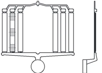
The commercial AZ91D magnesium alloy with a nominal composition given in Table 1 was used in this work. A TOYO BD-350V5 cold chamber die casting machine incorporated with a self-improved TOYO vacuum system was used for the experiments. The vacuum pressure variation in the die cavity was measured by a KEYENCE pressure sensor with the accu-racy of 0.1 kPa. Plate-shaped castings consisting of six plates with thicknesses of 6.25 mm, 3.75 mm, 1.25 mm, 2.5 mm, 5 mm and 7.5 mm from left to right were made on the ma-chine. Figure 1 shows the configuration of the castings. The six plates have the same length of 210 mm. Three slow shot speeds of 0.05 m/s, 0.10 m/s and 0.15 m/s were used in the experiments. Some other important process parameters used in the experiments are listed in Table 2, which were preset in the machine. In order to obtain relatively steady casting con-ditions, the first five shots at each slow shot speed were
dis-*
Lecturer, Yanshan University, Corresponding author, E-mail: wql_456@ 163.com
Table 1 Nominal chemical composition of AZ91D magnesium alloy (mass%).
Al Zn Mn Si Fe Cu Ni Be Mg
carded, after which another five castings were cast. A total of 15 castings (5 for each slow shot speed) were produced.
As shown in Fig. 1, specimens with the same length of 40 mm were sectioned at the two ends as well as in the middle of the plates with thickness of 3.75 mm in the produced cast-ings. According to the original positions, the specimens are named the inlet, middle and outlet parts, respectively. The densities of the specimens was measured using Archimedes method. The liquid used was absolute alcohol and the quality measurements were performed on an electronic balance with the accuracy of 0.1 mg. Then some of the specimens and gates corresponding to the plates with thickness of 3.75 mm were sectioned for microstructural examination. The sections were polished using standard metallographic techniques and etched with an acetic nitric etch. The microstructures were analyzed using light optical microscopy (LOM) and scanning electron microscopy (SEM). Measurements of gas porosity and ESCs were performed using the Micro-image Analysis & Process image analysis software at 25× and 100× magnifica-tions, respectively. At least three micrographs were analyzed for each measurement.
3. Results and Discussion
3.1 Vacuum pressure in die cavity at the beginning of die filling
After the liquid metal was ladled into the shot sleeve through the pouring hole, the plunger began to move at the preset slow shot speed. When the plunger moved past the pouring hole and sealed off the shot sleeve and die cavity, the vacuum valve was activated and a lower than atmospheric pressure was created in the die cavity. Die filling started when the liquid metal reached the gate. The die cavity were quickly filled by the liquid metal pushed by the plunger moved at the fast shot speed. Due to the violent nature of liquid metal flow during die filling, air in the die cavity tends to be entrapped in
the metal. Consequently, the vacuum pressure in the die cav-ity at the beginning of die filling has a great influence on the quality of vacuum die castings.
The measured vacuum pressure and cylinder pressure during the vacuum die casting processes at different slow shot speeds are shown in Fig. 2. P is the vacuum pressure in the die cavity at the beginning of die filling. τ represents the time at which the vacuum valve was activated and the die cavity began to be evacuated. t identifies the plunger moving time before die filling. Thus, the vacuum time Δt which indicates the duration of evacuation before die filling can be described as Δt = t − τ. As shown in Fig. 2, the variations of vacuum pressure in the die cavity against plunger moving time behave similarly at different slow shot speeds. The vacuum pressure in the die cavity drops quickly at the beginning of evacuation. As the vacuum pressure gets close to the minimum value that the vacuum system can achieve, the decline of the vacuum pressure gradually slows down and eventually stops. The ex-act values of t, Δt and P at different slow shot speeds are given in Table 3. It can be seen that t and Δt decrease dramat-ically with the increase of the slow shot speed. At the slow shot speeds of 0.05 m/s and 0.10 m/s, Δt is long enough for P to approach the minimum value. In contrast, P is still some way from the minimum value at the slow shot speeds of 0.15 m/s due to the shorter Δt.
3.2 Densities and porosity distributions
[image:2.595.311.540.68.233.2]The densities of the specimens cut from different parts of the plates with thickness of 3.75 mm from the produced vac-uum die castings are presented in Fig. 3. It is shown that the densities of the specimens from the castings produced at the slow shot of 0.05 m/s are much lower in comparison with Table 2 Some important process parameters used in die casting.
Pouring temperature (K)
Die temperature (K)
Slow shot
speed (m·s−1)speed (m·sFast shot −1)pressure (MPa)Intensification
953 453 0.15 5.0 13.7
[image:2.595.82.261.70.198.2]Fig. 2 Measured vacuum pressure and cylinder pressure variations against plunger moving time at different slow shot speeds.
Table 3 The plunger moving time before die filling, vacuum time and vac-uum pressures in the die cavity at the beginning of die filling at different slow shot speeds.
Slow shot speed
(m·s−1) t (s) ∆t (s) P (kPa)
0.05 5.68 2.80 8.75
0.10 2.99 1.23 9.74
0.15 2.16 0.78 15.34
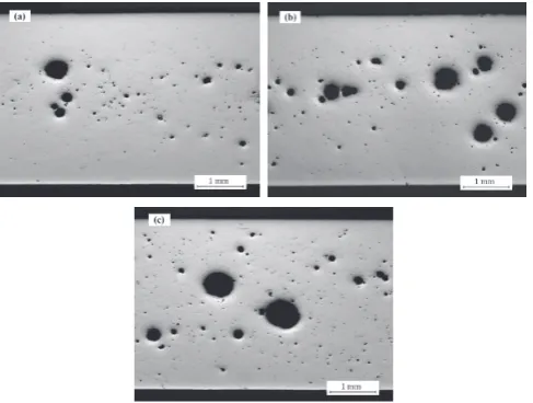
[image:2.595.45.292.289.324.2] [image:2.595.304.548.321.381.2]those produced at the slow shot of 0.10 m/s and 0.15 m/s. The specimens were sectioned in the middle to examine the porosity distributions in different parts of the plates from the castings produced at different slow shot speeds, and the mi-crostructures in the middle of the cross sections are shown in Figs. 4–6. It can be seen clearly that the specimens from the castings produced at the slow shot speed of 0.05 m/s contain much higher fractions of porosity when compared to those produced at the other two slow shot speeds. That is why the specimens from the castings produced at the slow shot of 0.05 m/s have lower densities.
A pressure level of 8.75 kPa was achieved in the die cavity at the beginning of die filling at the slow shot speed of 0.05 m/s as shown in Table 3. This is a pretty high vacuum level, and thus the entrapment of a large amount of gas is impossible during die filling. Consequently, the high porosity levels in the specimens from the castings produced at the slow shot speed of 0.05 m/s are not formed by gas entrapment.
The gates corresponding to the plates with thickness of 3.75 mm were sectioned longitudinally for microstructural
examination. It can be seen from Fig. 7 that a large-size parti-cle about 400 µm in diameter locates in the center of the gate from a vacuum die casting produced at the slow shot speed of 0.05 m/s. No similar phenomenon was observed for the other two slow shot speeds.
The large-size particle was formed in the shot sleeve. Due to the heat extraction through the sleeve interface, the primary crystals began to form at the wall after the liquid metal was poured into the shot sleeve. The plunger moving time before die filling t is also the dwell time of the liquid metal in the shot sleeve. It can be seen from Table 3 that t is much longer for the slow shot speed of 0.05 m/s in comparison with the other two slow shot speeds. Some coarse dendrites are formed due to the long dwell time of the liquid metal in the shot sleeve. The fragmentation of the coarse dendrites during moving of the plunger generates some large-size fragmented dendrites. The gate solidifies during die filling, and the partial solidification of the gate can inhibit filling and feeding of Fig. 3 Densities of the specimens cut from different parts of the plates with
thickness of 3.75 mm from the vacuum die castings produced at different slow shot speeds.
Fig. 4 Typical micrographs from the middle of the cross sections in speci-mens from the vacuum die castings produced at the slow shot speed of 0.05 m/s, showing the porosity distributions in: (a) inlet, (b) middle and
(c) outlet parts of the plates with thickness of 3.75 mm. Fig. 6mens from the vacuum die castings produced at the slow shot speed of Typical micrographs from the middle of the cross sections in speci-0.15 m/s, showing the porosity distributions in: (a) inlet, (b) middle and (c) outlet parts of the plates with thickness of 3.75 mm.
[image:3.595.55.285.67.237.2] [image:3.595.306.548.69.253.2] [image:3.595.48.292.297.481.2] [image:3.595.307.548.319.505.2]metal to the castings.21) The large-size particle shown in
Fig. 7 is actually a large-size fragmented dendrite stuck in the partially solidified gate. The partially solidified gate was early closed off by the large-size particle, resulting in improper feeding of metal to the castings. The high levels of porosity in the vacuum die castings produced at the slow shot speed of 0.05 m/s are formed due to the improper feeding.
The porosity distributions in the plates with thickness of 3.75 mm are similar for the vacuum die castings produced at the slow shot speeds of 0.10 m/s and 0.15 m/s. As shown in Figs. 5–6, the porosity levels in the inlet and outlet parts are very low and the middle parts contain significantly higher fractions of porosity. The higher porosity levels in the middle parts are caused by the type of liquid metal flow within the die cavity. In HPDC process, high gate velocities results in atom-ized metal flow within the die cavity. The first metal to enter the die strikes the far side of the die cavity and solidified im-mediately. As the liquid metal sprays into the die, it fills from the surface of the cavity inward.22) Thus, the residual gas is
finally entrapped in the middle of the die cavity, resulting in the higher porosity levels in the middle parts of the vacuum die castings. The densities of the specimens cut from different parts of the plates cannot represent the porosity levels in the corresponding parts for the vacuum die castings produced at the slow shot speeds of 0.10 m/s and 0.15 m/s. One clear ev-idence is that the inlet parts have much higher densities when compared to the outlet parts as shown in Fig. 3, even though the porosity levels in both of the two parts are very low.
3.3 Microstructural features
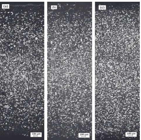
Figures 8–9 show the typical etched micrographs from the middle of the cross sections in the specimens cut from differ-ent parts of the plates with thickness of 3.75 mm from the vacuum die castings produced at the slow shot speeds of 0.10 m/s and 0.15 m/s, respectively. Figure 10 shows a typi-cal higher magnified micrograph from the cross section in the specimen cut from the middle part of a plate from a vacuum die casting produced at the slow shot speed of 0.15 m/s. The white phase in the micrograph is α-Mg containing externally solidified crystals (ESCs) formed in the shot sleeve and sec-ondary α-Mg particles formed in the die cavity. Due to the high cooling rate of the liquid metal after being sprayed into the die cavity, the secondary α-Mg particles formed in the die cavity are generally smaller than the ESCs. In the measure-ment the ones larger than 7 µm in diameter were taken as ESCs. The measured average area fractions of ESCs in
differ-ent parts of the plates from the vacuum die castings produced at the slow shot speeds of 0.10 m/s and 0.15 m/s are listed in Table 4. It can be seen that the average area fractions of ESCs in different parts of the plates from the castings produced at the slow shot speed of 0.10 m/s are much higher when com-pared to the corresponding parts of the plates from the cast-ings produced at the slow shot speed of 0.15 m/s. This is due to the longer dwell time of the liquid metal in the shot sleeve, Fig. 8 Typical micrographs from the middle of the cross sections in
speci-mens from the vacuum die castings produced at the slow shot speed of 0.10 m/s, showing the ESCs distributions in: (a) inlet, (b) middle and (c) outlet parts of the plates with thickness of 3.75 mm.
[image:4.595.55.284.69.162.2]i.e. the plunger moving time before die filling t, at the slow shot speed of 0.10 m/s as shown in Table 3. For both of the slow shot speeds, the outlet parts of the plates contain the highest fractions of ESCs, and the fractions of ESCs in the middle parts are little higher in comparison with the inlet parts.
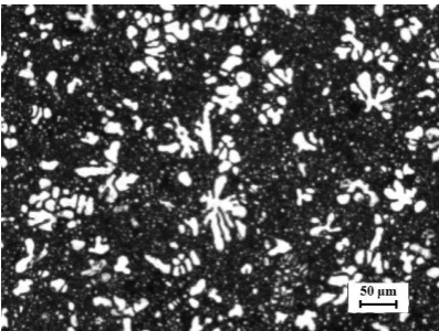
Figure 11 shows the microstructural features in the vacuum die castings, which contain ESCs, pores and fine structures consisting of secondary α-Mg particles (α) and net-like di-vorced eutectics distributed in the grain boundaries. The dis-crete β-Mg17Al12 particles (β) are surrounded by the
supersat-urated α-Mg solution (α′) in the divorced eutectics. Figure 12 shows the contents of the ESCs and secondary α-Mg particle
marked by the arrows shown in Fig. 11. It can be seen that the Al content in the ESCs is about 3.5 mass%, much lower than the nominal Al content in AZ91D alloy. The Al content in the secondary α-Mg particle formed in the die cavity is a little higher when compared to the ESCs. The other main alloying elements Zn and Mn have not been detected. The results demonstrate that the main alloying elements in AZ91D alloy are aggregated to the grain boundaries during solidification in the die cavity, at which the divorced eutectics form.
3.4 Correlation between density and microstructural features in vacuum die castings
As mentioned above, some primary crystals have been formed at the beginning of die filling. Assuming that the re-maining liquid metal in the shot sleeve at the beginning of die filling is removed and solidified alone, according to mass conservation the density of the imaginary formed solid can be given by:
[image:5.595.69.268.69.219.2]ρr=(ρAZ91D−ρ¯sfs)/(1−fs) (1) where ρAZ91D is the density of AZ91D alloy, ρ¯s is the average density of primary crystals formed in the shot sleeve at the beginning of die filling, fs = Vs/(Vs + Vr) represents the solid-ification condition of the liquid metal in the shot sleeve at the beginning of die filling, with Vs being the volume of primary Fig. 11 Typical SEM micrograph in the specimen cut from the middle part
[image:5.595.315.534.70.434.2]of the plate with thickness of 3.75 mm from a vacuum die casting pro-duced at the slow shot speed of 0.15 m/s showing the microstructural features in the castings.
Fig. 12 EDS spectra of the ESCs (a) and secondary α-Mg particle (b) marked by the arrows shown in Fig. 11.
Fig. 10 Typical etched microstructure in the specimen cut from the middle part of the plate with thickness of 3.75 mm from a vacuum die casting produced at the slow shot speed of 0.15 m/s.
Table 4 Measured average area fractions of ESCs in different parts of the plates with thickness of 3.75 mm from the vacuum die castings produced at different slow shot speeds.
Slow shot speed (m·s−1)
ESCs fractions (%)
Inlet Middle Outlet
0.10 21.42 22.68 28.48
[image:5.595.68.269.390.554.2]Fig. 11, should be equal to ρr, since all the liquid metal
trans-ferred into the die cavity has been solidified into the fine structures. Considering the characteristics of high speed and high pressure for the HPDC process, the liquid metal and floating crystals are fully mixed during die filling. For each of the specimens cut from a certain vacuum die casting, the fine structures solidified from the liquid metal should have a same local average density ρr, and the local average density of
ESCs should be equal to the average density of ESCs in the entire vacuum die casting ρ¯ESCs . Consequently, the densities of the specimens cut from different parts of the plates from the vacuum die castings can be calculated by:
ρ=ρrfres+ρ¯ESCsfESCs (2)
with fres = 1 − fESCs − fpores where fres represents the volume
fraction of the fine structures in the specimens. fESCs and fpores
are the volume fractions of the ESCs and porsity in the spec-imens, respectively.
According to the Mg-Al phase diagram,24) the Al content in
the solid phase at phase equilibria between solid and molten Mg-9 mass%Al alloy is about 3 mass%. During the growth of the solid, a solute enriched zone can be quickly established ahead of the growing interface due to the solute rejection at the growing interface. Dendrites and equiaxed crystals can be formed in the solute enriched zone due to constitutional un-dercooling. As shown in Table 3, t is no longer than 3 seconds at the slow shot speeds of 0.10 m/s and 0.15 m/s, much shorter when compared to that at the low shot speed of 0.05 m/s. Due to the short dwell time of liquid metal in the shot sleeve, the solid fraction in the short sleeve before die filling cannot be very high. This indicates that the solute en-riched zone will keep relative stable during the growth of the solid, and thus the compositions of the primary crystals solid-ified in the shot sleeve won t vary much. The ESCs are from the fragmented dendrites and equiaxed crystals formed in the shot sleeve. As part of the primary crystals, the ESCs have similar compositions to the primary crystals. The average density of the ESCs is close to that of the primary crystals solidified in the shot sleeve:
¯
ρESCs≈ρ¯s (3)
Taking eqs. (1) and (3) into eq. (2), one has:
ρ=(ρAZ91D−ρ¯ESCsfs)(1−fpores−fESCs)/(1−fs)+ρ¯ESCsfESCs (4) Equation (4) demonstrates that, besides the porosity levels, the densities of the specimens depend on the ESCs contents in the specimens and solidification conditions in the shot
parts and the outlet parts in the case that the porosity levels in middle parts are significantly higher in comparison with the outlet parts as shown in Figs. 5–6. The longer dwell time of the liquid metal in the shot sleeve results in a higher solid fraction before die filling at the slow shot speed of 0.10 m/s, which causes that the corresponding parts of the plates from the castings produced at the two slow shot speeds have close densities, though the ESCs content in different parts of the plates from the castings produced at the slow shot of 0.10 m/s are much higher when compared to the corresponding parts of the plates from the castings produced at the slow shot of 0.15 m/s.
From eq. (4) one has:
fs=[ρAZ91D(1−fpores−fESCs)+ρ¯ESCsfESCs −ρ]/( ¯ρESCs(1−fpores)−ρ)
(5)
As mentioned above, fs represents the solidification
condi-tion in the shot sleeve at the beginning of die filling, and it can hardly be directly measured. According to eq. (5), by just tak-ing a specimen from any part of the vacuum die casttak-ings, after measuring the density of the specimen, the volume fractions of the ESCs and porosity together with the average density of ESCs in the specimen, the solidification condition in the shot sleeve at the beginning of die filling can be estimated.
4. Conclusions
(1) The partially solidified gate can be early closed off by large-size particles when the slow shot speed is low enough. The improper feeding causes high levels of porosity in the vacuum die castings, resulting in the low densities of the cast-ings.
(2) The porosity distributions in the plates with thickness of 3.75 mm are similar for the vacuum die castings produced at the slow shot speeds of 0.10 m/s and 0.15 m/s. The poros-ity levels in the inlet and outlet parts are very low. The middle parts contain significantly higher fractions of porosity when compared to the inlet and outlet parts.
(3) The vacuum die castings produced at the slow shot speed of 0.10 m/s have much higher ESCs contents when compared to the castings produced at the slow shot speed of 0.15 m/s. The ESCs distributions in the plates with thickness of 3.75 mm from the vacuum die castings are similar for the slow shot speeds of 0.10 m/s and 0.15 m/s. The outlet parts of the plates contain the highest fractions of ESCs, and the fractions of ESCs in the middle parts are little higher in com-parison with the inlet parts.
The authors gratefully acknowledge the financial supports from the National Natural Science Foundation of China (51275446), Natural Science Foundation of Hebei Province of China (E2016203492) and Hebei Provincial Foundation for Returned Scholars (C2013005012).
REFERENCES
1) H. Gjestland and H. Westengen: Adv. Eng. Mater. 9 (2007) 769–776. 2) J. Collot: Mater. Manuf. Process. 16 (2001) 595–617.
3) P. Homayonifar, R. Babaei, E. Attar, S. Shahinfar and P. Davami: Int. J. Adv. Manuf. Technol. 39 (2008) 219–228.
4) M. Cross, K. Pericleous, T.N. Croft, D. McBride, J.A. Lawrence and A.J. Williams: Metall. Mater. Trans., B 37 (2006) 879–885.
5) Q.L. Wang and S.M. Xiong: Trans. Nonferrous Met. Soc. China 24 (2014) 3051–3059.
6) V.D. Tsoukalas: Int. J. Cast. Metals Res. 15 (2003) 581–588. 7) X.P. Niu, B.H. Hu, I. Pinwill and H. Li: J. Mater. Process. Technol. 105
(2000) 119–127.
13) S.G. Lee and A.M. Gokhale: Scr. Mater. 56 (2007) 501–504. 14) M. Felberbaum and M. Rappaz: Acta Mater. 59 (2011) 6849–6860. 15) Q. Wan, H.D. Zhao and C. Zou: Acta Metall. Sin. 49 (2013) 284–290. 16) X. LI, S.M. Xiong and Z. Guo: Mater. Sci. Eng. A 633 (2015) 35–41. 17) X. LI, S.M. Xiong and Z. Guo: J. Mater. Sci. Technol. 32 (2016) 54–61. 18) J.H. Forsmark, J. Boileau, D. Houston and R. Cooper: Int. J. Metalcast.
6 (2012) 15–26.
19) D. Rodrigo: Characteristic microstructural features of die cast magne-sium alloys, Word of Die Casting: 20th International Die Casting Con-gress and Exposition, (NADCA, 1999).
20) H. Mao: Microstructural characteristics of die cast AZ91D and AM60 magnesium alloys, SAE Technical Paper #1999-01-0928, (SAE, War-rendale, PA, 1999).
21) X.P. Niu, K.K. Tong, B.H. Hu and I. Pinwill: Int. J. Cast Metals Res. 11 (1998) 105–112.
22) E.J. Vinarcik: Adv. Mater. Process. 159 (2001) 49–50.
23) H.I. Laukli, C.M. Gourlay and A.K. Dahle: Metall. Mater. Trans., A 36 (2005) 805–818.