Severe Plastic Deformation of Polymers
V. Beloshenko
1, Iu. Vozniak
2, Y. Beygelzimer
1, Y. Estrin
3,4and R. Kulagin
51Donetsk Institute for Physics and Engineering named after A.A. Galkin, National Academy of Sciences of Ukraine,
pr. Nauki 46, Kyiv, Ukraine
2Centre of Molecular and Macromolecular Studies, Polish Academy of Sciences, Sienkiewicza Street, 112, Lodz, Poland 3Department of Materials Science and Engineering, Monash University, Clayton 3800, Australia
4Department of Mechanical Engineering, The University of Western Australia, Crawley 6009, Australia 5Institute of Nanotechnology, Karlsruhe Institute of Technology, Eggenstein-Leopoldshafen 76344, Germany
Severe plastic deformation (SPD) has come to the fore over the last decades as a potent way to improve the mechanical and physical properties of metallic materials. The use of such techniques for polymers has a long history and can be proud of its significant achievements, but they are less familiar to the metal research community. This review provides insights in the use of SPD techniques to modify the microstructure and properties of polymers and summarizes the salient results obtained in this area. It is hoped that this exposé will be of interest to the broader materials community, beyond the borders of polymer research. [doi:10.2320/matertrans.MF201912]
(Received January 30, 2019; Accepted March 18, 2019; Published June 25, 2019)
Keywords: severe plastic deformation, polymers, structure-property relationships
1. Introduction
Studies of the effect of shear under high pressure on polymers have a long history, yet they are less known to researchers working in the area of severe plastic deformation (SPD) of metals. This is perhaps understandable, as the metals and polymer communities hardly interact, and most articles on the SPD of polymers appear in specialised journals dedicated to that discipline. The primary aim of this review is to familiarise researchers working on SPD of metallic materials with the progress achieved in the cognate, yet somewhat distant, discipline of SPD-related polymer research. It is the authors’ hope that the effects and phenomena found in the realm of polymers will be of relevance and interest to the SPD community at large.
2. Structure and Properties of Polymer Materials
Modified by SPD
The SPD techniques used to modify the structure of polymer materials include High Pressure Torsion (HPT),1,2)
Equal Channel Angular Extrusion (ECAE),3,4)Equal Channel
Multi-Angular Extrusion (ECMAE),5,6) T-shape Equal
Channel Extrusion (TECE),7) Twist Extrusion (TE),8) and
Planar Twist Extrusion (PTE).9)Strictly speaking, the use of
the notion of‘extrusion’in this context is not correct, and a more appropriate term ‘pressing’ should be used instead, cf. Ref. 10). However, for historical reasons, the former term has been accepted by the polymer community, and that is why it is adopted in this review. Unlike the conventional methods of processing of polymers under high pressure, such as die extrusion, rolling, and drawing under pressure, the SPD techniques enable accumulation of a large plastic strain, while retaining the shape and dimensions of an initial billet. The changes produced at various structural levels are determined by the nature of the process itself as well as by the process conditions, such as pressure, temperature and deformation rate.
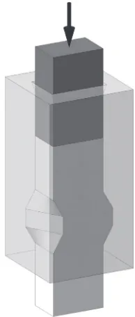
2.1 High pressure torsion
A vivid interest in the HPT-induced evolution of the structure and the properties of polymers (Fig. 1) arouse in the 19701980s, when seminal fundamental results1129) were obtained. Large shear strains imposed on a polymer under high pressure give rise to a relatively rapid destruction of the inner make up of a polymer at various structural levels. This is accompanied with its amorphization, orientation order formation, re-structuring of the crystal lattice and in some cases substantial changes in the conformation of polymeric chains. The greatest effect is attained at the rim of an HPT sample for the anvil rotation of about 100°.12,19) The
magnitude of HPT-induced re-structuring depends on the type of the polymer processed.12,14,17,18)
A substantial reduction of the molecular mass of homopolymers stemming from mechano-chemical destruc-tion leads to a deterioration of their physical and mechanical.11,19)By contrast, in the case of polymer mixtures the properties can be improved by HPT, owing to a pronounced comminution of phases, their more uniform distribution and the formation of new crystal structures (co-crystallites).14) The specifics of the mechano-chemical
destruction process are dictated by the type of the polymer
Fig. 1 Schematics of the HPT process. Special Issue on Severe Plastic Deformation for Nanomaterials with Advanced Functionality
[image:1.595.376.475.627.768.2]and the HPT process parameters. Thus, for polypropylene (PP) intensive destruction sets in at pressures in excess of 0.5 GPa, while for polyethylene (PE) this occurs for pressures above 1 GPa.19) For a PP-ethylene propylene rubber
composite, an increase of strength and elongation at break is observed when the anvil rotation angle is raised up to 400°. However, a drop in these characteristics occurs upon further increase of the anvil angle.18,19)
HPT of hard monomers promotes the formation of macromolecular compounds.16)The degree of polymerisation increases with growing pressure, process temperature, and the anvil rotation angle, i.e. the magnitude of shear strain. Polymers synthesised under HPT exhibit a bimodal molecular mass distribution, which is associated with the dislocation motion in two different crystallographic directions or the occurrence of two distinct types of dislocations®having edge or screw characteristics.16) A polymer formed in such
conditions differs from polymers obtained in an isotropic medium, e.g. by solid or liquid state polymerisation, in terms of its structure and properties.
Shear deformation under high pressure has an effect on the electrical conductivity of doped polymers.20)The effect stems from changes in the electron zone structure of the polymer matrix and the particles of the doping agent. Specifically, the gap width of such conjugated systems is diminished by HPT. As a result, the band structure of the material in the vicinity of interfaces between the polymer and the dopant particles differs from that obtained under the ambient pressure. During the HPT process, electrons may be injected from the dopant particles, which are in the conductance band, i.e. the metallic state, into the polymer matrix, thus increasing the conductivity of the material.
HPT can also lead to homogenisation of blends of thermodynamically incompatible polymers, as was demon-strated for PP-PE and PP-ethylene propylene rubber mixtures.15,18,19) This is associated with mutual dissolution of amorphous regions of the constituents of the polymer blend by HPT, which cannot be achieved by mixing in the melt. Gradual increase of interaction between the phases due to plasticflow during HPT causes a decrease of the size of the dispersion phase particles, which improves the physical and mechanical properties of the composite. Addition of inorganicfillers, such as aerosil, ash, and asbestos, enhances homogeneity of the mix and makes it possible to produce blends with the same glass transition temperature at lower pressures.18) It should be noted, however, that polymer
mixtures that underwent HPT processing are not thermally stable and are prone to phase separation and heterogenization upon annealing.
Despite the efficacy of deformation by shear under high pressure as a method for structure modification of polymers, its practical applicability is limited by the small volume of the material that can be processed by conventional HPT (5 10 mg for the anvil area of 1 cm2). An area where this limitation is immaterial and HPT can be a process of choice in its own right is microfabrication, as highlighted in a recent publication.30) It should be mentioned that a method of continuous HPT developed recently31) brings this kind of
processing closer to large-scale manufacturing. In addition, HPT can be used as a potent tool for modelling the processes
underlying ECAE or ECMAE®the laboratory-scale tech-niques that are more viable for upscaling than HPT itself. The suitability of HPT for that purpose owes to the great variability of pressures and shear strains it provides and commonalities in the physical mechanisms underlying these SPD processes.32)
2.2 Equal channel angular extrusion
Studies into equal channel angular pressing of polymers commenced some two decades ago.33) The ECAE process, sketched in Fig. 2, is used to create an oriented micro-structure of a polymer thus enabling manufacture of products with high strength characteristics. Unlike the conventional techniques of solid-state extrusion of polymers including plunger and hydrostatic extrusion,34) which bring about a
decrease of the cross-sectional dimensions of the billet, molecular alignment by ECAE occurs without changes in the billet shape. This opens up new possibilities to control the microstructural state of a polymer by suitable choice of the ECAE tool geometry, the deformation route, and the process parameters.
Studies conducted on polymer materials with various inner architecture have revealed a number of regularities regarding their altered structure induced by ECAE.3569) In the case of polymers that crystallise, the process leads to a transformation of the initial spherulite structure to a
fibrillar one, with a mono- or bi-modal orientation of the
fibrils.5,3440,46,4850,54)The character and degree of molecular alignment are governed by the cumulative strain, temperature and the deformation route.5)
The greatest effect in terms of property improvement of such materials is achieved at elevated process temperatures. As demonstrated for poly(DL-lactide),50) ECAE at 75°C
increases the melting temperature Tm and the bending
modulus of elasticity Eb and also alters the character of
fracture from the brittle to the ductile one. While the non-deformed material exhibits Eb=83 MPa, this characteristic
is raised to 179 MPa by two ECAP passes according to route A (in which the billet is not rotated between the
[image:2.595.378.478.558.770.2]passes). For low temperatures and high speeds, ECAE is accompanied with undesired stick-slip, which is detrimental to the quality of the product.69)According to literature data,63)
the temperature interval recommended for ECAP processing of semicrystalline polymers is (0.800.95)Tm.
The optical properties of semicrystalline polymers are affected by ECAP in a positive way. In particular, the light transmission coefficient of PP was found to increase by a factor of 1.2 due to ECAE processing. The magnitude of the effect increases with strain.46)It is associated with a decrease in the crystallite size and their alignment by ECAE.
In the case of amorphous and glassy polymers, ECAE causes molecular alignment without a loss of transparency of the polymer.36,39,42,56) The mechanical properties of
Poly(methyl methacrylate) (PMMA) exhibit a slight increase of elastic stiffness and strength, while retaining high ductility values after two passes of Route A ECAE at 120°C.42)Such
properties as crack resistance and impact fracture toughness of these classes of polymers are influenced by ECAE very significantly.36,39,42) For example, ECAE-processed PMMA shows values of the crack propagation energy and impact fracture toughness that are, respectively, 4.5 and 2.8 times higher than for the initial material.42) For amorphous polymers, there is also an optimal process temperature window (0.75«0.15)Tg where Tg is the glass transition
temperature.63)
Short fibre composite materials can also be modified by ECAE which enables control of the angle of preferential alignment of the fibres and their length.41) Below a certain
criticalfibre length, the efficacy offibre fragmentation drops precipitously. As an example, the critical fibre length for a polyacetate plastic with partially crystallised structure containing 13 mass% glass fibres was found to be about 100 µm.41)
ECAE can generate shear stresses that are sufficient for substantial deformation of both the polymer matrix and the agglomerated filler particles. An example of a PP-montmorillonite (MMT) composite considered in Ref. 59) demonstrates that a single pass of ECAE causes agglom-erated particles of MMT to assume a rod-like configuration with an aspect ratio (i.e. the ratio of length to diameter) of 510. A second pass of Route A ECAE promotes further transformation of rod-shaped MMT particles to needle-like ones, particularly nano-layered ones, which then get finely dispersed in the PP matrix, which leads to an appreciable strengthening of the latter.
ECAE is efficient in structure modification of polymer blends, including those with a weak interaction between the constituent phases, as is the case with the mixtures of polypropylene and high-density polyethylene (PPHDPE).60) It was established that this process enables strong cohesion due to increased contact area owing to high degree of dispersion and shape transformation of HDPE particles from spherical to strip-like morphology.
Another area where ECAE can be employed successfully is consolidation of semicrystalline polymer powders to monolithic billets with a high density of chain entanglements and small size crystallites.52,66) Subsequent thermal,
chemi-cal, or radiation treatment promotes consolidation by creating additional bonds between polymer chains. The result is a
polymer with enhanced strength and ductility, but a lower degree of crystallinity and a melting temperature falling below that of the initial polymer. In this way, it becomes possible to produce articles from natural polymers whose density and mechanical properties are comparable with those of synthetic polymers.53,55)Thus, three-point bending testing of samples obtained by ECAE of wheat starch powder returned the values of ultimate strength (35 MPa) and the Young’s modulus (923 MPa), which are pretty high for this kind of material. For wheat gluten, the respective values (28 MPa and 1044 MPa) were in a similar range.53)
The largest number of passes (four) was reached for ECAE of low-density polyethylene. In most cases one to two passes were used.63)The number of passes is limited by two factors:
warping of billets after each pass and the requirement of maintaining a stable billet temperature throughout the process. This makes it difficult to accumulate large strain, which puts limitations on the efficacy of ECAE in modifying a polymer’s microstructure.
2.3 Equal channel multi-angular extrusion
[image:3.595.383.470.549.771.2]As distinct from ECAE, the various ECMAE routes (Fig. 3)7088) are realised by rotating the operating die channels about a vertical axis.6) In this process the billet stays within a die channel, and in this way undesirable cooling and subsequent re-heating to the prescribed extrusion temperature are avoided. The problem of billet bending (rather than shearing) that may occur under ECAE does not arise for ECMAE. Besides, ECMAE makes it possible to change the position of the shear plane by combining different deformation routes and to realise some routes that are not possible in the case of ECAE.
ECMAE induces biaxially oriented structures with two types of microfibrils with differ in terms of the level of perfection of crystallites.73,76,78) One type is characterised by a large number of crystallites containing double or triple folds, i.e. straight chain segments traversing two or three lamellae with transcrystalline layers between them.
fibrils of the second type practically do not have crystalline formations with straight parts of macromolecules that would traverse neighbouring crystalites.79)
The best combination of mechanical properties is achieved by using Route D+C of ECMAE for the largest possible magnitude of shear strain.78)Details of this processing route are given in Ref. 78). Not only ECMAE-processed polymers (HDPE, polyamide 6 (PA-6), polytetrafluorethylene (PTFE), polyoxymethylene (POM)) exhibit a spectacular increase of microhardness, but they also retain their ductility at a level of the initial material, cf. Table 1. The magnitude of the effect depends on the chemical composition of the polymer, its molecular mass and morphology. Of great importance is the right choice of the temperature and the process rate. The recommended temperature and deformation rate ranges are close to those for polymer forming by conventional solid-state extrusion.
ECMAE-modified semicrystalline polymers exhibit a biaxial invar effect that occurs in a broad temperature range.75)It manifests itself in very low values of the thermal
expansion coefficient ¡ for longitudinal and transverse directions. The magnitude of ¡ obtained is by far smaller than that for non-deformed polymers and is close to the values observed for invar alloys, cf. Table 2.
When processed by ECMAE, amorphous glassy polymers change their microhardness, Young’s modulus, ultimate tensile strength, and fracture toughness. Typically, these characteristics are increased by a factor of 1.21.5.81)A slight
increase in the density of the material and its ductility also occurs. The magnitude of the changes depends on the deformation route chosen and the shear strain reached. According to the results of differential scanning calorimetry and scanning electron microscopy, the main mechanisms underlying these effects are the formation of elongated,
energetically favourable G-conformers, enhancement of intermolecular interaction, and the emergence of a network of oriented macromolecules that obstructs crack develop-ment.81)
ECMAE is a process enabling the occurrence of an reinforcing effect in polymer nanocomposites.82,84,87) The attendant mechanical strengthening is associated with a significant modification of the morphology of the nanofiller and structural transformation of the polymer matrix, including molecular alignment, increase of crystallinity, formation of oriented crystallites with lower level of imperfections. Composites based on polyolefines with layered nanosilicates and carbon nanoplatelets or nanotubes show degradation of large agglomerates of nanofillers and the formation of layers comprising several individual nano-particles. The resulting increase of the specific contact area between the nanofiller and the polymer matrix gives rise to a stronger interaction between the phases and promotes activation of the polymer chain orientation induced by the orientation of the nanofiller. The greatest reinforcing effect is attained when a polymer matrix with a high molecular stretching ability is combined with afiller with a high aspect ratio of the particles. The magnitude of the effect is determined by the concentration of the filler and the cumulative plastic strain. For the systems mentioned above, ECMAE enabled an appreciable increase of ductility combined with some moderate improvement of elastic stiffness and strength, produced an invar effect, and gave rise to better thermal stability of the composites.82,84,87)
The effect of ECMAE on electrically conducting polymer composites consists in enhancement of the conductivity without causing anisotropy.87) Increased electrical
conduc-tivity is a result of the occurrence of a specific spatial arrangement of thefillers that form a conducting 3D-network. An interesting area of application of ECMAE is in creating novel hybrid polymer materials based on fibrous fillers or armour filaments, which are formed within the polymer matrix in situ, as a result of the extrusion process itself.85) The latter show particularly good cohesion with the matrix. This distinguishes such in situ filaments from ready-made organic or inorganic fibres which have lesser cohesion with the matrix material. Through control of the orientation of thein situfilaments or added ready-madefibres (particularly through the formation of their biaxial alignment) a network of reinforcement agents can be produced, which leads to strengthening of the polymer material.
[image:4.595.49.291.108.203.2]ECMAE is also of interest as a technique for producing antifriction polymer materials with superior wear resistance,
Table 1 Effect of ECMAE on the mechanical properties (Young’s modulus E, stress at-break·b, and strain at break,¾b) of some polymers in tension (initial/ECMAE-processed).
[image:4.595.121.477.689.783.2]higher admissible contact pressure and good thermal resistance. For example, it was shown for PA-683) that this
kind of solid-state processing leads to a decrease of the coefficient of friction of the polymer by some 1520%. At the same time, the linear wear intensity in the stress range of 1.752.75 MPa drop by three orders of magnitude. The low values of the linear wear intensity are also observed at elevated temperatures. In addition, the admissible in-service pressure is increased by a factor in excess of two.
The efficacy of ECMAE can be improved by combining it with other deformation processes.67,68,70)A further possibility is to combine ECMAE with electron beam irradiation.86)
Specifically, in a sequential solid-state extrusion through a conical nozzle followed by ECMAE, a fibrillar structure formed in thefirst step gets fragmented in the second one, in which thefibrils are partially rotated.74)This leads to a duplex
structure consisting of stretched randomly orientedfibril-like formations up to 10 nm in diameter and 100150 nm in length, as well as some 1020 nm sized globules. It is similar to the structure of a composite that contains randomly oriented fibrils in its polymer matrix, which provides a combination of high strength and ductility. The fibril-like entities oriented in different directions reduce anisotropy of properties. Electron beam irradiation produces further strengthening of the fibrillar structure developed under ECMAE. The effect occurs due to the formation of a network of chemical nodes both in the crystalline and the amorphous phases and to chemical crystallisation.2) In the case of
radiation-strengthening polymers, such as HDPE and PA-6 irradiation with an absorption dose in the range of 10 to 80 kGy enhances the thermal stability as well as elastic and strength characteristics, while retaining low values of the thermal expansion coefficient. Even radiation-softening polymers, e.g. PTFE, that underwent ECMAE exhibit strength levels that are higher than those of the non-irradiated material.86)
A comparison of the efficacy and the potential of ECAE and ECMAE shows that the latter SPD technique is to be preferred as a method for structure modification of polymer materials of various kinds. The ECMAE-induced changes at different levels of their structural make-up can lead to improved physical and mechanical characteristics and to a qualitatively new property profile of the polymers.
2.4 T-shape equal channel extrusion
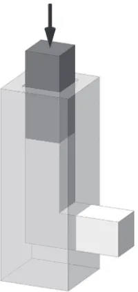
The principle behind T-shape equal channel extrusion (TECE) is illustrated in Fig. 4. A billet is pressed from one channel into the other, which has the same cross-section and intersects the first channel rectangularly. The channels have the shape of the letter “T”, from which this process derives its name.7) A distinct difference of TECE from ECAE and ECMAE is that, in addition to shear deformation, TECE is accompanied with a marked elongation of the structural elements of the material.7) This results in a structure of semicrystalline polymers that is aligned with the deformation axis of the billet, which is the cause of a strengthening effect in this direction, cf. Table 3. The magnitude of the effect is much smaller than for die extrusion,34) however. The
microhardness distribution over a cross-section of an extrudate is dome-shaped, with the apex at the middle of
the cross-section, i.e. at the axis of the billet.7) This non-uniformity of microhardness is somewhat reduced with increased process temperature.
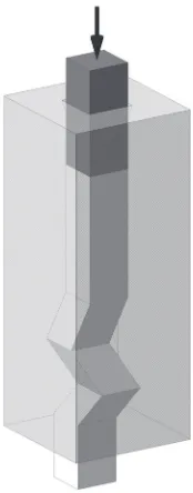
2.5 Twist extrusion
Studies conducted on semicrystalline polymers have shown7) that processing by twist extrusion (TE), Fig. 5,
leads to a pronounced change of properties, with a characteristic variation across a billet cross-section. Figure 6 displays the distribution of microhardness over a longitudinal and a transverse cross-section of an extruded billet of PA-6
[image:5.595.373.474.70.226.2]Fig. 4 Schematics of the TECE process.
Table 3 Effect of TE on the mechanical properties of selected polymers in compression (initial/TE-processed). Here·ydenotes the yield strength.
[image:5.595.303.550.284.620.2]for several process temperatures. These results correlate with the data on the material density, which show its growth from the centre to the periphery of the extruded billet.70)Structural
modification produced by TE is manifested in the behaviour of the relative elongation with the heating of the deformed samples. The diagonal length normalised with respect to its initial value, l/l0, behaves in the same way as for the material
processed by Route C ECMAE.5) Accumulation of strain by cyclic, repetitive processing (without cooling the billet) results in an increase of microhardness H and the occurrence of plateaus with the largest values of H near the rim of the extruded billets.5)
It follows that TE of semicrystalline polymers can be regarded as a method for producing a pronounced gradient in the properties over a cross-section of a rod-like billet. The magnitude of the effect can be controlled by varying the process temperature and the cumulative strain. The combi-nation of a hard outer‘sheath’and a softer, ductile interior of a rod is of interest with regard to manufacture of products that require such a property profile, e.g. bone implant materials.
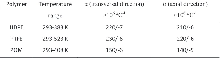
2.6 Planar twist extrusion
Planar twist extrusion (PTE) tests were conducted on PA-6 and HDPE. They established that, unlike TE, the PTE process, Fig. 7, produces a reasonably uniform microhard-ness distribution over a (rectangular) cross-section of a polymer billet.89) It resembles that for metals89) and is
represented by elongated isolines of H along the short side of the cross-section. However, the H-values in the middle zone exceeds those at the periphery. The average value of H in a
longitudinal section is higher than in a transversal one. Both are increased if a back-pressure Pb is applied and/or the
extrusion rate Veis decreased.89)The mechanical properties
of PA-6 and HDPE processed by PTE, measured in tension (Table 4) provide convincing evidence for a substantial strengthening effect combined with an acceptable ductility. A minor drop of strength characteristics (at the unchanged level of ductility and density µ) upon a five-fold increase of Ve
(a) (b)
Fig. 6 Distribution of microhardness along the diagonallof a transverse section (a) and lengthLof a longitudinal section (b) of an extruded billet of PA-6 processed by TE. Process temperature: 373 K (1), 423 K (2), 448 K (3), 483 K (4). The microhardness of the polymer in the initial state is shown by a horizontal dotted line in (a).
[image:6.595.115.480.72.205.2]Fig. 7 Schematics of the PTE process.
[image:6.595.377.474.261.489.2] [image:6.595.114.483.673.783.2]suggests that Ve=3 mm/s is a reasonable choice of the
processing rate. High productivity potential of PTE is ensured by the possibility of processing of long products in a semi-continuous regime.
3. Modelling of SPD Processing of Polymers
A detailed review of the state-of-the-art modelling of SPD was given in Ref. 90). However, the review dealt mainly with metallic materials. As polymers are different from metals in their structure and rheological properties, other mechanisms govern their mechanics and physics, which requires different approaches to modelling their SPD processing. In particular, high strain rate sensitivity of theflow stress of polymers leads to broadening of the shear zone and greater stability of plastic deformation, as was demonstrated in Ref. 91) for the case of HPT. Large elastic deformation and high strain rate sensitivity that are characteristic of polymers may cause a switch of the deformation mode from simple shear to pure shear, as will be shown towards the end of this section.
At present, there is a great need for work on mathematical modelling of SPD processes that would consider the specifics of the mechanics and physics of polymers. As a matter of fact, all the necessary prerequisites for that are in place. Literature contains a large number of publications on deformation modelling for large plastic strains, as well as the structure and properties of polymer materials. Among others, one should mention articles,9297) which provide concise reviews and original results on the mechanics and micromechanics of semicrystalline and amorphous polymers. Professional software packages based on the finite element methods (FEM) offer the provision for using various visco-elastic-plastic models and can thus account for the specifics of the mechanics of polymers. Moreover, the popular VPSC code that is well-suited for modelling of SPD of metals has already been extended to polymer materials.98)In some cases, rather simple methods and models accounting for just the plastic or viscoplastic component of the polymer rheology can be employed to model SPD of polymers, notably for calculating the force-related quantities. The noteworthy pertinent works are Refs. 99, 100), which are based on the rigid block method, as well Refs. 101, 102), where theflow lines for the ECAE process were studied with the aid of the viscousfluid model.
Let us consider modelling of the ECAE of polymers as a representative example. For process optimisation it is necessary to know how the plastic strain is distributed within the processed billet. The authors of Refs. 103105) developed models that make it possible to analyse the accumulation of plastic strain under ECAE. The underlying assumption is that the material is ideally plastic, i.e. the elastic component of strain is neglected. This may not be a valid assumption for polymers, as the elastic strain therein may be quite substantial. Still, the complexity of the ECAE process tends to justify this sacrifice of an important aspect of the deformation behaviour. Indeed, the availability of a workable model, even an imperfect one, for FEM simulations is essential for understanding the influence of the main parameters of the ECAE process on the homogeneity of the strain distribution.93119)
According to the equation
¾N ¼N 2ctgð¤=2þ¼=2Þ þp¼3ffiffifficosecð¤=2þ¼=2Þ
; ð1Þ
the plastic strain¾NafterNECAE passes is determined by the
intersection angle of the die channels,¤, and the corner angle
².3,4,103)
Equation (1) was obtained under the assumption that strain is distributed uniformly throughout the billet. However, the data presented in Refs. 112, 114) demonstrate that this assumption does not hold. Rather, there exists a regime of steady state flow where, apart from the end regions of the billet, plastic strain is practically uniform over its longitudinal axis.114)At the same time, there exists a strain gradient in the
transverse direction, the local plastic strain decreasing from the upper to the lower surface of the billet. This strain non-uniformity arises because the outside corner region of the billet deforms by bending, rather than shear. The magnitude of the plastic strain is a maximum at ¤=90°, but a better homogeneity of strain is achieved for larger values of¤. The equivalent (von Mises) plastic strain decreases with increas-ing angles¤and*.
The effect of the process route and multiple passes on the strain distribution was considered for Routes A and C of ECMAE using FEM modelling.112) It was found that dies with ¤=90° produce better outcomes than those with
¤=120° or 135°. In particular, the equivalent strain attained after one ECMAE pass for ¤=90° exceeds the equivalent strain accumulated after 6 passes at ¤=135°. Indeed, the This result contradicts the calculations based on eq. (1), which yields¾1µ1.1 for¤=90° and¾1µ0.4 for¤=135°.
It follows that for obtaining the equivalent strain accumulated after one pass at ¤=90°, three passes through a die with
¤=135° would be required. The discrepancy between the estimates may be associated with the fact that eq. (1) assumes ideal plasticity of the material and does not account for its elasticity, strain hardening and viscosity. The simulation results of Ref. 112) are in agreement with experimental data5) in that a better set of strength characteristics of ECMAE-modified semicrystalline polymers was obtained®at the same levels of cumulative strain®for larger values of strain intensity (as determined by the channel intersection angle).
The degree of non-uniformity of the strain distribution in the billet is represented by the magnitude of the variation coefficientV, defined as
V ¼ep1
ave
ffiffiffiffiffiffiffiffiffiffiffiffiffiffiffiffiffiffiffiffiffiffiffiffiffiffiffiffiffiffiffiffiffiffi
1 n
Xn
i¼1
ðepi epaveÞ2 s
: ð2Þ
Hereepaveis the average equivalent strain and, epi is the local equivalent strain at a given node, andnis the number of the nodes of the FEM mesh in the billet cross-section. It was demonstrated in Ref. 112) that for a channel die with¤=90° the difference between the values of the lowest and highest values of*(5° and 64°) drops with the increasing number of ECMAE passes. By contrast, the opposite tendency was found for¤=120° and 135°. For ¤=90° the behaviour of
Vis associated with a saturation effect. For greater angles, a larger number of passes is required to reach saturation.
angle ¤. Thus, for¤=90° Route C (in which the billet is rotated by 180° about its long axis between the passes) provides a more uniform distribution of plastic strain than Route A (in which no rotation is involved) is used. It can be expected that the microstructure and the properties of the material will also be more uniform after processing by Route C. For dies with greater die angles, Route A turns out to be preferable.
The above results of numerical simulation refer to the conditions when the friction between the billet and the die walls is absent. When the Coulomb friction homogeneous over the entire die channel surface was considered,111,112)the
equivalent strain attained under ECMAE was found to grow with the magnitude of the coefficient of friction, f. This trend was confirmed in a study of the role of the process conditions on semicrystalline polymers, which showed an increase of their microhardness with increasing coefficient of friction.118)
The role of friction was found to diminish with increasing
¤and ².112)
While the influence of friction on the distribution of equivalent plastic strain in polymers is insignificant compared to its effect on metals, its effect on the pressing load is very substantial. For example, for the case of HDPE processed through a die with ¤=90° and ¤=135°, the maximum load for f=0 was found to be 4.577 kN and 0.916 kN, respectively. For f=0.3 the corresponding values were larger: 6.942 kN and 1.269 kN.112)
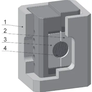
Concluding this section, we come back to the mentioned studies that demonstrated the role of the specifics of polymer mechanics on the deformation mode. The dedicated rig designed and built for that purpose (Fig. 8) makes it possible to deform the material by shear. The body of the rig 1 contains inserts 2 and 3 with half-cylinder channels. A cylindrical sample 4 with a mesh inscribed on its circular end-face is placed in the channel and a vertical load is applied to one of the inserts. The displacement of the inserts with respect to one another leads to shear deformation of the sample in the transverse plane, while its axial elongation is also allowed. The latter circumstance distinguishes the method proposed from other methods of shear testing, which are rigid in prescribing the kinematic constraints on the material flow. Due to additional degrees of freedom available to the material in the former case, the behaviour of the material is governed by its rheological flow. Video recording during a test
documents the distortions of the inscribed coordinate mesh in parallel with the measurement of the load on the inserts. The loading rig can be placed in a high pressure (up to 500 MPa) container, which enables investigation of shear under pressure. In this case the distortions of the mesh are recorded intermittently, rather than continuously.
Figure 9 shows the shear of samples of PA-6 and the aluminium alloy 6061. Evaluation of the mesh pattern according to the method120) yields the components of the strain and rotation tensor. The results indicate that the deformation of the metallic alloy is close to simple shear. By contrast, the PA-6 sample exhibits elongation in the direction inclined to the contact plane between the inserts 2 and 3. Its deformation is close to the pure shear mode.
We would now like to demonstrate that in FEM simulations this effect can be accounted for by considering the strain rate sensitivity of the deformation resistance characteristic of polymers. We use the software package QForm.121)The constitutive law for the polymer is taken in the form
·¼A¾m1_¾m2 ð3Þ
which takes into account the dependence of the flow stress
· on the plastic strain ¾ and the plastic strain rate ¾_. The exponentsm1and m2are considered to be constant.
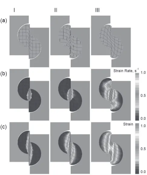
The numerical experiments I, II, III depicted in Fig. 10 are conducted on the basis of the above constitutive equation
Fig. 8 Schematics of a rig for shear deformation materials.
(a) (b) (c) (d)
[image:8.595.347.505.72.231.2] [image:8.595.124.469.620.770.2]using the model parameter values presented in Table 5. As seen from Fig. 10, including the strain rate sensitivity in the simulations does, indeed, lead to a qualitative change of the distorted mesh pattern.
While the numerical experiments I and II, with zero strain rate sensitivity, exhibited deformation behaviour close to simple shear along the interface between the inserts, experiment III showed an elongation of the mesh along a direction inclined to the interface.
These encouraging qualitative results suggest that quantitative predictions of the behaviour of polymers using numerical simulations will be possible, once adequate, physically based constitutive model of the deformation behaviour and microstructure variation of polymers become available. This is regarded as an area of research worth investing manpower and resources.
4. Conclusions
Based on the literature data and the authors’ own results reviewed in this article, the following conclusions can be drawn:
(1) The SPD techniques considered, including high pressure torsion, equal channel angular extrusion, equal
channel multiple angular extrusion, T-shape equal channel extrusion, twist extrusion, and planar twist extrusion, make it possible to accumulate large plastic strain in polymers without changing the shape and dimensions of initial billets. The nature of the changes they induce at the various levels of structural architecture of the polymers is determined by the deformation route and the processing conditions. (2) SPD can cardinally alter the physical and mechanical
properties of polymer materials with various architec-ture and through that impart to them a qualitatively change their property profile. As a rule, the property-modifying effect of SPD is much more pronounced in polymers than in metals.
(3) For uptake of SPD of polymer and polymer composites by industry for efficient commercial use, further studies are required. For materials design and process optimisation, computer simulations using physically based constitutive models will be indispensable.
REFERENCES
1) P.W. Bridgman:Phys. Rev.48(1935) 825847.
2) A.P. Zhilyaev and T.G. Langdon:Prog. Mater. Sci.53(2008) 893 979.
3) V.M. Segal:Mater. Sci. Eng. A197(1995) 157164.
4) R.Z. Valiev and T.G. Langdon:Prog. Mater. Sci.51(2006) 881981.
5) V.A. Beloshenko, V.N. Varyukhin, A.V. Voznyak and Yu.V. Voznyak:
Polym. Eng. Sci.50(2010) 10001006.
6) V. Beloshenko and V. Spuskanyuk: Int. J. Mater. Chem.2(2012) 145 150.
7) V.A. Beloshenko, V.N. Varyukhin, A.V. Voznyak and Yu.V. Voznyak:
Dokl. Phys. Chem.426(2009) 8183.
8) Y. Beygelzimer, R. Kulagin, Y. Estrin, L.S. Toth, H.S. Kim and M.I. Latypov:Adv. Eng. Mater.19(2017) 1600873.
9) Y. Beygelzimer, D. Prilepo, R. Kulagin, V. Grishaev, O. Abramova, V. Varyukhin and M. Kulakov:J. Mater. Process. Technol.211(2011) 522529.
10) R.Z. Valiev, Y. Estrin, Z. Horita, T.G. Langdon, M.J. Zechetbauer and Y.T. Zhu:JOM58(4) (2006) 3339.
11) V.A. Zhorin, Y.V. Kissin, Y.V. Luizo, N.M. Fridman and N.S. Yenikolopyan:Polym. Sci. U.S.S.R.18(1976) 30573061.
12) V.A. Zhorin, A.Y. Malkin and N.S. Yenikolopyan: Polym. Sci. U.S.S.R.21(1979) 896901.
13) V.A. Zhorin, A.V. Maksimychev, A.T. Ponomarenko and N.S. Enikolopyan:Russ. Chem. Bull.28(1979) 20782082.
14) V.A. Zhorin, Y.K. Godovskii and N.S. Yenikolopyan: Polym. Sci. U.S.S.R.24(1982) 10731080.
15) V.A. Zhorin, N.A. Mironov, V.G. Nikol’skii and N.S. Yenikolopyan:
Polym. Sci. U.S.S.R.22(1980) 440447.
16) V.A. Zhorin:Polym. Sci. U.S.S.R.23(1981) 19911999.
17) V.A. Zhorin, V.M. Usichenko, Y.M. Budnitskii, M.S. Akutin and N.S. Yenikolopyan:Polym. Sci. U.S.S.R.24(1982) 21602166.
18) V.A. Zhorin, V.V. Kulakov, N.A. Mironov, V.G. Nikol’skii, A.E. Chebotarevskii and N.S. Yenikolopyan: Polym. Sci. U.S.S.R. 24 (1982) 10811084.
19) A.N. Kryuchkov, V.A. Zhorin, S.S. Lalayan, E.V. Prut, V.G. Nikol’skii, Y.M. Budnitskii, M.S. Akutin and N.S. Yenikolopyan:
Polym. Sci. U.S.S.R.24(1982) 211217.
20) V.A. Zhorin, S.I. Beshenko, Yu.A. Berlin and N.S. Enikolopyan: Polym. Sci. U.S.S.R.24(1982) 23042307.
21) V.A. Zhorin, N.Y. Rapoport, A.N. Kryuchkov, L.S. Shibryayeva and N.S. Yenikolopyan:Polym. Sci. U.S.S.R.25(1983) 679684.
22) V.B. Vol’eva, V.A. Zhorin, A.L. Khristyuk, V.V. Ershov and N.S. Enikolopyan:Russ. Chem. Bull.32(1983) 342345.
23) V.B. Vol’eva, V.A. Zhorin, V.V. Ershov and N.S. Enikolopyan:Russ. Chem. Bull.33(1984) 13251333.
(a)
(b)
[image:9.595.48.291.58.346.2](c)
Fig. 10 Results of FEM simulations of shear deformation of polymer samples with and without strain rate sensitivity.
[image:9.595.48.290.416.481.2]24) L.V. Kompaniets, I.L. Dubnikova, N.A. Erina, E.V. Prut, S.A. Kuptsov and A.A. Zharov: Polym. Sci. Ser. A41(1999) 357363.
25) S.Z. Rogovina, T.A. Akopova, A.N. Zelenetskii, G.A. Vikhoreva, I.N. Gorbacheva and A.A. Zharov: Polym. Sci. Ser. A42(2000) 59. 26) L.V. Kompaniets, I.L. Dubnikova, E.V. Prut, S.A. Kuptsov and A.A.
Zharov: Polym. Sci. Ser. A43(2001) 332336.
27) S.Z. Rogovina, A.B. Solov’eva, N.A. Aksenova and A.A. Zharov: Polym. Sci. Ser. A46(2004) 238241.
28) A.A. Zharov: Polym. Sci. Ser. B46(2004) 268287.
29) V.A. Zhorin and M.R. Kiselev:Int. Polym. Sci. Techn.45(2018) 79 86.
30) Y. Estrin, R. Kulagin and Y. Beygelzimer: Materials Today (2018) https://www.materialstoday.com/surface-science/comment/think-big-manufacture-small/.
31) Y. Ivanisenko, R. Kulagin, V. Fedorov, A. Mazilkin, T. Scherer, B. Baretzky and H. Hahn:Mater. Sci. Eng. A664(2016) 247256.
32) Y. Estrin and A. Vinogradov:Acta Mater.61(2013) 782817.
33) H.-J. Sue and C.K.-Y. Li:J. Mater. Sci. Lett.17(1998) 853856.
34) V. Beloshenko, Y. Beygelzimer and Y. Voznyak: Solid-State Extrusion, 116, in: Encyclopedia of Polymer Science and Technology, 4th Edition, (Carnegie Mellon University, 2015). 35) B. Campbell and G. Edward:Plast. Rubber Compos.28(1999) 467
475.
36) C.K.-Y. Li, Z.-Y. Xia and H.-J. Sue:Polymer41(2000) 62856293.
37) Z.-Y. Xia, H.-J. Sue and T.P. Rieker: Macromolecules 33 (2000) 87468755.
38) Z. Xia, H.-J. Sue, A.J. Hsieh and J.W.-L. Huang:J. Polym. Sci. B39 (2001) 13941403.
39) Z. Xia, H.-J. Sue and A.J. Hsieh: J. Appl. Polym. Sci. 79(2001) 20602066.
40) Z. Xia, T. Hartwig and H.-J. Sue:J. Macromol. Sci. B43(2004) 385 403.
41) T.S. Creasy and Y.S. Kang:J. Thermoplast. Comp. Mater.17(2004) 205227.
42) J.I. Weon, T.S. Creasy, H.-J. Sue and A.J. Hsieh:Polym. Eng. Sci.45 (2005) 314324.
43) J.I. Weon and H.-J. Sue:Polymer46(2005) 63256334.
44) A. Phillips, P. Zhu and G. Edward:Macromolecules39(2006) 5796 5803.
45) J.I. Weon, Z.-Y. Xia and H.-J. Sue:J. Polym. Sci. B43(2005) 3555 3566.
46) J. Qiu, T. Murata, X. Wu, M. Kitagawa and M. Kudo: J. Mater. Process. Technol.212(2012) 15281536.
47) Z.-Y. Xia, H.-J. Sue and T.P. Rieker: Macromolecules 33 (2000) 87468755.
48) Z.-G. Wang, Z.-Y. Xia, Z.-Q. Yu, E.-Q. Chen, H.-J. Sue, C.C. Han and B.S. Hsiao:Macromolecules39(2006) 29302939.
49) J. Ma, G.P. Simon and G.H. Edward:Macromolecules41(2008) 409 420.
50) H. Cui, L. Zhang, J. Gong, Y. Ma and W. Ying:Macromol. Symp.242 (2006) 5559.
51) S. Al-Goussous, X. Wu, Q. Yuan and K. Xia: Mater. Forum31(2007) 3638.
52) Pat. 2012/0178892A1 US, C08F 110/02. Angular extrusion for polymer consolidation/Douglas W. Van Citters.Publ. 12.06.2012. 53) X. Zhang, D. Gao, X. Wu and K. Xia:Eur. Polym. J.44(2008) 780
792.
54) T. Wang, S. Tang and J. Chen:J. Appl. Polym. Sci.122(2011) 2146 2158.
55) X. Zhang, X. Wu, D. Gao and K. Xia:Carbohydr. Polym.87(2012) 24702476.
56) S. Yoshioka and K. Tsukamoto:Jpn. Soc. Mater. Sci.58(2009) 29 34.
57) T.S. Creasy and Y.S. Kang:J. Mater. Process. Technol. 160(2005) 9098.
58) J.I. Weon and H.-J. Sue:Polymer46(2005) 63256334.
59) H. Li, X. Huang, C. Huang and Y. Zhao:J. Appl. Polym. Sci.123 (2012) 22222227.
60) H. Li, C. Huang and X. Huang: J. Appl. Polym. Sci. 131(2014) 39759.
61) F. Bouaksa, C. Ovalle Rodas, F. Zaïri, G. Stoclet, M. Naït-Abdelaziz,
J.M. Gloaguen, T. Tamine and J.M. Lefebvre:Comput. Mater. Sci.85 (2014) 244252.
62) Y.R. Seo and J. Weon:J. Korean Phys. Soc.63(2013) 114119.
63) V.A. Beloshenko, Y.V. Voznyak, I.Yu. Reshidova, M. Naït-Abdelaziz and F. Zairi:J. Polym. Res.20(2013) 322.
64) Y. Bai, X. Zhang and K. Xia: Cellulose (2018)doi:10.1007/ s10570-018-2125-4.
65) X. Wu, L. Pu, Y. Xu, J. Shi, X. Liu, Z. Zhong and S.-N. Luo:RSC Adv.8(2018) 2258322591.
66) S.D. Reinitz, A.J. Engler, E.M. Carlson and D.W. Van Citters:Mater. Sci. Eng. C67(2016) 623628.
67) X. Liu, S.-I. Jung, H.-S. Choi, J.-T. Oh and J.-K. Kim:Korean Chem. Eng. Res.49(2011) 206210.
68) H. Li, Z. Wu, F. Xue, J. Bai and C. Chu:Polym. Eng. Sci.58(2018) 665672.
69) R. Boulahia, J.M. Gloaguen, F. Zaïri, M. Naït-Abdelaziz, R. Seguela, T. Boukharouba and J.M. Lefebvre:Polymer50(2009) 55085517.
70) V.A. Beloshenko, A.V. Voznyak and Yu.V. Voznyak:Polym. Sci. Ser. A51(2009) 916922.
71) V.A. Beloshenko, A.V. Voznyak and Yu.V. Voznyak:High Press. Res. 31(2011) 153157.
72) V.A. Beloshenko, V.N. Varyukhin, A.V. Voznyak and Yu.V. Voznyak:
Polym. Eng. Sci.51(2011) 10921098.
73) V.A. Beloshenko, V.N. Varyukhin, A.V. Voznyak and Yu.V. Voznyak:
J. Appl. Polym. Sci.126(2012) 837844.
74) V.A. Beloshenko, A.V. Voznyak, Yu.V. Voznyak, V.A. Glasunova and T.E. Konstantinova:Polym. Eng. Sci.52(2012) 18151820.
75) V.A. Beloshenko, A.V. Voznyak, Yu.V. Voznyak and S.V. Prokhorenko:Dokl. Phys. Chem.449(2013) 8890.
76) V.A. Beloshenko, A.V. Voznyak, Yu.V. Voznyak and G.V. Dudarenko:
J. Appl. Polym. Sci.127(2013) 13771386.
77) V.A. Beloshenko and Yu.V. Voznyak:Mater. Sci.49(2013) 110116.
78) V.A. Beloshenko, A.V. Voznyak and Yu.V. Voznyak:Polym. Eng. Sci. 54(2014) 531539.
79) V.A. Beloshenko, Yu.V. Voznyak and V.M. Mikhal’chuk:Polym. Sci. Ser. A56(2014) 269274.
80) V.A. Beloshenko, A.V. Voznyak and Yu.V. Voznyak: Dokl. Phys. Chem.457(2014) 117119.
81) V.A. Beloshenko, A.V. Voznyak and Yu.V. Voznyak:J. Appl. Polym. Sci.132(2015) 42180.
82) V.A. Beloshenko, A.V. Voznyak, Yu.V. Voznyak, L.A. Novokshonova, V.G. Grinyov and V.G. Krasheninnikov: Int. J. Polym. Sci.2016(2016) 8564245.
83) V.A. Beloshenko, A.V. Voznyak, Yu.V. Voznyak and A.V. Kupreev:
Dokl. Phys. Chem.466(2016) 2528.
84) V.A. Beloshenko, A.V. Voznyak, Yu. Voznyak, L.A. Novokshonova and V.G. Grinyov:Comp. Sci. Tech.139(2017) 4756.
85) V.A. Beloshenko, Yu. Voznyak, A.V. Voznyak and B. Savchenko:
Compos., Part B112(2017) 2230.
86) Yu.V. Voznyak:Macromol. Res.25(1) (2017) 3844.
87) V.A. Beloshenko, A.V. Voznyak, I. Vozniak and B. Savchenko:
Polym. Eng. Sci.59(2019) 714723.
88) V.A. Beloshenko, Y.E. Beygelzimer, Yu. Voznyak, B.M. Savchenko and V.Y. Dmitrenko:J. Appl. Polym. Sci.135(2018) 45727.
89) O. Prokof’eva, Yu.V. Voznyak and D. Prilepo: Phys. Tech. High Press.23(2013) 116123.
90) A. Vinogradov and Y. Estrin:Prog. Mater. Sci.95(2018) 172242.
91) R. Kulagin, Y. Beygelzimer, Y. Ivanisenko, A. Mazilkin and H. Hahn: Mater. Sci. Eng.194(2017) 012045.
92) B.J. Lee, A.S. Argon, D.M. Parks, S. Ahzit and Z. Bartczak:Polymer 34(1993) 35553575.
93) A.S. Argon:J. Comp. Mater. Design4(1997) 7598.
94) L. Anand and M.E. Gurtin:Int. J. Solids Struct.40(2003) 14651487.
95) S. Nikolov, R.A. Lebensohn and D. Raabe:J. Mech. Phys. Solids54 (2006) 13501375.
96) C. Regrain, L. Laiarinandrasana, S. Toillon and K. Saï:Int. J. Plast.25 (2009) 12531279.
97) J.A.W. van Dommelen, M. Poluektov, A. Sedighiamiri and L.E. Govaert:Mech. Res. Commun.80(2017) 49.
469476.
100) A.M. Laptev, A.V. Perig and O.Yu. Vyal:Mater. Res.17(2014) 359 366.
101) A.V. Perig, A.M. Laptev, N.N. Golodenko, Y.A. Erfort and E.A. Bondarenko:Mater. Sci. Eng. A527(2010) 37693776.
102) A.V. Perig and N.N. Golodenko: Int. J. Adv. Manuf. Technol. 74 (2014) 943962.
103) V.M. Segal, V.I. Reznikov, A.E. Drobyshevskiy and V.I. Kopylov: Russ. Metall.1(1981) 99105.
104) Y. Iwahashi, J. Wang, Z. Horita, M. Nemoto and T.G. Langdon:Scr. Mater.35(1996) 143146.
105) V.M. Segal:Mater. Sci. Eng. A345(2003) 3646.
106) F. Bouaksa, C. Ovalle Rodas, F. Zaïri, G. Stoclet, M. Naït-Abdelaziz, J.M. Gloaguen, T. Tamine and J.M. Lefebvre:Comput. Mater. Sci.85 (2014) 244252.
107) B. Aour, F. Zaïri, J.M. Gloaguen, M. Naït-Abdelaziz and J.M. Lefebvre:Comput. Mater. Sci.37(2006) 491506.
108) F. Zaïri, B. Aour, J.M. Gloaguen, M. Naït-Abdelaziz and J.M. Lefebvre:Comput. Mater. Sci.38(2006) 202216.
109) F. Zaïri, B. Aour, J.M. Gloaguen, M. Naït-Abdelaziz and J.M. Lefebvre:Scr. Mater.56(2007) 105108.
110) B. Aour, F. Zaïri, M. Naït-Abdelaziz, J.M. Gloaguen, O.R. Ahmani and J.M. Lefebvre:Int. J. Mech. Sci.50(2008) 589602.
111) F. Zaïri, B. Aour, J.M. Gloaguen, M. Naït-Abdelaziz and J.M. Lefebvre:Polym. Eng. Sci.48(2008) 10151021.
112) B. Aour, F. Zaïri, M. Boulahia, M. Naït-Abdelaziz, J.M. Gloaguen and J.M. Lefebvre:Comput. Mater. Sci.45(2009) 646652.
113) B. Aour, F. Zaïri, M. Naït-Abdelaziz, J.M. Gloaguen and J.M. Lefebvre:J. Manuf. Sci. Eng.131(2009) 031016.
114) B. Aour, F. Zaïri, M. Naït-Abdelaziz, J.M. Gloaguen and J.M. Lefebvre:Key Eng. Mater.424(2010) 7178.
115) A. Mitsak and B. Aour:J. Braz. Soc. Mech. Sci. Eng. 39(2017) 20552069.
116) A.V. Perig, A.M. Laptev, N.N. Golodenko, Y.A. Erfort and E.A. Bondarenko:Mater. Sci. Eng. A527(2010) 37693776.
117) B. Aour and A. Mitsak:J. Theor. Appl. Mech.54(2016) 263275.
118) A. Draï and B. Aour:Eng. Struct.46(2013) 8793.
119) H.-J. Sue, H. Dilan and C.K.-Y. Li:Polym. Eng. Sci.39(1999) 2505 2515.
120) G.D. Del’: Technological Mechanics, (Mashinostroenie Publishers, Moscow, 1974) (in Russian).