Harmonic. The grain refinement at the surface of the milled powder particles occurs through the recrystallization of the severely-deformed surface layers during sintering, and results in a microduplex structure which gradually transitions to a coarse duplex structure away from the particles surface. Both the recrystallization mechanism and the effect of this refined structure on the sinterability andfinal mechanical properties of the compacts are investigated. [doi:10.2320/matertrans.MH201321]
(Received April 30, 2013; Accepted June 13, 2013; Published July 19, 2013)
Keywords: harmonic structure, duplex stainless steel, microduplex structure, mechanical property, mechanical milling, spark-plasma sintering
1. Introduction
The novel concept of Harmonic structure design13) implies the formation of a high-strength 3-dimensional network of interconnected ultra-fine-grained (UFG) regions; this network, referred to as the “shell”, surrounds and separates softer coarse-grained islands (“cores”) that play an important role in preventing early plastic instability of the material during plastic deformation. The recently-developed design has thus far been successfully applied to single-phase structures such as pure Ti and Ti alloys, Cu and stainless steels. However, the applicability of this design to a two-phase material has not been investigated to date.
Duplex stainless steels, that consist of comparable fractions of ferrite (¡) and austenite (£) phases, are intensely researched for their good strength and superior corrosion resistance. Moreover, the microduplex structure, a refined structure obtained by specific thermo-mechanical processing, has been shown to exhibit superplasticity due to the shape, size and dispersion of the£-phase precipitates.4,5)The current study aims to apply the Harmonic structure design to a SUS 329J1 two-phase stainless steel, and to take advantage of the superplastic behavior of the microduplex structure in order to produce a high-strength duplex stainless steel that retains good plasticity.
2. Experimental Procedures
A SUS 329J1 powder with the chemical composition of 29.8Cr, 4.17Ni, 1.76Mo, 0.9Mn, 0.27C, 0.23Si, 0.03P, 0.02N, 0.01Cu, (in mass%, the balance is Fe) was obtained in a fully-ferritic form with an average particle size of 135 µm using the Plasma-Rotating Electrode Process (PREP). The alloy has a fully-ferritic structure above approximately 1550 K and an austenite phase precipitates from the ferrite
matrix phase to form (ferrite (¡)+austenite (£)) two phases below this temperature. The initial powder structure was a fully-ferritic due to the rapid solidification during the powder fabrication. The powder was milled for 90 ks at ambient temperature under Ar atmosphere in a Fritsch Pulverisette 5 planetary ball mill using SUS 304 L vials and balls. The milling was carried out at 200 rpm with balls-to-powder ratio of 1.8. Subsequently, the milled powder was con-solidated by spark-plasma sintering at 1123 K under a pressure of 50 MPa, wherein the holding time was varied between 600 s and 3.6 ks. The sintered compacts had a disc-shape with 15 mm diameter and approximately 4 mm thickness. Microstructural characteristics of both the milled powders and the sintered compacts were investigated by optical microscopy (OM), scanning electron microscopy (SEM) and electron backscatter diffraction (EBSD) methods. The mechanical properties of the sintered as well as bulk material were evaluated by tensile tests on the sub-sized specimens with gauge of dimensions 3(l)©1(w)©1(t) (all dimensions in mm). The bulk specimen for tensile test was solution treated at 1573 K for 1.8 ks followed by water quench and then annealed at 1123 K for 3.6 ks. Micro-Vickers hardness tests of the compacts were carried out at 245.2 mN for 5 s.
3. Results and Discussion
3.1 Microstructure of powder and the sintered compacts
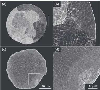
Figures 1(a) and 1(b) show cross-sections of the as-received powder, and Figs. 1(c) and 1(d) show that of the milled powder (milled for 90 ks). Figures 1(b) and 1(d) are enlargement of the rectangular areas indicated in (a) and (c), respectively. The milling parameters were controlled so as to preserve the shape and size of the initial powder particles and to produce a severely deformed layer in the surface region. Meanwhile, as shown in Figs. 1(c) and 1(d), the center of the milled particles retains the dendritic structure of the initial powder. The average Micro-Vickers hardness of the initial
+1Graduate Student, Ritsumeikan University
powder was 332. However, the milled powder indicated the average hardness of 410 in the center and that of 427 in the surface region.
[image:2.595.106.490.68.414.2]Figure 2 indicates change of density of the powders with the sintering time. After a sintering time of 600 s under the conditions described earlier, the relative density of the compact obtained from the milled powder was estimated to be more than 99%, based on micrographic image analysis, in contrast to 96% in the compact obtained from the initial powder. It is obvious that the acceleration of sintering took place in the milled powder.
Figure 3 shows optical micrographs of compacts of the initial powder (without milling) and the milled powder (milled for 90 ks) sintered at 1123 K for 3.6 ks, respectively. As indicated in Fig. 3(a), Widmanstätten£precitates (bright phase) uniformly dispersed in the ¡ matrix, while, in Fig. 3(b), a network structure composed of fine grains has formed. This network, referred to as the “shell”, surrounds and separates softer coarse-grained islands (“core”). An (¡+£) microduplex structure of two phase stainless steel forms by solution treatment at ¡ single phase temperature followed by heavy deformation and annealing at two phase temperature region.6) Thus, the shell structure shown in Fig. 3(b) was the result of severe plastic deformation of the powder surface by mechanical milling. In addition, single phase “Shell and Core” harmonic structure can be easily formed by sintering of milled powders in many metallic materials such as IF steel, SUS316L, SUS304L, pure Cu, pure Ti and Ti6Al4V alloy13).
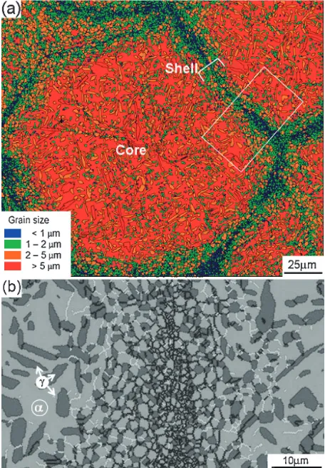
Figure 4 shows (a) a grain size map and (b) a phase map combined with the misorientation map by EBSD. Figure 4(a) was based on EBSD data collected from an area of 260©230 µm with a resolution of 250 nm, in a typical region in the powder sintered for 3.6 ks. The microstructure is very similar to the one of microstructures sintered for 600 s. The color coding indicates the grain size transition from the typical coarse (¡+£) duplex structure in the core, the central regions of particles prior to sintering, to a muchfiner
Fig. 1 Cross-section aspects of the (a), (b) initial, fully-ferritic powder and (c), (d) powder milled for 90 ks. (b), (d): An enlargement of squared areas in (a) and (c), respectively.
[image:2.595.75.264.466.613.2]structure in the shell, formed at the initial particle interfaces. The area marked by a white rectangle is shown in greater detail, with overlaid phase and boundary maps. In Fig. 4(b), dark precipitates are £ phase, and bright and dark lines are low angle boundaries (LABs) and high angle boundaries (HABs), respectively. The analytical misorientation angle of LAB was set to be less than 15 degrees. The £ precipitates are confirmed to have uniform distributions and similar volume fractions in both the core and the shell regions. The precipitates in the shell also appear to be equiaxed. It is noteworthy that a narrow ultra-fine microduplex structure lies in the center of the shell region. Based on the microstructural difference, the narrow microduplex structure and the neighboring microduplex structure are designated as “ mid-shell” and “outer-shell”, respectively. As can be seen in Fig. 4(b), the concentration of LAB (white lines) was observed mainly in the outer-shell region.
Figure 5 indicates length ratio of LAB in the shell region. A shell region with 95 µm©10 µm rectangle area was devided into 5 µm©10 µm small rectangular pieces, and LAB ratio of each piece was calculated using EBSD misorientation map with step size of 250 nm. It was found that ¡-¡ grains have less LABs in the mid-shell region, and the ratio of LAB increases in the areas away from the mid-shell. This implies that (¡+£) two phase micro-structure evolution behavior is different in the mid-shell and the outer-shell.
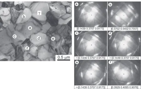
Figure 6 shows a TEM micrograph of the mid-shell and the outer-shell boundary region. Arrows indicate an approx-imate position of the boundary between the mid-shell and the outer-shell region. The average grain size of the mid-shell
and the outer-shell was estimated approximately 570 nm and 1.26 µm, respectively. It was found that the mid-shell has a nanoduplex structure, while the outer-shell has a microduplex structure. The microduplex structure observed in the outer-shell is very common in the severely deformed and annealed two phase stainless steel.6)Annealing of a severely deformed ¡ single phase matrix at an (¡+£) two phase temperature region results in an (¡+£) microduplex structure, which consists of ¡ subgrains and £ precipitates. Such a micro-structural evolution occurs due to the precipitation of£phase
Fig. 3 Optical micrographs of compacts sintered at 1123 K for 3.6 ks. (a) an initial powder (without milling) and (b) a milled powder (milled for 90 ks).
Fig. 4 A grain size map (a) and a phase map (b), which is combined with the boundary map obtained from EBSD data. Bright and dark lines are low angle boundaries (LABs) and high angle boundaries (HABs), respectively.
[image:3.595.313.541.71.399.2] [image:3.595.319.533.473.628.2]prior to the recrystallization of the ¡ phase. The £ phase precipitates at¡sub-boundaries and pins the grain growth of the¡subgrain structure.
Figure 7 shows a TEM micrograph taken from a mid-shell region which is rather close to the outer shell. Kikuchi patterns and the incident beam directions are also indicated in the figure. The grains marked as (a)(f ) are ¡ phase. The Kikuchi patterns of (a), (c), (d) and (e) grains are quite similar, that is, they have similar crystallographic orientation. In addition, the deviation angle between incident beam directions of (a) and (f ) was calculated as 3.7 deg., which indicates that the grain boundaries between these grains, (a), (c), (d), (e) and (f ), are LABs. However, high angle boundary between (a) and (b), with 18.7 deg. of misorientation, was also observed. Existence of such a high angle boundary in
the mid-shell implies that extremely severe plastic deforma-tion in the very surface of the powder caused local crystal rotaion to form nano scale grains with HABs prior to £ precipitation.
The microstructure detail and the grain boundary misor-ientation analysis shown in above figures emphasize that the process of formation of two kinds of shells, i.e., mid-shell and outer-shell, strongly depends on the precipitation behav-ior of the second phase and recovery and recrystallization of the matrix phase. This is the reason why single shell and core harmonic structure was observed in single phase materials.2,3) The significantly-improved sinterability observed after milling, as indicated in Fig. 2, can be explained by super-plastic deformation of an (¡+£) microduplex structure of shell region in the milled powder. A cold-rolled fully-ferritic
Fig. 6 TEM micrograph of the mid-shell and the outer-shell boundary region. Arrows indicate an approximate position of the boundary.
[image:4.595.85.515.72.248.2] [image:4.595.74.525.283.568.2]duplex steel followed by annealing in the two-phase field produces the typical microduplex structure, in which the ¡ matrix is in a recovered condition, as subgrains with fairly low misorientations.5,6)Tsuzakiet al.5)showed that the angle of misorientation of ¡ subgrain boundaries shows gradual increase with straining, by dynamic recovery, through the continuous migration of the accumulated dislocations to the subgrain boundaries; when the misorientations become high enough, superplastic grain sliding starts to occur.
3.2 Mechanical properties
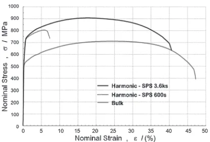
The nominal tensile stressstrain curves of conventional bulk duplex steel and harmonic structure one are plotted in Fig. 8. The harmonic structure compact shows a yield strength ³40% higher than the bulk, homogeneous duplex structure, while the tensile strength is improved by>25%. In spite of this significant strengthening, the harmonic structure compact still exhibits a remarkable uniform elongation of
³17%.
The dotted line in Fig. 8 indicates that the sintering time has a major effect on the plasticity of the harmonic specimens. This is attributed only marginally to the densification of the compacts during sintering, since even a sintering time of 600 s is sufficient to lead to almost 99% relative density. Rather, it is expected that the strength of the bonding at the particle interfaces increases with the increase of sintering time. The effect of the longer sintering time is
the microstructure led to improved strength without signifi -cant loss in plasticity, while the thermal stability of the microduplex structure allowed for longer sintering times without compromising the gains in strength obtained through grain refinement.
Acknowledgments
This research was supported by the Japan Science and Technology Agency (JST) under Collaborative Research Based on Industrial Demand “Heterogeneous Structure Control: Towards Innovative Development of Metallic Structural Materials”, and by the Grant-in-Aid for Scientific Research on Innovative Area,“Bulk Nanostructured Metals”, through MEXT, Japan (contract No. 22102004). These supports are gratefully appreciated.
REFERENCES
1) H. Fujiwara, R. Akada, A. Noro, Y. Yoshita and K. Ameyama:Mater. Trans.49(2008) 9096.
2) H. Fujiwara, S. Takarae and K. Ameyama: Proc. 2nd Int. Symp. on Steel Science 2009 (ISSS2009), ISIJ, (2010) pp. 269272.
3) T. Sekiguchi, K. Ono, H. Fujiwara and K. Ameyama:Mater. Trans.51
(2010) 3945.
4) Y. Zhang, F. Dabkowski and N. J. Grant:Mater. Sci. Eng. 65(1984) 265270.
5) K. Tsuzaki, H. Matsuyama, M. Nagao and T. Maki: Mater. Trans. JIM31
(1990) 983994.
[image:5.595.66.273.67.207.2]