Effect of ECAE on Microstructures and Mechanical Properties
of Solution Heat Treated Mg
5(mass
%
) Sn Alloy
Hao-Jan Tsai
1, Chin-Guo Kuo
2, Chuen-Guang Chao
1,+and Tzeng-Feng Liu
11Department of Materials Science and Engineering, National Chiao Tung University, Hsinchu 300, Taiwan 2Department of Industrial Education, National Taiwan Normal University, Taipei 162, Taiwan
The microstructures and mechanical properties of the Mg5(mass%) Sn alloy subjected to a solution heat treatment (SHT) were investigated by using equal channel angular extrusion (ECAE). The average grain size was significantly refined from 147 µm (as-cast) to 16 µm by ECAE four passes. Further, thefine Mg2Sn particles were uniformly distributed in the matrix by dynamic precipitation after ECAE four
passes. The yield strength (YS), ultimate tensile strength (UTS) and elongations also showed notable improvements at room temperature and high temperatures (100 and 200°C) on account of the ECAE process. Further, the tensile strength and elongations were better than those of the ECAE without SHT alloy. Those results show that SHT is a useful way to enhance the effect of ECAE on the mechanical properties of Mg5(mass%) Sn alloy. [doi:10.2320/matertrans.M2013088]
(Received March 6, 2013; Accepted May 27, 2013; Published July 12, 2013)
Keywords: Mg5(mass%) Sn alloy, solution heat treatment (SHT), equal channel angular extrusion (ECAE)
1. Introduction
Magnesium alloys are the lightest metals, which have the best specific rigidity among structural metals. They also have excellent heat dissipation and vibration resistance, which could easily be seen from that used in 3C products and automobile parts.1) The most commercially employed
magnesium alloys are the MgAl binary systems. The ¢ -phase (Mg17Al12) is the main phase to increase the strength
of AZ series magnesium alloys (AZ31, AZ61 and AZ91) at room temperature; however, the AZ series alloys also demonstrat a lower strength at high temperatures. Because the ¢-phase is clearly dissolved in the matrix at high temperature (120°C), increasing the high temperature proper-ties is the most important issue.
Early reports studied the rare earth (RE) addition to magnesium alloys in order to improve the high temperature properties.24) However, RE was an expensive element. In contrast, tin was an inexpensive element and easily obtained. Recently, scholars studied the MgSn based alloy system.514) The MgSn phase diagram showed that the melting point of the Mg2Sn phase (770°C) within the matrix
of MgSn alloys was much higher than that of the Mg17Al12
phase (462°C) in MgAl alloys.14) This fact could signifi
-cantly improve the high temperature properties.
Sasaki et al. and Wei et al. studied the MgSnZn and Mg5(mass%) Sn alloys, respectively, to improve the creep behavior by using aging hardening.8,9) In particular, the
compressive creep resistance of aging treated Mg5(mass%) Sn alloy was much better than that of the as-cast alloy with temperatures from 150 to 200°C at the applied stresses of 25 to 35 MPa.
Beside the aging treatment, some scholars focused on thermo-mechanical treatments to improve the mechanical properties of the MgSn based alloys at high temperatures by obtaining grain refinement as the main strengthening treat-ment.1013)Sasakiet al.used the extrusion process to produce
a fine grain structure at 250°C; thus, an ultimate tensile strength (UTS) of 354 MPa for the MgSnZnAl alloy was attained at room temperature.11)Parket al.studied the Mg 8Sn1Al1Zn alloy.12) The authors used the solution heat treatment (SHT) and indirect extrusion in a two-step process to produce ultra-fine grains (<10 µm). However, they focused on the superplastic properties of the alloy and did not investigate the high temperature strength of the alloy in detail. From the above references, it follows that the aging treatment and thermo-mechanical treatments were powerful ways to increase the high temperature mechanical properties of MgSn alloys.
In our previous study, we investigated the microstructures and mechanical properties of the Mg2,5,8 (mass%) Sn alloys at high temperatures after an ECAE process without SHT.13)The results showed that the Mg5(mass%) Sn alloy had the best mechanical properties at room temperature and high temperatures (100 and 200°C), as well as the mechanical properties clearly improved after ECAE four passes. The tin solubility in the ¡-Mg was demonstrated from the MgSn binary phase diagram; the amount of tin solubility sharply dropped when the eutectic transformation temperature decreased from 561°C (14.85 mass%) to 200°C (0.45 mass%).14) It provided a basis for improving the
mechanical properties of Mg5(mass%) Sn alloy via the SHT or aging treatment.
In the present study, we aim to produce grain refinement and make the distribution of Mg2Sn particles more uniformly
by using the SHT+ECAE two-step process. Furthermore, we attempt to increase the high temperature tensile strength and elongations of the Mg5(mass%) Sn alloy.
2. Experiment Procedure
An MgSn alloy with added tin levels of 5 mass% was prepared. Pure magnesium (99.95 mass%) and pure tin (99.98 mass%) were melted in a crucible under the protection of SF6 flux at 800°C. The melted mixture was stirred to
ensure homogeneity. This was held at 720°C for about 30 min +Corresponding author, E-mail: cgchao@mail.nctu.edu.tw
and finally casted into a steel mould that was preheated to 250°C. The cavity dimensions of the mould were 300© 70©60 mm3. The as-cast ingots were given solution heat
treatment at 480°C for 22 h. The ECAE was conducted with a die having a 120 degree angled channel using the Bc processing route, in which the specimen was removed from the die and then rotated 90 degree in the same direction between each pass. The dimension of specimens was 15© 15©70 mm3.The specimens were then extruded through four passes at afixed temperature of 200°C with an extrusion rate about 2 mm/min. The ECAE temperature was controlled and maintained by thermocouple and digital temperature controller. If the temperature changing was detected by thermocouple, the digital temperature controller could feed-back and adjust the ECAE temperature immediately.
The metallographic specimens were sliced at the same place in each as-cast, as-SHT and ECAE samples. Those specimens were polished and etched with a solution of 5 vol% nitric acid+ethyl alcohol. The microstructures of the Mg5(mass%) Sn alloy was observed by an optical microscope (OM) and a scanning electron microscope (SEM). The tensile specimens were cut into slices having gauge length of 6 mm via the wire-electrode cutting process. The tensile tests were conducted at room temperature and at high temperatures (100 and 200°C) on a tensile testing machine (Instron8500) with a constant strain rate of 1© 10¹3s¹1. The tensile direction (TD) was parallel to the extrusion direction (ED).
3. Results and Discussion
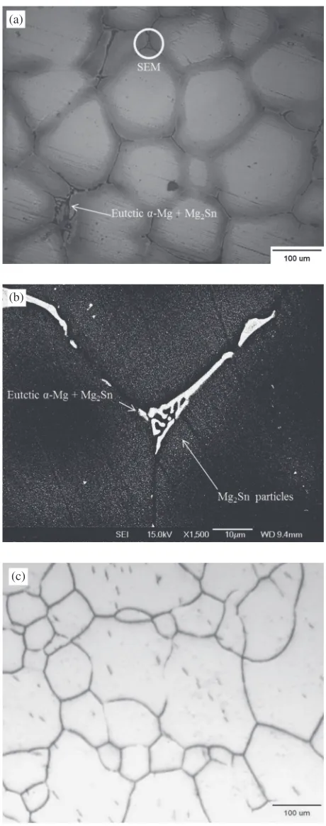
3.1 Microstructures of as-cast and states with SHT Continuous eutectic ¡-Mg+Mg2Sn layered precipitates
could be found at the grain boundary of the as-cast Mg 5(mass%) Sn alloy as shown in Fig. 1(a). However, Fig. 1(a) also showed the difference of brightness near grain boundary. Figure 2(b) could explain this phenomenon. The SEM image demonstrated that a large number of fine Mg2Sn particles
distributed near the grain boundary; suggesting those Mg2Sn
particles which distributed near grain boundary caused the brightness difference. After the SHT at 480°C for 22 h, the microstructure of the Mg5(mass%) Sn alloy significantly changed as shown in Fig. 1(c). The grain boundary was clean in the optical micrograph (OM) of the Mg5(mass%) Sn alloy. It means that the continuous eutectic ¡-Mg+ Mg2Sn precipitates were dissolved in the matrix after water
quenching.
3.2 Microstructures after ECAE process state
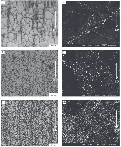
Figures 2(a)2(c) showed the OM images of the Mg 5(mass%) Sn alloy after SHT+ECAE one, two and four passes. The microstructures distribution were homogeneous; the average grain size decreased with increasing ECAE passes from 147 µm (as-cast) to 16 µm (SHT+ECAE four passes).
Figures 2(d)2(f ) showed the SEM images of the Mg 5(mass%) Sn alloy after SHT+ECAE one, two and four passes. Figure 2(d) showed that the fine and discontinuous Mg2Sn particles were precipitated through the dynamic
precipitation during ECAE one pass. Further, thefine Mg2Sn
particles which distributed more uniformly were observed after ECAE two and four passes, as shown in Figs. 2(e) and 2(f ).
Table 1 showed the average grain size of the Mg 5(mass%) Sn alloy with or none SHT after ECAE one, two and four passes. It was clear that the average grain size of the Mg5(mass%) Sn alloy decreased with increasing ECAE
(a)
(b)
(c)
Fig. 1 OM and SEM images of Mg5(mass%) Sn alloy (a) OM as-cast, (b) SEM as-cast and (c) OM as-SHT at 480°C for 22 h.
[image:2.595.312.542.67.649.2]passes; further, the average grain size of Mg5(mass%) Sn alloy with SHT was smaller than that of Mg5(mass%) Sn alloy none SHT. There were two reasons for the decreasing in the average grain size.
First of all, the thermal energy and shear strain were helpful for the dynamic recrystallization (DRX); therefore, the DRX leaded to the production of fine grains. Secondly, (a)
(b)
(c)
(d)
(e)
(f)
[image:3.595.62.537.70.647.2]Fig. 2 Microstructures of Mg5(mass%) Sn alloy after ECAE process (a)N=1 after SHT, (b)N=2 after SHT, (c)N=4 after SHT, (d)N=1 after SHT, (e)N=2 after SHT and (f )N=4 after SHT.
Table 1 Average grain size of Mg5(mass%) Sn alloy.
As-cast SHT+ECAE ECAE none SHT
147.0 µm
N=1 48.4 µm 87.5 µm
N=2 20.3 µm 69.7 µm
[image:3.595.45.290.731.786.2]the as-SHT Mg5(mass%) Sn alloy could dynamicly precipitate a large number of Mg2Sn particles in the grain
boundaries during the ECAE process at high temperature (200°C); further, those particles could retard grain boundary migration. Similarly, Park et al. reported that the thermally stable uniform precipitates at the grain boundaries inhibited grain growth during high temperature deformation.17)
3.3 Tensile properties
Table 2 showed the tensile test results of the Mg 5(mass%) Sn alloy including as-cast, ECAE 4 passes none SHT, as-SHT and ECAE four passes after SHT. All the YS and UTS values increased after ECAE four passes at room temperature and high temperatures (100 and 200°C). The UTS of the Mg5(mass%) Sn alloy after SHT+ECAE four passes significantly increased from 126 to 360 MPa at room temperature. Further, the UTS increased from 103 to 281 MPa at 100°C, as well as increased from 67 to 209 MPa at 200°C. In particular, the YS and UTS values after SHT+ECAE four passes were larger than those of Mg 5(mass%) Sn alloy ECAE four passes none SHT. For example, the UTS of the Mg5(mass%) Sn alloy after SHT+ECAE four passes increased from 67 MPa (as-cast) to 209 MPa at 200°C, but the UTS increased from 67 MPa (as-cast) to 179 MPa at 200°C after ECAE four passes none SHT. Additionally, the YS and UTS of as-SHT were better than that of as-cast, but much poorer than that of SHT+ ECAE four passes. Although the strength of as-SHT Mg 5(mass%) Sn alloy slightly increased by solid solution strengthening, the gains still maintained coarsening after SHT.
Moreover, the elongations of the Mg5(mass%) Sn alloy including as-cast, ECAE 4 passes none SHT, as-SHT and ECAE four passes after SHT were also shown in Table 2. All the elongations of the Mg5(mass%) Sn alloy after SHT+ECAE four passes, and after ECAE four passes none SHT displayed a similar trend. However, all the elongations of the Mg5(mass%) Sn alloy after SHT+ECAE four
passes were larger than those of the alloy after ECAE four passes none SHT. The elongation of the Mg5(mass%) Sn alloy increased slightly from 7.9 to 11.3% at room temper-ature after SHT+ECAE four passes. Further, the elongation increased from 9.7 to 16.8% at 100°C, and the elongation increased significantly from 10.6 to 22.1% at 200°C after SHT+ECAE four passes. On the other hand, all the elongations of the as-SHT Mg5(mass%) Sn alloy were lower than that of ECAE four passes none SHT, and much lower than that of SHT+ECAE four passes.
From the above, a single SHT process could increase in limit the YS and UTS at room and high temperatures (100 and 200°C), but it was not enough to effectively promote the YS, UTS and elongations at the same time. By contrast, the SHT+ECAE two-step process were very helpful to enhance the strength and elongations of Mg5(mass%) Sn alloy at room and high temperatures (100 and 200°C) because the ECAE process still played a key role to obviously increase the strength and elongations by grain refining and precipitates uniformly distribution.
3.4 Fracture surface
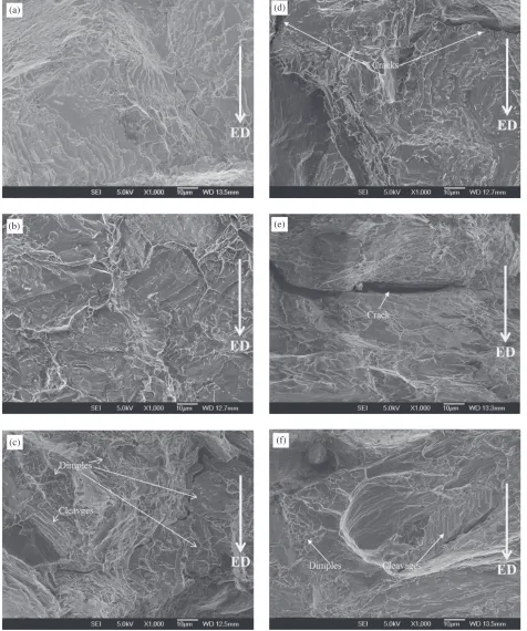
It was well known that a magnesium alloy failed in a brittle mode through cleavage or quasi-cleavage with an HCP structure at room temperature.18)Figures 3(a)3(c) were the fracture surfaces of Mg5(mass%) Sn alloy samples after SHT+ECAE four passes. The tensile tests were conducted with a constant strain rate of 1©10¹3s¹1. Figure 3(a) showed that the fractures were due to the cleavage at room temperature and that several cleavages were present. Figure 3(b) showed the result at 100°C, which was similar to that at room temperature; the cleavage was the major fracture mode. Figure 3(c) showed that the specimen broke at 200°C. The result showed that the fracture surface consisted of dimples and cleavages. This means that the fracture mode of the Mg5(mass%) Sn alloy gradually transformed from the brittle to the ductile through thermal activation. We further compared the fracture surface of as-cast, as-SHT and ECAE four passes none SHT conditions. Figures 3(d) and 3(e) showed that the fracture surface of as-cast and as-SHT broken at high temperature 200°C. The major fracture mode was cleavage and the large cracks were observed in the Figs. 3(d) and 3(e). Furthermore, we compared the fracture surface of Mg5(mass%) Sn alloy after ECAE four passes none SHT in our previous report as shown in Fig. 3(f );13)the fracture surface combined by a lot
of cleavages and a few dimples. This result demonstrated that the Mg5(mass%) Sn alloy after ECAE four passes none SHT had starting transformed from the brittle to the ductile at high temperature 200°C; however, the distribution area of dimples was less than that of SHT+ECAE four passes. This phenomenon indicated that the SHT+ECAE two-step process could significantly enhance ductile of the Mg 5(mass%) Sn alloy.
4. Conclusions
(1) The continuous eutectic ¡-Mg+Mg2Sn precipitates
[image:4.595.48.291.83.292.2]were observed in the as-cast Mg5(mass%) Sn alloy. The grain boundary was clean after SHT.
Table 2 Tensile properties of Mg5(mass%) Sn alloy.
Samples YS (MPa) UTS (MPa) Elongations (%)
as-cast*
R.T 104 126 7.9
100°C 74 103 9.7
200°C 40 67 10.6
N=4 none SHT*
R.T 270 327 9.5
100°C 176 248 14.5
200°C 108 179 18.9
as-SHT
R.T 142 175 4.3
100°C 106 134 6.2
200°C 76 99 7.1
N=4 after SHT
R.T 302 360 11.3
100°C 232 281 16.8
200°C 173 209 22.1
Strain rate=1©10¹3s¹1.*: In our previous report.13)
(2) The ECAE process was helpful for grain refining; the average grain size decreased with increasing ECAE passes from 147 µm (as-cast) to 16 µm (SHT+ECAE four passes).
(3) The fine and uniform Mg2Sn particles of the as-SHT
Mg5(mass%) Sn alloy were produced by dynamic precipitation during ECAE process.
(4) The YS and UTS of the Mg5(mass%) Sn alloy increased after SHT+ECAE four passes at room temperature and high temperatures (100 and 200°C). (5) The fracture surface of the Mg5(mass%) Sn alloy after
SHT+ECAE four passes was due to cleavage at room temperature and 100°C, and the fracture surface consisted of dimples and cleavages at 200°C.
(a)
(b)
(c)
(d)
(e)
(f)
Fig. 3 Fracture surface after tensile test with a constant strain rate 1©10¹3s¹1(a)N=4 after SHT broken atRT, (b)N=4 after SHT
[image:5.595.62.538.74.644.2]Acknowledgements
The authors were pleased to acknowledge the financial support of this research by the National Science Council, Republic of China under Grant NSC 99-2221-E-009-036-MY3.
REFERENCES
1) Y. Kojima:Mater. Trans.42(2001) 11541159.
2) J. Gröbner and R. Schmid-Fetzer:J. Alloy. Compd.320(2001) 296 301.
3) Y. Wang, S. Guan, X. Zeng and W. Ding:Mater. Sci. Eng. A 416 (2006) 109118.
4) W. Blum, P. Zhang, B. Watzinger, B. v. Grossmann and H. G. Haldenwanger:Mater. Sci. Eng. A319321(2001) 735740.
5) M. Bamberger:J. Mater. Sci.41(2006) 28212829.
6) D. H. Kang, S. S. Park, Y. S. Oh and N. J. Kim:Mater. Sci. Eng. A 449451(2007) 318321.
7) C. L. Mendis, C. J. Bettles, M. A. Gibson and C. R. Hutchinson:Mater.
Sci. Eng. A435436(2006) 163171.
8) T. T. Sasaki:Scr. Mater.61(2009) 8083.
9) S. Wei, Y. Chen, Y. Tang, H. Liub, S. Xiao, G. Niu, X. Zhang and Y. Zhao:Mater. Sci. Eng. A492(2008) 2023.
10) Y. V. R. K. Prasad, K. P. Rao, N. Hort and K. U. Kainer:Mater. Lett.62 (2008) 42074209.
11) T. T. Sasaki, K. Yamamoto, T. Honma, S. Kamado and K. Hono:Scr. Mater.59(2008) 11111114.
12) S. S. Park and B. S. You:Scr. Mater.65(2011) 202205.
13) H.-J. Tsai, C.-G. Kuo, C.-G. Chao and T.-F. Liu: Adv. Sci. Lett. 8 (2012) 599604.
14) A. A. Nayeb-Hashemi and J. B. Clark:Bull. Alloy Phase Diagrams5 (1984) 466476.
15) A. Galiyev, R. Kaibyshev and G. Gottstein:Acta Mater. 49(2001) 1199.
16) B. Somjeet, S. D. Satyaveer and S. Satyam:Microstructure and Texture in Steels and Other Materials, (Springer-Verlag, London, 2009) pp. 465473.
17) S. S. Park, G. T. Bae, D. H. Kang, B. S. You and N. J. Kim:Scr. Mater. 61(2009) 223226.
18) Y. Lü, Q. Wang, X. Zeng, W. Ding, C. Zhai and Y. Zhu:Mater. Sci. Eng. A278(2000) 6676.