Abstract— This work presents the implementation of a
wireless network based on Bluetooth Low Energy (BLE) which enables the integration of multiple sensor nodes into a smartphone-based system in order to monitor the posture of cyclists. The developed posture monitoring system obtains the orientation in space of each body segment in which the sensor nodes are placed and calculates the trunk angle, the knee angle and the angle of inclination of the road. Raw sensor data are collected periodically from accelerometers, magnetometers and gyroscopes and sent via BLE to an Android smartphone, which plays the role of central station and performs the data processing concerning the posture calculation. We describe the development of the hardware and software of the sensor nodes, which are based on the CC2540 BLE system-on-chip, as well as the development of the Android application, and provide experimental results concerning the measurement of the posture of a cyclist in order to validate the proposed system.
Index Terms—Posture monitoring, cycling, mobile sensing,
Bluetooth Low Energy, wireless body area networks.
I. INTRODUCTION
Body posture monitoring is an emerging area of study and development, with applications in areas such as sports, healthcare and entertainment. Posture monitoring systems based on wireless body area networks (WBANs) [1] present several advantages compared to conventional systems based on cameras, because, unlike the latter, the former can be used in uncontrolled environments, under any lighting conditions and without line of sight to the receptor.
WBANs require small-sized wireless sensors that can be conveniently placed in the user’s body, as well as low power consumption hardware and energy efficient protocols, in order to provide adequate battery lifetime [2]. In a WBAN usually sensors sent the collected data to a central station (e.g., a personal computer) with capacity to process and store the data. With the technological advancement, smaller personal devices, such as smartphones, also started to become suitable for these tasks, with the advantage of greater portability.
The posture of an athlete during the cycling activity can dramatically influence his performance. Several studies in this area were made, either with elite athletes or amateur cyclists. The aero position, where the cyclist adopts a lowered position with the trunk almost horizontal and the
This work has been supported by FCT (Fundação para a Ciência e Tecnologia) in the scope of the project: PEst-OE/EEA/UI04436/2015.
António F. Maio is with Centro Algoritmi, University of Minho, Campus of Azurém, Guimarães, 4800-058, Portugal (e-mail: [email protected]).
José A. Afonso is with MEMS-UMinho, University of Minho, Campus of Azurém, Guimarães, 4800-058, Portugal (phone: 351-253510190; fax: 351-253510189; e-mail: [email protected]).
arms extended forward with elbows tucked in, has the advantage of reducing the drag imposed by wind resistance. However, in [3], the authors conclude that the upright position allows higher VO2, ventilation, heart rate, and
workload for untrained cyclists performing with maximal effort. Moreover, the upright position makes the cycling exercise less costly during steady state. In [4], the authors conclude that the posture has a very large effect on the performance of active cyclists during constant-load exercises.
Besides the trunk posture, the performance of cyclists can be affected if the angle of the knee is not the most correct. In [5], anaerobic tests were performed with trained and untrained cyclists. Results show that the seat should be adjusted to allow the leg to be flexed by 25-35 degrees for untrained cyclists, in order to contribute to the prevention of injuries and increase the performance.
Mobile sensing is an attractive emerging area of research and development [6], [7] that uses sensor data collected by users’ smartphones to extract relevant information. Some of these research works are applied to cycling, monitoring sensor data from the bicycle, the user’s body or the environment [8], [9], [10].
BikeNet [8] is a project that performs the mapping of user experience based on various sensors adapted to a conventional bicycle using a network of wireless sensors based on the IEEE 802.15.4 standard. In order to provide the interface between the sensor network and a smartphone, this system uses an IEEE 802.15.4/Bluetooth gateway. Data collection focuses on parameters such as noise and carbon dioxide levels, speed, geographical location and user’s stress level. The cyclist’s posture is not monitored.
The Copenhagen Wheel project [9] developed a wheel that can be adapted in a conventional bicycle in order to turn it into an electric bike. An iPhone smartphone communicates with the central part of the wheel (hub) using Bluetooth, providing geographical location services and allowing the user to manually lock/unlock the bike, change the gear and adjust the level of actuation of the electric motor. This system does not collect any physiological data from the cyclist.
This paper presents a system that allows the real-time monitoring of the posture of cyclists through the use of sensor modules placed on the body of the athlete, which send the collected data to an Android smartphone. These modules were developed by us and integrate 3-axis accelerometers, magnetometers and gyroscopes.
The wireless communication between the sensor modules and the smartphone is based on Bluetooth Low Energy (BLE) [11], which is a wireless technology optimized for ultra-low power consumption, designed to be used on
Wireless Cycling Posture Monitoring Based on
Smartphones and Bluetooth Low Energy
devices that have to operate for long periods without having to replace or recharge their batteries. BLE is a new technology that is currently only available on some recent smartphones. However, similarly to previous Bluetooth versions, the trend is for BLE to be integrated on most smartphones in the future. In contrast, IEEE 802.15.4/ZigBee [12], [13], which is an alternative low power wireless technology, generally lacks smartphone support.
This paper is organized as follows: The next section provides a description of all the components of the developed system, including the hardware of the sensor nodes, the code implemented in the nodes and the smartphone application. Section III describes the process for calculating the relevant posture angles. In Section IV, experimental results are presented and discussed. Finally, Section V presents the conclusions.
II. DEVELOPED SYSTEM A. System Overview
[image:2.595.51.286.368.471.2]The cycling posture monitoring system presented in this paper is composed of two main physical components: a smartphone (central station) and multiple wireless sensor nodes on the body of the cyclist, which communicate using BLE, as shown in Fig. 1.
Fig. 1. Architecture of the developed cycling posture monitoring system.
Each sensor node has the task of collecting raw posture data from the body segment where it is placed. The sensor node is composed by two boards: sensor module and wireless module. Each sensor module integrates three sensors: accelerometer, magnetometer and gyroscope, which generate data on each of the three axes: x, y, z. The accelerometer allows detecting the inclination angle between the accelerometer position and the gravity field, the magnetometer provides the angular difference between its position and the magnetic field of the Earth, and the gyroscope compensates errors in the calculation through the detection of rotational movements.
In order to monitor the posture of cyclists, three sensor nodes are placed in the user’s body: one on the chest, in order to measure the inclination of the trunk relative to the horizontal plane; one on the upper leg and one in the lower leg, to obtain the knee angle. In order to calculate the trunk angle (relative to the bicycle), it is necessary to measure the inclination of the bicycle. For this purpose, we chose to use the sensors integrated on the smartphone, which is placed on the bicycle handlebar, taking advantage of the available equipment and thus avoiding the use of another sensor node. The raw data from the sensor modules are sent via BLE to the developed application on a BLE compatible (Bluetooth
Smart Ready) smartphone. Besides performing the basic functions of a Bluetooth connection, the application is capable of calibrating the sensors and calculating the posture angles (pitch, roll and yaw) for each body segment based on the raw data. Based on this information, the application provides the trunk and knee angles of the cyclist. This posture information can be visualized on the application, stored on the smartphone or sent to a remote computer in real-time using Wi-Fi or a mobile data connection.
B. Sensor Node Hardware
The wireless module of the sensor node, shown in Fig. 2 (a), is a Texas Instruments CC2540EM module, which contains a CC2540 SoC (System-on-Chip) [14], an external antenna, two 20-pin connectors that provide access to the pins of the CC2540, and auxiliary components. The CC2540 integrates in the same chip an 8051-based microcontroller with 8 kB RAM and 128 kB of flash memory and a BLE transceiver, which operates in the 2.4 GHz frequency band with a data rate of 1 Mbps. The current sensor node prototype is relatively large due to the size of the external antenna. However, the size of the sensor node can be easily reduced in the future with the use of a wireless module with integrated antenna, such as the Panasonic PAN1720. Since this module is also based on the CC2540 SoC, the same embedded code developed for this prototype could be used without the need of changes.
Fig. 2. Sensor node hardware: (a) wireless module; (b) sensor module top view; (c) sensor module bottom view with the battery.
[image:2.595.312.543.378.559.2]Data acquisition from the sensors to the CC2540 was performed using the SPI (Serial Peripheral Interface) interface of the MPU-6000 chip.
C. Embedded Code
The code developed for the sensor nodes was based on the BLE protocol stack provided by Texas Instruments, version BLE-CC2540-1.3.2. In order to provide adequate communication between two BLE stations in the context of this system, we created a service to send periodic notifications from peripheral stations to the central station, i.e., from slaves to the master. This service is implemented in the peripheral station, which takes the role of GATT (Generic Attribute Profile) server, whereas the central station acts as GATT client.
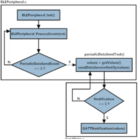
The service created contains only one characteristic, whose value is a 20-byte data frame, and a descriptor (CCC - Client Characteristic Configuration) that activates the mode of periodic notification sending (0x0001). We used notifications instead of the indications because the former does not require further exchange of packets between the master and the slave after the data transmission for the acknowledgement, so the overhead is lower, making the transmission process more efficient. Fig. 3 presents the flowchart of the data transmission process from the peripheral station to the central station.
Fig. 3. Flowchart of the data transmission at the peripheral station.
This process stats at the BLEPeripheral_Init bloc, which is responsible for parameter initialization at the GAP layer with respect, for example, to the role of the device (in this case peripheral), definition of the advertising interval and initialization of the attributes of the GATT layer, more specifically the services implemented. In the next phase, BLEPeripheral_ProcessEvent processes all events that are triggered. In the case of the firmware implemented, whenever an event concerning the periodic data transmission is detected the periodicDataSendTask block is called. This block is responsible to collect the values of the sensors, place them in the data frame payload and call the service created, SendDataServiceNotify. After verifying if
notifications are enabled, this service calls the GATT_Notification function to send the information to the central station.
Data acquisition from the sensor module using SPI can be made using one of three different methods: polling of status bits, interrupt or DMA [15]. Initially, the idea was to use the DMA controller of the BLE stack for data acquisition, but this controller defines a type of packet that does not match the format accepted by the MPU-6000. Therefore, we implemented a function, based on the method of polling of status bits, to read/write the data through SPI without resorting to the BLE stack.
[image:3.595.53.285.370.604.2]After the acquisition of raw data from the sensors, the program constructs the payload of the data frame to be sent to the central station, which is shown in Fig. 4. Each sensor is sampled at 16 bits, which means that 2 bytes are required to represent the x, y and z values from each sensor, resulting in 18 bytes. Each frame includes also a sequence number (SN) and a sensor identifier (SID) to allow the smartphone application to properly identify the origin of the data from the different sensor nodes. Therefore, the length of the payload is 20 bytes, which corresponds exactly to the maximum allowed BLE payload, at application level, for transmission of notifications.
Fig. 4. Data frame payload of the BLE interface.
The sampling rate of the sensors modules was set to 30 Hz, which corresponds to a frame rate of 30 fps, a value typically used by motion capture applications [16]. The BLE connection interval parameter was set to 100 ms and the slave latency was set to zero, which means that each sensor generates three samples per 100 ms. Since it is not possible to send this amount of data in a single notification, each peripheral station has to send three notifications (data frames) per connection event.
D. Android Application
The Android application was developed and tested using a Google Nexus 5 smartphone with Android v4.4 (KitKat). This application aims to monitor the posture of amateur or professional cyclists during training or competition. The smartphone assumes the role of central station and provides a user interface. It receives the sensor information collected from the monitored body segments and calculates the angles of the torso and knees and the inclination of the road in real-time, according to the process described in the next section. It has the capacity to store the data, display a chart of the monitored angles or forward the data to a remote computer. This application uses the Google BLE API, which has the advantage of compatibility with the majority of the most recent Android smartphones.
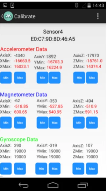
for the calculation of the pitch, roll and yaw angles. For each axis in Fig. 5, the current value is shown in black and the value stored when the respective button is pressed is shown in red. The gyroscope values are not being used; therefore its minimum and maximum values are not accurate.
Fig. 5. Sensor calibration panel of the smartphone application.
III. POSTURE CALCULATION
The three angles that describe the orientation of each sensor node on the respective body segment are pitch, roll and yaw. Pitch and roll are calculated using the normalized vector of the accelerometer values for each axis (ax, ay, az), whereas yaw is obtained by the horizontal components (Xh and Yh) of the Earth’s magnetic field. The equations representing the pitch, roll and yaw are, respectively:
(1)
(2)
Yaw
(3)
For the sensor node placed in the trunk, the pitch angle obtained in (1) provides the inclination of the trunk with respect to the horizontal plane. In order to obtain the trunk angle with respect to the bicycle, it is necessary to calculate the difference between the pitch and the angle of inclination of the bicycle, which is measured with the smartphone placed on the handlebar. This angle is calibrated before the start of the cycling activity by placing the bicycle in a horizontal terrain and pressing a button in the application which sets the angle to zero.
The other two sensor nodes are used to measure the knee
angle. For this purpose, one node is placed in the upper leg and the other is placed on the lower leg. The knee angle between these two body segments is given by (4).
!"## $ %&&'())*+,*- .%&&'
/01*+,*-2%())*+,*-22%/01*+,*-2 (4)
For the calculation of the orientation vectors vupperLeg and
vlowerLeg, the values of pitch, roll and yaw for both sensor nodes are calculated at each instant and multiplied by the rotation matrix in each axis. The rotation matrices for each axis are represented by Rx(α), Ry(θ) e Rz(τ) in (5), (6) and (7), respectively. α, θ e τ represent the angle of rotation about the x, y and z axis, respectively.
345 610 cos 4 < sin 40 0
0 sin 4 cos 4 ? (5)
3@5 6 cos @ 0 sin @0 1 0
< sin @ 0 cos @? (6)
A3B5 6cos @ < sin B 0sin B cos B 0
0 0 1? (7)
IV. RESULTS AND DISCUSSION
[image:4.595.307.548.405.524.2]In order to verify the results of the measurement of the angles calculated by the developed system during cycling activities, three sensor nodes were placed on the appropriate parts of the body of an athlete, as shown in Fig. 6.
Fig. 6. Sites of placement of the sensors on the athlete’s body: torso (left) and leg (right).
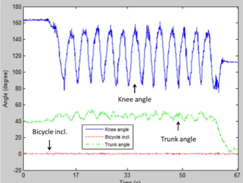
According to the convention adopted in this paper, the inclination of the bicycle during a climb corresponds to a positive angle, whereas during a descent this angle has negative values. Regarding the trunk angle, a forward reclining means positive values and reclining back generates negative values. The knee angle has a value of 180 degrees when the leg is fully extended, and as the cyclist bends the leg, the value of this angle decreases.
Fig. 7. Measurements of the trunk angle with variations on the angle of inclination of the bicycle along the time.
In order to evaluate the variation of the knee angle during a cycling activity, a second test was performed in a scenario where the athlete maintains an aerodynamic position in a horizontal terrain. The seat height in relation to the height of the pedals is an important factor to ensure maximum performance. The goal is that the athlete does not fully stretch his legs or otherwise bends them too much while pedaling. Fig. 8 presents the results of this test. Initially, without pedaling and with the leg almost fully extended, the knee angle has a value close to 160 degrees. After 8 s the athlete starts pedaling and the knee angle oscillates between 80 and 150 degrees until the athlete stops pedaling. During this time, the measured values for trunk angle are around 40 to 50 degrees. There is some variation in this angle during the test due to the effort exerted by the athlete during pedaling.
Fig. 8. Measurements of the knee and trunk angle while resting and pedaling on a horizontal terrain.
V. CONCLUSION
Cycling performance is significantly affected by the body posture. This paper proposed a system that monitors the posture of cyclists in real-time through the use of sensor nodes placed on the user’s body, which send the raw data via BLE to an Android smartphone, where it is processed in order to extract the posture angles. Unlike posture measurement systems based on cameras, this system does not require line of sight or controlled lighting conditions.
Due to its portability, it can be used either by amateur or professional athletes, during training or competition.
Currently, the gyroscopes of the sensor modules are not being used. Their data are acquired via SPI and are received the application, but are not used along with the accelerometer and magnetometer readings in the calculations. In the future the gyroscope readings may be used to compensate eventual measurement errors, in order to contribute to enhance the accuracy in the calculation of the posture.
In the future this system will be integrated into another developed Android application which provides a georeferenced database with measurements of several relevant cycling parameters, such as route, velocity, torque, cadence, power output and heart rate, and offers the functionality of visualization of the information in a map.
REFERENCES
[1] M. Patel and J. Wang, “Applications, challenges, and prospective in emerging body area networking technologies,” IEEE Wireless
Communications, vol. 17, no. 1, 2010, pp. 80-88.
[2] M. Chen, S. Gonzalez, A.Vasilakos, H. Cao and V. C. M. Leung, “Body area networks: A survey,” Mobile Networks and Applications, vol. 16, no. 2, 2011, pp. 171-193.
[3] M. C. Ashe et al., “Body position affects performance in untrained cyclists,” British Journal of Sports Medicine, vol. 37, no. 5, 2003, pp. 441-444.
[4] M. Egaña, S. Green, E. J. Garrigan and S. Warmington, “Effect of posture on high-intensity constant-load cycling performance in men and women,” European Journal of Applied Physiology, vol. 96, no. 1, 2003, pp. 1-9.
[5] W. Peveler, J. Pouders and P. Bishop, “Effects of saddle height on anaerobic power production in cycling,” Journal of Strenght and
Conditioning Research, v. 21, n. 4, 2007, pp. 1023-1027.
[6] W. Z. Khan, Y. Xiang, M. Y. Aalsalem and Q. Arshad, “Mobile phone sensing: A survey,” IEEE Communications Surveys & Tutorials, vol. 15, no. 1, 2013, pp. 402-427.
[7] N. D. Lane et al., “A survey of mobile phone sensing,” IEEE
Communications Magazine, vol. 48, no. 9, 2010, pp. 140-150.
[8] S. B. Eisenman et al., “BikeNet: A mobile sensing system for cyclist experience mapping,” ACM Transactions on Sensor Networks, vol. 6, no. 1, 2009, pp. 1-39.
[9] C. Outram, C. Ratti and A. Biderman, “The Copenhagen Wheel: An innovative electric bicycle system that harnesses the power of real-time information and crowd sourcing,” Proceedings of EVER’2010, Monaco, March 2010.
[10] W. Walker, A. L. P. Aroul and D. Bhatia, “Mobile health monitoring systems,” Proceedings of the 31st Annual International Conference of the IEEE EMBS, Minneapolis, Minnesota, USA, September 2009, pp. 5199-5202.
[11] C. Gomez, J. Oller and J.Paradells, “Overview and evaluation of Bluetooth low energy: an emerging low-power wireless technology,”
Sensors, vol. 12, no. 9, 2012, pp. 11734–11753.
[12] IEEE Std 802.15.4-2006, “Part 15.4: Wireless medium access control (MAC) and physical layer (PHY) specifications for low-rate wireless personal area networks (WPANs),” 2006.
[13] B. Mihajlov and M. Bogdanoski, “Overview and analysis of the performances of ZigBee-based wireless sensor networks,”
International Journal of Computer Applications, vol. 29, no. 12,
2011, pp. 28-35.
[14] Texas Instruments Datasheet, “2.4-GHz Bluetooth low energy system-on-chip, CC2540F128, CC2540F256,” June 2013.
[15] S. Johnsrud and T. Sundet, “CC111xFx, CC243xFx,CC251xFx and CC253xFx SPI,” Design Note DN113, Texas Instruments, 2009. [16] T. B. Moeslund, A. Hilton and V. Kruger, “A survey of advances in
vision-based human motion capture and analysis,” Computer Vision
[image:5.595.46.290.50.232.2] [image:5.595.48.288.460.640.2]