Abstract— The Operational Aircraft Maintenance Routing Problem (OAMRP) determines the route for each individual aircraft while incorporating the operational maintenance considerations. This problem is significant to airline companies as it determines the routes to be flown in real aspect life. Most of the studies incorporate some operational considerations and neglect the rest, resulting in generation of routes that are not feasible to be implemented in reality. In this paper, we study OAMRP, with two objectives. First, to propose a model that considers all operational maintenance requirements. For this purpose, we formulate a Mixed Integer Linear Programming (MILP) model by modifying the connection network. The proposed model is solved using commercial software, but only for small size problems. Second, a solution algorithm is developed to solve the model efficiently and quickly while tackling large scale problems. The performance of the proposed solution algorithm is validated based on real data obtained from EgyptAir carrier. The results demonstrate high quality solutions and significant savings in the computational time. This performance is evidence that the proposed model and solution method can be potential tool for solving real OAMRP.
Key words— Air transportation, Aircraft routing problem, Airline operations, Integer programming.
I. INTRODUCTION
n the last decade, the development of the aviation industry has shown radical economic growth. Similarly, the passenger demand is currently blooming and showing an increase of 5.2% from 2012 to 2013 [1], and it is expected to grow by 31% from 2012 to 2017 [2]. Despite this pleasant situation to the airline companies, airlines have a great challenge to assign more flights to their aircraft in order to cope with the demand growth, while considering the operational regulations. Managing that increased number of flights while keeping aircraft being maintained is a difficult operation for airline industry. For example, in 2010, 65000 U.S. airline flights should not take off because the aircraft did not receive proper maintenance, resulting in $28.2 million as a penalty cost against 25 U.S. airlines [3]. This investigation
Abdelrahman E.E. Eltoukhy is with the Department of Industrial and Systems Engineering, The Hong Kong Polytechnic University, Hong Kong, China. (e-mail: [email protected])
Felix T. S. Chan is with the Department of Industrial and Systems Engineering, The Hong Kong Polytechnic University, Hong Kong, China. (Tel: +852-2766-6605; fax: +852-2362-5267; e-mail: [email protected]) S. H. Chung is with the Department of Industrial and Systems Engineering, The Hong Kong Polytechnic University, Hong Kong, China. (e-mail: [email protected])
T. Qu is with the School of Electrical and Information Engineering, Jinan University (Zhuhai Campus), Zhuhai 519070, China
also presents the importance of maintenance since it was a cause, factor, or finding in 18 accidents, 43 deaths and 60 injuries. In this regard, the aircraft maintenance routing problem (AMRP), which is the main focus of this study, is very significant to airlines in that it generates maintenance feasible routes for each aircraft to be flown in reality.
AMRP is one of the most studied problems in the literature with two main focuses: tactical and operational. Regarding the tactical side, it aims to generate specific rotations for each aircraft in the fleet, while neglecting many of the operational maintenance constraints. That generated rotations are kept repeated by each aircraft in the fleet. Since using single rotation for each aircraft is not applicable due to lack of considering operational maintenance constraints. Thus, AMRP is studied at more operational focus, which aims to specify maintenance feasible routes for each aircraft in the fleet. A route is maintenance feasible when it satisfies the operational maintenance requirements such as the restrictions on the total cumulative flying-time, number of maintenance operations every four days, restrictions on the total number of take-offs, and the workforce capacity of each maintenance station.
Focusing on the tactical side of AMRP, Kabbani and Patty [4] formulated AMRP as a set-partitioning model to find feasible routes or lines of flight (LOF) for 3-day AMRP. The use of (LOF) was expanded by Gopalan and Talluri [5] in order to solve the k-days AMRP. They developed a polynomial time algorithm in order to determine maintenance feasible routes for aircrafts for 3-day AMRP. 4-day AMRP was handled by Talluri [6] who developed an effective heuristic to solve their problem, which was shown to be NP-hard. Clarke, et al. [7] adopted lagrangian relaxation to solve their proposed model that aimed at finding feasible maintenance rotations that yields the maximum through value. The through value can be defined as the additional profit gained through connecting some specific flights. More recently, Liang, et al. [8] developed a new rotation-tour time-space network for AMRP, and proposed new integer linear programming (ILP) according to their network. The proposed model was solved using commercial software.
Based on operational side of AMRP, which is called OMARP, Sriram and Haghani [9] presented an ILP model that considered only two among the four operational maintenance constraints. Firstly, one maintenance visit every four days and secondly, the workforce capacity constraints. An effective heuristic was proposed and the model was solved in a reasonable computational time when compared with CPLEX. In that study, the authors extended their model
Optimization Model and Solution Method for
Operational Aircraft Maintenance Routing
Problem
Abdelrahman E.E. Eltoukhy, Felix T. S. Chan, S. H. Chung and T. Qu
and considered the cumulative flying hour; however, the authors did not attempt to solve it because of its high complexity. It is worth mentioning that the extended model is quite simple compared to our model proposed in this paper. Sarac, et al. [10] formulated OAMRP as a set-partitioning model that considered only maximum flying hour and workforce capacity, as maintenance constraints, and neglected the rest. The proposed model was solved by the adoption of column generation technique. Recently, Haouari, et al. [11] developed non-linear model for OAMRP, while considering three maintenance constraints simultaneously. These constraints are, one visit every four days, the maximum flying hours, and the maximum number of take-offs. They linearized their model by using reformulation-linearization technique that provided high quality solutions while solving the daily version of OAMRP. Başdere and Bilge [12] developed ILP model for OAMRP, while considering only maximum flying hour as a maintenance constraint. The proposed model was solved by using both branch-and-bound (B&B) and compressed annealing (CA). The authors reported that compressed annealing outperformed branch-and-bound for large scale problems, and it could find feasible solutions in minutes, which is important for the airline industry.
The focus of this paper is the operational side of AMRP and the contribution of this work is as follow. Firstly, from the above list of work studies, we can see that set-partitioning or set covering based formulations are the most commonly used approach at which the number of feasible routes grow exponentially with the number of flights. However, a drawback of this approach is that it generates an exponential number of routes which is difficult to be solved. In this paper, in contrast to set-partitioning approach that needs sophisticated solutions, we propose a formulation that uses polynomial number of variables and constraints, which can handle real and large scale problem easily. Secondly, it is also observed that most of the OAMRP considered some maintenance constraints while neglecting the rest. To our best knowledge, the models by Barnhart, et al. [13] and Haouari, et al. [11] are the only models that considered three maintenance constraints (one maintenance visit every four days, maximum flying hours and maximum number of take-offs). However, these studies failed to consider the workforce capacity constraints, which is very important. Imagine, if, for instance, the model neglects workforce capacity and schedules four aircraft for maintenance in one station with insufficient workforce capacity. It is highly probable to face two situations. First, the wait time of some of the aircraft will be prolonged in order to receive the maintenance, leading to cancellation of subsequent scheduled flights. Second, the wait time can be avoided if more hands and/or resources are deployed to handle the excess traffic. In both cases, additional cost will be incurred for not considering the workforce capacity. Therefore, the viability of this constraint necessitates its addition to the OAMRP. Since our polynomial formulation is scalable compared to set-partitioning formulations, so all four maintenance constraints can be considered in one model enabling it to be easily implemented in the real life situation. In addition to these contributions, we propose an efficient solution method, which generates the high quality solutions for large scale test
instances in a short computational time allowing it to handle real situations in the airline industry.
In this paper, we focus on the operational side of AMRP, and our aim is twofold. Firstly, to develop an OAMRP model that considers all the maintenance constraints in one model. For this purpose, a new MILP is proposed for OAMRP. Secondly, to propose an effective solution algorithm that can solve the OAMRP while tackling large scale instances that cannot be solved by using CPLEX. The performance of the proposed algorithm is validated with respect to exact solutions obtained from CPLEX for small size problems, whereas the best upper bound is used to assess the performance while solving large scale problems.
The rest of the paper is organized as follow. In section 2, we describe the OAMRP and the new MILP formulation is proposed. The effective solution algorithm is proposed in section 3. In section 4, the computational experimental results for real cases are provided. We conclude in the final section of this paper.
II. THE MATHEMATICAL MODEL FORMULATION
Given a schedule of flight legs, our proposed OAMRP is to generate maintenance feasible routes to be flown by each aircraft so that the total potential profit is maximized. To generate maintenance feasible routes, they should satisfy the operational maintenance requirements mandated by Federal Aviation Administration (FAA), which are, the restrictions on the total cumulative flying-time, number of maintenance operations every four days, restrictions on the total number of take-offs, and the workforce capacity of each maintenance station.
The objective function of the proposed model is to maximize the total potential profit, which is the difference between the through value or revenue and the penalty cost. Through value is the revenue that comes from the through connects which attract the passengers. On the other hand, the penalty cost is the cost paid by the airlines while neglecting maintenance workforce capacity as explained before.
The multi-commodity network flow based MILP formulation presented in this paper the model formulation that is based on the connection network, which is commonly used network for AMRP, as shown in [5] and [11]. Nodes of the network represent the flight legs and maintenance stations, whereas, the arcs represent the possible connections among flight legs, and the connections between flight legs and maintenance stations. In this network, there are three types of arcs. Firstly, the ordinary arc that connects between two flight legs. Secondly, the maintenance arc, which connects between the flight leg and the maintenance station. Lastly, the auxiliary arcs, which connects between the maintenance station and the flight leg. Auxiliary arcs play the role of going back to use the ordinary arcs after finishing the maintenance operations.
To formalize the representation of the proposed OAMRP, we first define the notations that are frequently used throughout this chapter, before giving the detailed formulation.
First, we start by listing the sets and the indices associated with each set.
𝑚 ∈ 𝑀𝑇: Set of maintenance stations. 𝑎 ∈ 𝐴: Set of airports.
𝑣 ∈ {1,2, … , 𝑉}: Number of maintenance operations that at least should be performed by each aircraft.
{𝑜, 𝑡}: Dummy source and sink nodes of the network. Next, the parameters are defined as follow.
𝐷𝑇𝑖: Departure time of flight leg 𝑖. 𝐴𝑇𝑖: Arrival time of flight leg 𝑖. 𝑇𝑅𝑇: Turn-around time.
𝑂𝑖𝑎: Origin binary indicator of flight leg 𝑖 such that 𝑂𝑖𝑎= 1 if the origin of flight leg 𝑖 and the airport 𝑎 are the same, and 0 otherwise.
𝐷𝑖𝑎: Destination binary indicator of flight leg 𝑖 such that 𝐷𝑖𝑎= 1 if the destination of flight leg 𝑖 and the airport 𝑎 are the same, and 0 otherwise.
𝐹𝑇𝑖: Flight duration of flight leg 𝑖.
𝑏𝑖𝑗: Through value of the connection between flight legs 𝑖 and 𝑗.
𝑇𝑚𝑎𝑥: Maximum flying time between two successive maintenance operations.
𝐶𝑚𝑎𝑥 : Maximum number of take-offs between two successive maintenance operations.
𝑀𝑃𝑚: Workforce group that available in maintenance station 𝑚.
𝐸𝑇𝑚: Close time for the maintenance station 𝑚.
𝑀𝑏𝑚𝑎: Maintenance binary indicator of maintenance station 𝑚 such that 𝑀𝑏𝑚𝑎 = 1 if the maintenance station 𝑚 located at airport 𝑎, and 0 otherwise.
𝑀𝐴𝑇: Time required to perform the maintenance operation.
𝐾𝑇: Total number of aircraft used to cover the flight legs. 𝑉: The number of maintenance visits to be performed by each aircraft, which is calculated by using the following rule; 𝑉 = ∑𝑖∈𝑁𝐹𝐷𝑇𝑖⁄𝑇𝑚𝑎𝑥 𝐾𝑇.
𝑀: A considerable big number.
𝑃𝐶𝑘𝑚: the penalty cost paid if the aircraft 𝑘 has been assigned to maintenance station 𝑚 that does not have enough workforce capacity.
The decision variables are:
𝑥𝑖𝑗𝑘𝑣∈ {0,1}, it equals 1 if flights legs 𝑖 and 𝑗 are covered by aircraft 𝑘 before performing maintenance operation number 𝑣 and 0 otherwise.
𝑦𝑖𝑚𝑘𝑣∈ {0,1}, it equals 1 if aircraft 𝑘 covers flight legs 𝑖 then perform maintenance operation number 𝑣 at maintenance station 𝑚 and 0 otherwise.
𝑧𝑚𝑗𝑘𝑣∈ {0,1}, it equals 1 if aircraft 𝑘 covers flight legs 𝑗 after performing maintenance operation number 𝑣 at maintenance station 𝑚 and 0 otherwise.
𝑅𝑇𝐴𝑀𝑘𝑣 > 0, it is the ready time for aircraft 𝑘 to continue covering another flight legs after performing the maintenance operation number 𝑣. This decision variable is not required to be integer, as the time might be fractional.
Based on the above notations, the mathematical model of OAMRP can be written as follow:
Max 𝑍 =
∑𝑘∈𝐾∑𝑖∈𝑁𝐹∑𝑗∈𝑁𝐹∑𝑣∈𝑉𝑏𝑖𝑗𝑥𝑖𝑗𝑘𝑣−
∑𝑚∈𝑀𝑇∑𝑘∈𝐾∑𝑖∈𝑁𝐹∑𝑣∈𝑉𝑃𝐶𝑘𝑚(𝑦𝑖𝑚𝑘𝑣− 𝑀𝑃𝑚)+ (1) Subject to
∑ 𝑘∈𝑘(∑𝑗∈𝑁𝐹∪{𝑡}∑𝑣∈𝑉𝑥𝑖𝑗𝑘𝑣+ ∑𝑚∈𝑀𝑇∑𝑣∈𝑉𝑦𝑖𝑚𝑘𝑣)=
1 ∀ 𝑖 ∈ 𝑁𝐹 (2) ∑𝑗∈𝑁𝐹𝑥𝑜𝑗𝑘𝑣+ ∑𝑚∈𝑀𝑇𝑦𝑜𝑚𝑘𝑣= 1 ∀ 𝑘 ∈ 𝑘, ∀ 𝑣 ∈ 𝑉 (3) ∑𝑖∈𝑁𝐹𝑥𝑖𝑡𝑘𝑣+ ∑𝑚∈𝑀𝑇𝑧𝑚𝑡𝑘𝑣= 1 ∀ 𝑘 ∈ 𝑘, ∀ 𝑣 ∈ 𝑉 (4) ∑𝑗∈𝑁𝐹∪{𝑜}𝑥𝑗𝑖𝑘𝑣+ ∑𝑚∈𝑀𝑇𝑧𝑚𝑖𝑘𝑣= ∑𝑗∈𝑁𝐹∪{𝑡}𝑥𝑖𝑗𝑘𝑣+
∑𝑚∈𝑀𝑇𝑦𝑖𝑚𝑘𝑣 ∀ 𝑖 ∈ 𝑁𝐹, ∀𝑘 ∈ 𝑘 , ∀ 𝑣 ∈ 𝑉 (5) ∑𝑗∈𝑁𝐹∑𝑣∈𝑉𝑦𝑗𝑚𝑘𝑣= ∑𝑗∈𝑁𝐹∪{𝑡}∑𝑣∈𝑉𝑧𝑚𝑗𝑘𝑣 ∀𝑚 ∈
𝑀𝑇, ∀𝑘 ∈ 𝑘 (6) 𝐴𝑇𝑖+ 𝑇𝑅𝑇 − 𝐷𝑇𝑗 ≤ 𝑀(1 − 𝑥𝑖𝑗𝑘𝑣) ∀ 𝑖 ∈ 𝑁𝐹, ∀∈ 𝑁𝐹, ∀𝑘 ∈ 𝑘, ∀𝑣 ∈ 𝑉 (7) ∑ 𝑘∈𝑘𝑥𝑖𝑗𝑘𝑣≤ ∑𝑎∈𝐴𝐷𝑖𝑎𝑂𝑗𝑎 ∀ 𝑖 ∈ 𝑁𝐹, ∀𝑗 ∈ 𝑁𝐹, ∀𝑣 ∈ 𝑉 (8) 𝐴𝑇𝑖+ 𝑀𝐴𝑇 − 𝐸𝑇𝑚≤ 𝑀(1 − 𝑦𝑖𝑚𝑘𝑣) ∀ 𝑖 ∈ 𝑁𝐹, ∀𝑚 ∈ 𝑀𝑇, ∀𝑘 ∈ 𝑘, ∀𝑣 ∈ 𝑉 (9) ∑ 𝑘∈𝑘𝑦𝑖𝑚𝑘𝑣≤ ∑𝑎∈𝐴𝐷𝑖𝑎𝑀𝑏𝑚𝑎 ∀ 𝑖 ∈ 𝑁𝐹, ∀𝑚 ∈
𝑀𝑇, ∀𝑣 ∈ 𝑉 (10) ∑ 𝑘∈𝑘𝑧𝑚𝑗𝑘𝑣 ≤ ∑𝑎∈𝐴𝑀𝑏𝑚𝑎 𝑂𝑗𝑎 ∀𝑚 ∈ 𝑀𝑇, ∀𝑗 ∈
𝑁𝐹, ∀𝑣 ∈ 𝑉 (11) 𝑅𝑇𝐴𝑀𝑘𝑣 = ∑𝑖∈𝑁𝐹∪{𝑜}∑𝑚∈𝑀𝑇𝐸𝑇𝑚𝑦𝑖𝑚𝑘𝑣 ∀𝑘 ∈ 𝑘, ∀𝑣 ∈ 𝑉 (12) 𝑅𝑇𝐴𝑀𝑘𝑣− 𝐷𝑇𝑗 ≤ 𝑀(1 − 𝑧𝑚𝑗𝑘𝑣) ∀𝑚 ∈ 𝑀𝑇, ∀𝑗 ∈ 𝑁𝐹, ∀𝑘 ∈ 𝑘, ∀𝑣 ∈ 𝑉 (13) ∑𝑖∈𝑁𝐹∪{𝑜}∑𝑗∈𝑁𝐹𝑥𝑖𝑗𝑘𝑣≤ 𝐶𝑚𝑎𝑥 ∀𝑘 ∈ 𝑘, ∀𝑣 ∈ 𝑉 (14) ∑𝑖∈𝑁𝐹∪{𝑜}∑𝑗∈𝑁𝐹𝐷𝑇𝑗𝑥𝑖𝑗𝑘𝑣 ≤𝑇𝑚𝑎𝑥 ∀𝑘 ∈ 𝑘, ∀𝑣 = 1 (15) ∑𝑖∈𝑁𝐹∑𝑗∈𝑁𝐹𝐷𝑇𝑗𝑥𝑖𝑗𝑘𝑣+
∑𝑚∈𝑀𝑇∑𝑗∈𝑁𝐹𝐷𝑇𝑗𝑧𝑚𝑗𝑘𝑣≤ 𝑇𝑚𝑎𝑥 ∀𝑘 ∈ 𝑘, ∀𝑣 ∈ 𝑉/{1} (16) ∑𝑖∈𝑁𝐹∑𝑚∈𝑀𝑇∑𝑣∈𝑉𝑦𝑖𝑚𝑘𝑣= 𝑉 ∀𝑘 ∈ 𝑘 (17) 𝑉 ≥ 1 (18) ∑𝑖∈𝑁𝐹∪{𝑜}∑𝑘∈𝐾∑𝑣∈𝑉𝑦𝑖𝑚𝑘𝑣 ∀ 𝑚 ∈ 𝑀𝑇 (19) 𝑥𝑖𝑗𝑘𝑣∈ {0,1} ∀ 𝑖 ∈ 𝑁𝐹, ∀𝑗 ∈ 𝑁𝐹, ∀𝑘 ∈ 𝑘, ∀𝑣 ∈ 𝑉 (20) 𝑦𝑖𝑚𝑘𝑣∈ {0,1} ∀ 𝑖 ∈ 𝑁𝐹, ∀𝑚 ∈ 𝑀𝑇, ∀𝑘 ∈ 𝑘, ∀𝑣 ∈ 𝑉 (21) 𝑧𝑚𝑗𝑘𝑣∈ {0,1} ∀ 𝑚 ∈ 𝑀𝑇, ∀ 𝑗 ∈ 𝑁𝐹, ∀𝑘 ∈ 𝑘, ∀𝑣 ∈ 𝑉 (22) 𝑅𝑇𝐴𝑀𝑘𝑣 > 0 ∀𝑘 ∈ 𝑘, ∀ ∈ 𝑉 (23)
The objective function (1) is the maximization of the total
profit, which is the through value (revenue) minus total penalty cost. Constraints (2), (3), and (4) describe the coverage constraints. Constraints (2) indicate that each flight leg must be covered exactly by one aircraft. The constraints in (3) ensure that each aircraft starts its route, whereas constraints (4) guarantee the route completion.
In order to keep the circulation of the aircraft throughout the network, the balance constraints (5) and (6) are formulated. Constraints (5) keep the balance when aircraft covers flight leg nodes. These constraints indicate that if the aircraft covers flight leg either by using ordinary arc or auxiliary arc, then the next flight must be covered either by using ordinary arc or maintenance arc. Same as constraints (5), constraints (6) keep the balance for maintenance nodes.
In order to connect two flight legs by using same aircraft, that connection should be feasible in terms of time and place considerations, as described by constraints (7) and (8). Constraints (7) indicate the time constraints such that the aircraft can cover two successive flight legs, if the arrival time of the first one plus turn-around time is less than or equal the departure time of second one. On the other hand, place constraints in (8) ensure that the aircraft can cover two consecutive flight legs, if the destination of the first one and origin of the second one are the same.
consider the place and time issues for the last covered flight leg and the potential visited maintenance station. These considerations are summarized by constraints (9) and (10). Constraints (9) describe the time constraints such that the aircraft can visit the maintenance station, if the arrival time of the last covered flight leg plus the time needed to perform the maintenance, is less than or equal the time when the maintenance station will be closed. Place constraints in (10) ensure that the aircraft can visit the maintenance station, if the destination airport of the last covered flight leg and the location of maintenance station are the same.
After finishing the maintenance operation, the aircraft should move from maintenance station and cover next flight leg by using auxiliary arc. For this purpose, constraints (11), (12), and (13) are cast, which represent time and place considerations for the maintenance station and the next flight to be covered. Constraints (11) constitute the place constraints such that the aircraft can cover next flight leg after performing the maintenance, if the origin airport of that flight leg and the location of the maintenance station are the same. Time constraints in (13) guarantee that the aircraft can cover next flight leg after maintenance operation, if the departure time of the next flight leg is less than or equal ready time of aircraft 𝑅𝑇𝐴𝑀𝑘𝑚, which is determined by constraints (12).
It must be noted that the coverage and balance constraints do not enforce the aircraft that needs maintenance to undergo maintenance operation. Therefore, the operational restrictive constraints (14), (15), (16), (17) and (18) are cast. Constraints (14) guarantee that number of take-offs between maintenance operations does not exceed the maximum take-offs. Similarly, constraints (15) and (16) are the restrictive constraints regarding the accumulated flying time between maintenance operations. Constraints (17) are formulated to ensure that the number of maintenance visits by each aircraft is equal to that beginning predetermined number of visits. Since the planning horizon in our study is 4-day, and the constraint (18) ensure that the number of maintenance visit is larger than one, so the first operational maintenance constraint (one visit every four days) that is mandated by FAA, is satisfied.
Before preparing appropriate maintenance visit for the aircraft, it is very important to check whether the maintenance has enough workforce capacity or not. Therefore, workforce capacity constraints are cast in constraints (19), in order to avoid overcapacity problem. These constraints ensure that the number of maintained aircraft does not exceed the maintenance workforce capacity. Finally, the constraints (20) - (23) define the domain of the decision variables.
The scope of the proposed model is described as follow: The planning horizon is 4 days.
The model only considers the existing maintenance stations and there is no recommendation for constructing new stations.
The maintenance stations are located in the hub airports.
The number of man-power groups in each maintenance station is deterministic.
All the maintenance operations discussed in this paper is Type A maintenance check, which is commonly considered one in the literature.
III. SOLUTION APPROACH
In this section, we propose an efficient solution algorithm for solving the proposed model. The algorithm can be summarized in two points. First, we prepare sub-routes that maximize the profit, while considering the coverage, balance, time and place constraints as shown by Eq. (2)-(8). Then, second, the algorithm keeps trying to construct complete routes using that pre-determined sub-routes, while considering all the maintenance constraints as described by Eq. (9)-(23). The steps of the algorithm are explained as follow:
Step 0: Prepare a list that represent the aircraft (𝐾), and make another list to represent the flight leg nodes (𝑁𝐹). Step 1: Determine the number of maintenance operations (𝑉)
to be performed by each aircraft in the fleet by using the following rule; 𝑉 = ∑𝑖∈𝑁𝐹𝐷𝑇𝑖⁄𝑇𝑚𝑎𝑥 𝐾𝑇.
Step 2: Split the list of 𝑁𝐹 into two lists. First list is called star list (𝑆𝐿), it contains the through connects, thus that list is given high priority during the route construction. The second list is called normal list (𝑁𝐿). Since NL contains the remaining flight legs, so it is given low priority during route construction. To do that split, for each pair of flight legs in the 𝑁𝐹 list, the connection time between the pair’s flight legs is calculated. If the connecting time of the pair has a through value. Then, this pair is a through connect and has to be stored in 𝑆𝐿 and the pair’s flight legs are removed from 𝑁𝐹. Otherwise, store the rest of the flight legs in 𝑁𝐿. Step 3: Use 𝑆𝐿 in order to construct another list called
sub-routes list (𝑆𝑅𝐿). Each sub-route is constructed by connecting two pairs from 𝑆𝐿. That two pairs can be connected, especially when the ending flight of first pair and the starting flight of the second pair are the same. Each constructed sub-route is stored in 𝑆𝑅𝐿. Of course, not all the pairs can be connected, so the remaining non-connected pairs should be stored in 𝑆𝑅𝐿. So, by the end of this step, we have two three lists, 𝐾, 𝑆𝑅𝐿, and 𝑁𝐿.
Step 4: Initialize number of iterations=1.
Step 5: Pick 𝑘th aircraft from 𝐾 list. If the list is empty, then go to step 8, otherwise go to step 6.
Step 6: Start to construct the complete route for the 𝑘th aircraft by using backward and forward insertion approaches, while considering the maintenance constraints shown in Eq. (14) -(19). In order to conduct the backward insertion approach, we follow the following sub-steps:
Step a: Pick one element from 𝑆𝑅𝐿 randomly, because it contains the pairs with high priority. If 𝑆𝑅𝐿 is empty, then low priority 𝑁𝐿 is used for picking that element. This picked element is considered the first part of the constructed route.
Step b: For the picked element, identify the staring flight leg, which is either the first flight leg if the element is picked from 𝑆𝑅𝐿, or it is the element itself if it is selected from 𝑁𝐿.
flight legs from 𝑁𝐿. Firstly, we scan through 𝑆𝑅𝐿 due to its high priority. As we mentioned before, if 𝑆𝑅𝐿 is empty, we use the second option by scanning through 𝑁𝐿. The scan is conducted while considering constraints described in Eq. (7) and (8). If both 𝑆𝑅𝐿 and 𝑁𝐿 are empty, then go to step h, otherwise go to step d.
Step d: Identify the list of potential elements. Then, calculate the connecting time and the corresponding through value for each potential element. In the case of no potential elements, then go to step h, otherwise go to step e.
Step e: Select the element with the highest through value, while considering the maintenance constraints stated in Eq. (14) -(19).
Step f: Add the selected element to the route, and remove that element from 𝑆𝑅𝐿 or 𝑁𝐿.
Step g: Update the starting leg, then go to step c. Step h: Terminate the backward insertion approach. After conducting the backward insertion, we start conducting the forward insertion approach. First, we identify the ending flight leg for the element picked in step b. The ending flight leg is either the last flight leg if the element is picked from 𝑆𝑅𝐿, or it is the element itself if it is selected from 𝑁𝐿. Second, we follow the same steps (c)-(h) but by inserting the suitable elements forwardly to the element that is picked in step a.
Step 7: Set the end to route that constructed for the 𝑘th aircraft, remove the aircraft 𝑘 from the 𝐾 list, and go to step 5.
Step 8: Calculate the solution of the current iteration, compare with the solution of the previous iteration, and save the best solution.
Step 9: Check the stopping criteria whither it is satisfied or not. If it is not satisfied, then increment the iteration number, update the empty lists of K, 𝑆𝑅𝐿, and 𝑁𝐿 by using the same lists produced by the end of step 3 and go to step 5. If the stopping criteria satisfied, then stop. In our solution algorithm, the stopping criteria is satisfied when the current solution equals the exact solution for small test cases, or the current solution equal the best upper bound for large test cases, or the number of iterations equal the maximum number of iterations. In all test instances, the maximum number of iterations is set at 1000.
One of the obvious questions after using that solution algorithm is how to evaluate the performance of the proposed solution algorithm. To make this evaluation, we propose comparing the solution obtained from our efficient algorithm with the optimal solution generated by CPLEX, especially for small size test instances. In the case of large size test instances, we propose using the best upper bound (𝑈𝐵) obtained from CPLEX as criteria to assess the performance of the proposed solution algorithm, since CPLEX fails to even produce feasible solution within 6 hours.
IV. COMPUTATIONAL RESULTS
In this section, we present the computational results obtained from the proposed algorithm and those obtained directly from solving the MILP formulations. The MILP
formulation is solved by using CPLEX 12.1. This computational study aims to verify the effectiveness of the proposed solution algorithm while solving real and large OAMRP. The experiments of this study were carried out using real flight schedule data sets from the EgyptAir carrier. All the test cases were carried out on an Intel i7 2.50 GHz laptop with 8 GB of RAM memory running on Windows 10 operating system. The proposed algorithm in this study was coded in Matlab R2014a.
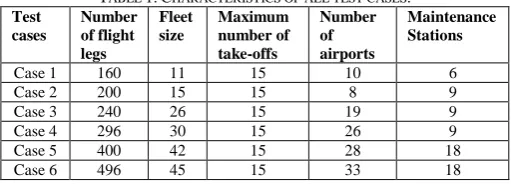
A. Test instances
The six test instances used in our experiments are real schedules, which were constructed by extracting ten flight schedules in which each schedule is covered by different fleet. Detailed information about the test instances are presented in table 1.
For all test instances, we assume that the turn-around time 𝑇𝑅 is 45 minutes, the maximum flying time 𝑇𝑚𝑎𝑥 is 40 hours, and the time required for maintenance operation is 8 hours. Also, it is assumed by the EgyptAir carrier that the through value occurs if the connecting time between two consecutive flight legs, covered by the same aircraft, is between 45 minutes and 1.5 hour. In this study, all the through values are provided by EgyptAir carrier. Also, the penalty cost is assumed to be 500 $ for each aircraft.
TABLE 1:CHARACTERISTICS OF ALL TEST CASES. Test
cases
Number of flight legs
Fleet size
Maximum number of take-offs
Number of airports
Maintenance Stations
Case 1 160 11 15 10 6
Case 2 200 15 15 8 9
Case 3 240 26 15 19 9
Case 4 296 30 15 26 9
Case 5 400 42 15 28 18
Case 6 496 45 15 33 18
B. Performance characteristics while solving small size
test instances
Table 2 shows the comparison of the results obtained from the CPLEX and those obtained from the proposed solution algorithm for the cases 1 through 3, which are considered a small size test instances. The first two columns of the table represent the results of CPLEX, which are the exact or optimal solution (𝑍∗) and the computational time 𝐶𝑃𝑈(𝑠). The remaining columns of the table summarize the results of the proposed algorithm. 𝑍𝑏𝑒𝑠𝑡and 𝑍̅ columns report the best solution and the average solution, respectively, whereas the 𝐶𝑃𝑈(𝑠) column records the computational time. In order to assess the performance of the proposed algorithm, we use the optimality gap (%Difference) as a performance indicator. %Difference is computed by (𝑍∗− 𝑍̅)/ 𝑍∗.
TABLE 2:PERFORMANCE CHARACTERISTICS OF CPLEX AND PROPOSED ALGORITHM WHILE SOLVING SMALL SIZE CASES
Test cases
CPLEX Proposed algorithm %Difference
𝑍∗ 𝐶𝑃𝑈(𝑠) 𝑍
𝑏𝑒𝑠𝑡 𝑍̅ 𝐶𝑃𝑈(𝑠)
Case 1 22000 372 22000 21852 1.56 0.67 Case 2 42667 633 42666 42542 1.61 0.29 Case 3 34083 9130 34083 33899 2.64 0.54
[image:5.595.299.555.367.459.2]computational time for both approaches in table 2 reveals that the proposed algorithm is much faster than CPLEX since it produces the solution within at most 3 seconds while the CPLEX needs up to 2.5 hours to solve the same problem.
It is clear that solving test cases with the size up to 240 flights and 26 aircraft is not large scale enough to discuss the efficiency of the proposed algorithm; however, with the small size test instances, we are able to compare the performance with the exact methods as shown in this section. In the large size test instances, the CPLEX fails to even produce feasible solution within 6 hours due to the size of problem and then computing the optimality gap becomes immeasurable. Therefore, we propose using the gap (%GAP) to be the performance indicator while solving the large cases. %GAP is the difference between the best upper bound (𝑈𝐵) obtained from CPLEX and the average solution obtained from the proposed algorithm. On the other hand, testing the proposed algorithm in large size test instances is necessary to show its applicability to handle real life problem. For this purpose, we perform computational experiments using large size test instances in the next section.
C. Performance characteristics while solving large size
test instances
In this section, the proposed algorithm is tested on larger instances to assess its applicability and scalability to solve real life problems. The experiments in this section are carried out by using the cases 4 throughout case 6. The summary of the proposed algorithm results can be seen in table 3, in which we report the same statistics as in table 2.
We can see from table 3 that performance of the proposed algorithm still produces high quality solutions in a reasonable computational time. Starting with the solution quality, it is noticed that 𝑍𝑏𝑒𝑠𝑡 reaches 𝑈𝐵 in all cases, whereas 𝑍̅ deviates from 𝑈𝐵 with a %GAP of around 0.55%. It is worthy note that the %GAP produced in all cases is less than 0.7%. Regarding the computational time, it is clear cut that the proposed algorithm is very fast. For the largest test case, which is case 6, it is solved in less than 12 seconds.
TABLE 3:PERFORMANCE CHARACTERISTICS OF CPLEX AND PROPOSED ALGORITHM WHILE SOLVING LARGE SIZE CASES
Test cases
𝑼𝑩 Proposed algorithm %GAP
𝑍𝑏𝑒𝑠𝑡 𝑍̅ 𝐶𝑃𝑈(𝑠)
Case 4 60333 60333 59997 2.57 0.55
Case 5 72583 72583 72097 9.22 0.66
Case 6 111000 111000 110425 11.22 0.52
These experiments show that the proposed algorithm can be used efficiently to solve real life problems as it handles large size test instances and provides profitable solution in a very short computational time.
V. CONCLUSIONS
In this paper, we presented a new MILP model for OAMRP while considering all the operational maintenance constraints along with effective solution algorithm.
In terms of solution methods, first, we solved the model using commercial software (e.g. CPLEX) that can produce exact solutions for only small size test instances in a long computational time. In order to handle large size test instances, we proposed an effective algorithm that can find
high quality solution quickly. Regarding the proposed algorithm, it can handle small size test instances easily, as it produces best solutions that equal to the exact solution, whereas the average solutions deviate from optimality by at most 0.67%. With respect to the computational time, the proposed algorithm improves the computational time significantly, since it can find the solution within 3 seconds while the CPLEX needs up to 2.5 hours to solve the problem. The proposed algorithm, on the other hand, can handle large scale test instances efficiently, where CPLEX fails to even produce feasible solution. It can find the best solutions that equal to the upper bound, whereas the average solutions deviate from upper bound by at most 0.67%. With respect to the computational time, it shows quick performance as it found the solution for the largest case in less than 12 seconds.
ACKNOWLEDGMENT
The work described in this paper was supported by grants from the Research Grants Council of the Hong Kong Special Administrative Region, China (Project No. PolyU 15201414); The Natural Science Foundation of China (Grant No. 71471158); The Research Committee of Hong Kong Polytechnic University (Project Numbers G-UB03; G-YBFD; G-UA4F; G-YBN1) and under student account code RTYN.
REFERENCES
[1] ICAO, "2013 ICAO Air Transport Results confirm robust Passenger Demand, sluggish Cargo Market " 2014.
[2] IATA. Airlines Expect 31% Rise in Passenger Demand by 2017.
[Online]. Available:
http://www.iata.org/pressroom/pr/pages/2013-12-10-01.aspx [3] G. Stoller, "Planes with maintenance problems have flown anyway," in
USA TODAY, ed, 2010.
[4] N. M. Kabbani and B. W. Patty, "Aircraft routing at American airlines," in In Proceedings of the 32nd annual symposium of
AGIFORS, Budapest, Hungary, 1992.
[5] R. Gopalan and K. T. Talluri, "The Aircraft Maintenance Routing Problem," Operations Research, vol. 46, pp. 260-271, April 1998. [6] K. T. Talluri, "The Four-Day Aircraft Maintenance Routing Problem,"
Transportation Science, vol. 32, pp. 43-53, Feb. 1998.
[7] L. Clarke, E. Johnson, G. Nemhauser, and Z. Zhu, "The aircraft rotation problem," Annals of Operations Research, vol. 69, pp. 33-46, Jan. 1997.
[8] Z. Liang, W. A. Chaovalitwongse, H. C. Huang, and E. L. Johnson, "On a New Rotation Tour Network Model for Aircraft Maintenance Routing Problem," Transportation Science, vol. 45, pp. 109-120, Feb. 2011.
[9] C. Sriram and A. Haghani, "An optimization model for aircraft maintenance scheduling and re-assignment," Transportation Research
Part A: Policy and Practice, vol. 37, pp. 29-48, Jan. 2003.
[10] A. Sarac, R. Batta, and C. M. Rump, "A branch-and-price approach for operational aircraft maintenance routing," European Journal of
Operational Research, vol. 175, pp. 1850-1869, Dec. 2006.
[11] M. Haouari, S. Shao, and H. D. Sherali, "A Lifted Compact Formulation for the Daily Aircraft Maintenance Routing Problem,"
Transportation Science, vol. 47, pp. 508-525, Nov. 2013.
[12] M. Başdere and Ü. Bilge, "Operational aircraft maintenance routing problem with remaining time consideration," European Journal of
Operational Research, vol. 235, pp. 315-328, May 2014.