Satellite Based Turbo-Coded, Blind-Equalized
4-QAM and 16-QAM Digital Video Broadcasting
Chee-Siong Lee, Spyros Vlahoyiannatos, and Lajos Hanzo, Senior Member, IEEE
Abstract—The Pan-European Digital Satellite Video
Broad-casting (DVB-S) system’s performance is characterized and improved with the aid of turbo coding and multi-level modula-tion. Specifically, various configurations of blind equalizers and convolutional as well as turbo codecs operating at different code rates were investigated. The standard system’s performance was improved upon replacing the conventional convolutional codec by a turbo codec. Lastly, the feasibility of employing blind equalized 16-level modulation within the DVB-S system is demonstrated, potentially doubling the available bitrate and hence improving the associated video quality at the cost of a higher Signal-to-Noise Ratio (SNR) requirement. This extra transmitted power require-ment can be eliminated upon invoking the more complex turbo codec, which requires lower transmitted power for attaining the same performance as the standard convolutional codes.
Index Terms—Blind equalization, digital video broadcasting,
DVB, DVB-S, QAM, quadrature amplitude modulation.
I. BACKGROUND ANDMOTIVATION
I
N RECENT years three harmonized Digital Video Broad-casting (DVB) standards have emerged in Europe for terrestrial [1], cable-based [2], and satellite-oriented [3] de-livery of DVB signals. The dispersive wireless propagation environment of the terrestrial system requires concatenated Reed–Solomon [4], [5] (RS) and rate compatible punctured convolutional coding [4], [5] (RCPCC) combined with Or-thogonal Frequency Division Multiplexing (OFDM) based modulation [6]. The satellite-based system employs the same concatenated channel coding arrangement, as the terrestrial scheme, while the cable-based system refrains from using concatenated channel coding, opting for RS coding only. The performance of both of the latter schemes can be improved upon invoking blind-equalized multi-level modems [6], al-though the associated mild dispersion or linear distortion does not necessarily require channel equalization. However, since we propose invoking turbo-coded 4-bit/symbol 16-level quadrature amplitude modulation (16QAM) in order to improve the system’s performance at the cost of increased complexity, in this contribution we additionally invoked blind channel equalizers. This is further justified by the associated high video transmission rates, where the dispersion may become a more dominant performance limitation.Manuscript received November 22, 1999; revised February 15, 2000. This work was supported by EPSRC, U.K. in the framework of the Contract GR/K 74043 and the European Commission.
The authors are with the Department of Electronics and Computer Science, University of Southampton, SO17 1BJ, U.K. (e-mail: [email protected]).
Publisher Item Identifier S 0018-9316(00)03932-9.
Lastly, the video codec used in all three systems is the Motion Pictures Expert Group’s MPEG-2 codec. These standardization activities were followed by a variety of system performance studies in the open literature [7]–[10]. Against this background, in this paper we suggest turbo-coding based improvements to the satellite-based DVB system [3] and present performance studies of the proposed system under dispersive channel condi-tions in conjunction with a variety of blind channel equalization algorithms. The transmitted power requirements of the standard system employing convolutional codecs can be reduced upon invoking more complex, but more powerful turbo codecs. Al-ternatively, the standard quaternary or 2-bit/symbol system’s bit error rate (BER) versus signal-to-noise ratio (SNR) perfor-mance can almost be matched by a turbo-coded 4-bit/symbol 16QAM based scheme, while doubling the achievable bit rate within the same bandwidth and hence improving the associated video quality. This is achieved at the cost of an increased system complexity.
The remainder of the paper is organized as follows. A suc-cinct overview of the turbo-coded and standard DVB satellite scheme is presented in Section II, while our channel model is described in Section III. A brief summary of the blind equal-izer algorithms employed is presented in Section IV. Following this the performance of the improved DVB satellite system is examined for transmission over a dispersive two-path channel in Section V, before our conclusions and future work areas are presented in Section VI.
II. DVB SATELLITESCHEME
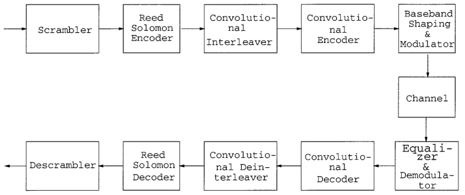
The block diagram of the DVB satellite (DVB-S) system [3] is shown in Fig. 1, which is composed of an MPEG-2 video encoder (not shown in the diagram), channel coding modules and a quadrature phase shift keying (QPSK) modem [6]. The bitstream generated by the MPEG-2 encoder is packetized into frames of 188-bytes long. The video data in each packet is then randomized by the scrambler. The details concerning the scram-bler have not been included in this paper, since these may be obtained from the DVB-S standard [3].
Due to the poor error resilience of the MPEG-2 video codec, powerful concatenated channel coding is employed. The concatenated channel codec comprises a shortened Reed–Solomon (RS) outer code and an inner convolutional encoder. The 188-byte MPEG-2 video packet is extended by the Reed–Solomon encoder [4], [5] with parity information to facilitate error recovery to form a 204-byte packet. The Reed–Solomon decoder can then correct up to eight erroneous bytes for each 204-byte packet. Following this, the RS-coded packet is interleaved by a convolutional interleaver and further
Fig. 1. Schematic of the DVB satellite system.
TABLE I
PARAMETERS OF THE CC(n; k; K)
CONVOLUTIONALINNERENCODER OF THEDVB-S MODEM
TABLE II
[image:2.612.55.273.338.404.2]PARAMETERS OF THEINNERTURBOENCODERUSED TOREPLACE THEDVB-S SYSTEM’SCONVOLUTIONALCODER(RSC: RECURSIVESYSTEMATICCODE)
Fig. 2. Block diagram of turbo encoder.
protected by a half-rate inner convolutional encoder with a constraint length of 7 [4], [5].
Furthermore, the overall code rate of the concatenated coding scheme can be adapted by variable puncturing, not shown in the figure, which supports code rates of 1/2 (no puncturing) as well as 2/3, 3/4, 5/6, and 7/8. The parameters of the convolutional encoder are summarized in Table I.
In addition to implementing the standard DVB-S system as a benchmark, we have improved the system’s performance with the aid of a turbo codec [11], [12]. The block diagram of the turbo encoder is shown in Fig. 2. The turbo encoder is con-structed of two component encoders. Each component encoder is a half-rate convolutional encoder, whose parameters are listed in Table II. The two component encoders are used to encode the same input bits, although the input bits of the second compo-nent encoder are interleaved before encoding. The output bits of the two component codes are punctured and multiplexed, in order to form a single output bitstream. The component encoder used here is known as a half-rate recursive systematic convolu-tional encoder (RSC) [13]. It generates one parity bit and one systematic output bit for every input bit. In order to provide an overall coding rate of one half, half the output bits from the two encoders must be punctured. The puncturing arrangement used in our work is to transmit all the systematic bits from the first encoder and every other parity bit from both encoders.
Readers interested in further details of the DVB-S system are referred to the DVB-S standard [3]. The performance of the standard DVB-S system and that of the turbo coded system is characterized in Section V. Let us now briefly consider the mul-tipath channel model used in our investigations.
III. CHANNELMODEL
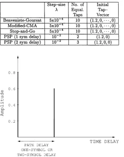
[image:2.612.41.290.465.738.2]TABLE III
SUMMARY OF THEEQUALIZERPARAMETERS USED IN THESIMULATIONS. THE
TAP-VECTOR(1:2; 0; 1 1 1 ; 0) INDICATES THAT THEFIRSTEQUALIZER
[image:3.612.295.548.57.450.2]COEFFICIENT ISINITIALIZED TO THEVALUE1.2, WHILE THEOTHERS TO0
Fig. 3. Two-path satellite channel model with either a one-symbol or two-symbol delay.
past 20 years, various researchers have concentrated their efforts on attempting to model the satellite channel, typically within a land mobile satellite channel scenario. However, the majority of the work conducted for example by Vogel and his colleagues [17]–[20], concentrated on modeling the statistical properties of a narrowband satellite channel in lower frequency bands, such as the 870 MHz UHF band and the 1.5 GHz L-band.
However, our high bitrate DVB satellite system requires a high bandwidth, hence the video bitstream is exposed to disper-sive wideband propagation conditions. Recently, Saunders et al. [21], [22] have proposed the employment of multipath channel models to study the satellite channel, although their study was concentrated on the L-band and S-band only.
Due to the dearth of reported work on wideband satellite channel modeling in the K-band, we have adopted a simpler approach. The channel model employed in this study was the two-path -symbol spaced impulse response, where is the symbol-duration. In our studies we used and . This corresponds to a stationary dispersive transmission channel. Our channel model assumed that the receiver had a direct line-of-sight with the satellite as well as a second path caused by a single reflector probably from a nearby building or due to ground re-flection. The ground reflection may be strong, if the satellite receiver dish is only tilted at a low angle.
(a)
(b)
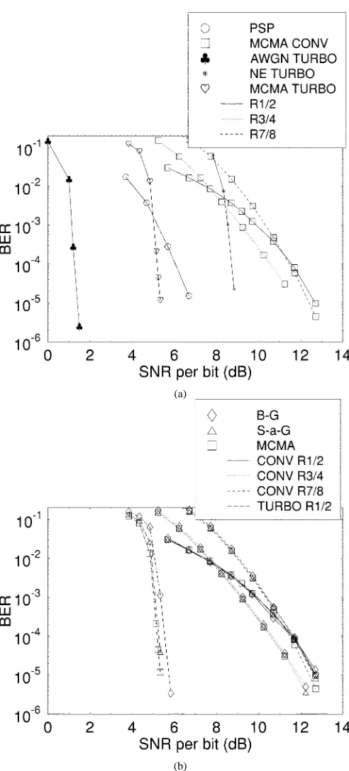
[image:3.612.42.552.64.448.2]Fig. 4. Average BER versus SNR per bit performance after equalization and demodulation employing QPSK modulation and one-symbol delay channel (NE: Non-Equalized; MCMA: Modified Constant Modulus Algorithm). (a) After equalization and demodulation; (b) Same as (a) but enlarged in order to show performance difference of the blind equalizer, when different convolutional code rates are used.
[image:3.612.42.296.106.426.2](a)
[image:4.612.42.288.54.598.2](b)
Fig. 6. Average BER versus SNR per bit performance after convolutional or turbo decoding for QPSK modulation and one-symbol delay channel (NE: Non-Equalized; B–G: Benveniste–Goursat; S-a-G: Stop-and-Go; MCMA: Modified Constant Modulus Algorithm; PSP: Per-Survivor-Processing). (a) PSP and linear equalizers; (b) Linear equalizers only.
Based on these channel models, we studied the ability of a range of blind equalizer algorithms to converge under various path delay conditions. In the next section we provide a brief overview of the various blind equalizers employed in our ex-periments, noting that the readers who are mainly interested in the system’s performance may proceed directly to our perfor-mance analysis section, namely to Section V.
IV. THEBLINDEQUALIZERS
In this section the blind equalizers used in the system are presented. The following blind equalizers have been studied:
• The Modified Constant Modulus Algorithm (MCMA) [23]
• The Benveniste–Goursat Algorithm (B–G) [24] • The Stop-and-Go Algorithm (S-a-G)[25]
• The Per-Survivor Processing (PSP) Algorithm [26]. We will now briefly introduce these algorithms. First we de-fine the variables that we will use:
(1)
(2)
(3)
where is the received symbol vector at time , containing the most recent received symbols, while , are the number of equalizer feedback and feedforward taps, respec-tively. Furthermore, is the equalizer tap-vector, consisting of the equalizer tap values and is the equalized symbol at time , given by the convolution of the received signal with the equalizers impulse response, while stands for matrix trans-pose. Note that the variables of (1)–(3) assume complex values, when multi-level modulation is employed.
The Modified CMA (MCMA) is an improved version of Go-dard’s well-known Constant Modulus Algorithm (CMA) [27]. The philosophy of the CMA is based on forcing the magni-tude of the equalized signal to a constant value. In mathematical terms the CMA is based on minimizing the cost function:
(4)
where is a suitably chosen constant and stands for the expectation. Similarly to the CMA, the MCMA, which was pro-posed by Wesolowsky [23], forces the real and imaginary parts of the complex signal to the constant values of and , respectively, according to the equalizer tap update equation of [23]:
Re Re
Im Im (5)
where is the step-size parameter and the , constant parameters of the algorithm are defined as:
Re
Re (6)
Im
(a)
[image:5.612.296.549.56.329.2](b)
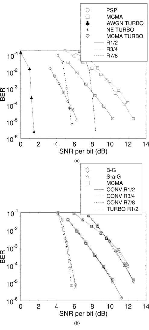
Fig. 7. Average BER versus SNR per bit after equalization and demodulation for 16-QAM over the one-symbol delay two-path channel of Fig. 3 (MCMA: Modified Constant Modulus Algorithm). (a) After equalization and demodulation; (b) Same as (a) but enlarged in order to show performance difference of the blind equalizer, when different convolutional code rates are used.
where is the transmitted signal at time instant .
The Benveniste–Goursat (B–G) algorithm [24] is an amalgam of the Sato’s algorithm [28] and the decision-directed (DD) algorithm [6]. Strictly speaking, the decision-directed algorithm is not a blind equalization technique, since its convergence is highly dependent on the channel.
This algorithm estimates the error between the equalized signal and the detected signal as:
(8)
where is the receiver’s estimate of the transmitted signal at time instant . Similarly to the DD algorithm’s error term, the Sato-type error [28] is defined as:
[image:5.612.44.306.59.450.2](9)
Fig. 8. Average BER versus SNR per bit after Viterbi or turbo decoding for 16-QAM over the one-symbol delay two-path channel of Fig. 3 (B–G: Benveniste–Goursat; S-a-G: Stop-and-Go; MCMA: Modified Constant Modulus Algorithm; PSP: Per-Survivor-Processing).
where is a constant parameter of the Sato-algorithm, defined as:
Re Re
Im
Im (10)
and sign Re sign Im is the complex
sign function. The B–G algorithm combines the above two error terms into one:
(11)
where the two error terms are suitably weighted by the constant parameters and in (11). Using this error term, the B–G equalizer updates the equalizer coefficients according to the fol-lowing equalizer tap update equations [24]:
(12)
In our investigations, the weights were chosen as , , so that the Sato-error was weighted more heavily, than the DD-error.
The Stop-and-Go (S-a-G) algorithm [25] is a variant of the decision-directed algorithm [6], where at each equalizer coef-ficient adjustment iteration the update is enabled or disabled, depending on whether the update is likely to be correct. The up-date equations of this algorithm are given by [25]:
Re
Im (13)
(a)
[image:6.612.41.288.60.454.2](b)
Fig. 9. Average BER versus SNR per bit performance after equalization and demodulation for QPSK modulation over the two-symbol of Fig. 3 (B–G: Benveniste–Goursat). (a) After equalization and demodulation; (b) Same as (a) but enlarged in order to show performance difference of the blind equalizer, when different convolutional code rates are used.
enable or disable the update of the equalizer according to the following rule. If the sign of the Sato-error (the real or the imaginary part independently) is the same as the sign of the de-cision-directed error, then the update takes place, otherwise it does not.
In mathematical terms, this is equivalent to [25]:
if Re Re
if Re Re
(14)
if Im Im
if Im Im .
(15) For a blind equalizer, this condition provides us with a mea-sure of the probability of the coefficient update being correct.
The PSP algorithm [26] is based on employing convolu-tional coding and hence it is a trellis-based sequence estimation technique, in which the channel is not known “a priori.” Hence,
an iterative channel estimation technique is employed, in order to estimate the channel jointly with the modulation symbol. In this sense, an initial channel estimation is used and the estima-tion is updated at each new symbol’s arrival.
In our case the update was based on the Least Mean Squares
(LMS) estimates, according to the following channel-tap update
equations [26]:
(16)
where
is the estimated (for one surviving path) channel tap-vector at time instant ,
is the associated estimated transmitted symbol vector and is the actually received symbol at time instant .
Each of the surviving paths in the trellis carries not only its own signal estimation, but also its own channel estimation. Moreover, convolutional decoding can take place jointly with this channel and data estimation procedure, leading to improved Bit Error Rate (BER) performance. A summary of the various equalizers’ parameters is given in Table III.
Having described the components of our enhanced DVB-S system, let us now consider the overall system’s performance.
V. PERFORMANCE OF THEDVB-S SCHEME
In this section, the performance of the DVB-S system was evaluated by means of simulations. Two modulation types were used, namely the standard QPSK and the enhanced 16-QAM schemes [6]. The channel model of Fig. 3 was employed. The first channel model had a one-symbol second-path delay, while in the second one the path-delay corresponded to the period of two symbols. The average BER versus SNR per bit performance was evaluated after the equalization and demodulation process, as well as after Viterbi [4] or turbo decoding [12]. The SNR per bit or is defined as follows:
SNR per bit (17)
where is the average received signal power, is the average received noise power and , which is dependent on the type of modulation scheme used and channel code rate (R), is defined as follows:
R Bits per modulation symbol (18)
(a)
[image:7.612.40.287.57.601.2](b)
Fig. 10. Average BER versus SNR per bit performance after convolutional or turbo decoding for QPSK modulation over the two-symbol delay two-path channel of Fig. 3 (B–G: Benveniste–Goursat; S-a-G: Stop-and-Go; MCMA: Modified Constant Modulus Algorithm; PSP: Per-Survivor-Processing). (a) PSP and linear equalizers; (b) Linear equalizers only.
A. Transmission Over the Symbol-Spaced Two-Path Channel
The linear equalizers’ performance was quantified and compared using QPSK modulation over the one-symbol delay two-path channel model of Fig. 4. Since all the equalizers’ BER performance was similar, only the Modified CMA results are shown in the figure.
The equalized performance over the one symbol-spaced channel was inferior to that over the nondispersive AWGN channel. However, as expected, it was better than without any equalization. Another observation for Fig. 4 was that the different punctured channel coding rates appeared to give slightly different bit error rates after equalization. This was because the linear blind equalizers required uncorrelated input bits in order to converge. However, the input bits were not entirely random, when convolutional coding was used. The consequences of violating the zero-correlation constraint are not generally known. Nevertheless, two potential problems were apparent. First, the equalizer may diverge from the desired equalizer equilibrium [29]. Secondly, the performance of the equalizer is expected to degrade, owing to the violation of the randomness requirement, which is imposed on the input bits in order to ensure that the blind equalizers will converge.
Since the channel used in our investigations was static, the first problem was not encountered. Instead, the second problem was what we actually observed. Fig. 5 quantifies the equal-izers’ performance degradation due to convolutional coding. We can observe a 0.1 dB SNR degradation, when the convolutional codec creates correlation among the bits for this specific case.
The average BER curves after Viterbi or turbo decoding are shown in Fig. 6(a). In this figure, the average BER over the nondispersive AWGN channel after turbo decoding constitutes the best case performance, while the average BER of the one-symbol delay two-path MCMA-equalized rate 7/8 convolution-ally coded scenario exhibits the worst case performance. Again, in this figure only the Modified-CMA was featured for sim-plicity. The performance of the remaining equalizers was char-acterized in Fig. 6(b). Clearly, the performance of all the linear equalizers investigated was similar.
It is observed in Fig. 6(a) that the combination of the Modified CMA blind equalizer with turbo decoding exhib-ited the best SNR performance over the one-symbol delay two-path channel. The only comparable alternative was the PSP algorithm. Although the performance of the PSP algorithm was better at low SNR’s, the associated curves cross over and the PSP algorithm’s performance became inferior below the average BER of . Although not shown in Fig. 6, the Reed–Solomon decoder, which was concatenated to either the convolutional or the turbo decoder, became effective, when the average BER of its input was below approximately . In this case, the PSP algorithm performed by at least 1 dB worse in the area of interest, which is at an average BER of .
A final observation in the context of Fig. 6(a) is that when convolutional decoding was used, the associated per-formance of the rate 1/2 convolutional coded scheme appeared slightly inferior to that of the rate 3/4 and the rate 7/8 scenarios beyond certain values. This was deemed to be a con-sequence of the fact that the 1/2-rate encoder introduced more correlation into the bitstream than its higher rate counterparts and this degraded the performance of the blind channel equal-izers, which performed best, when fed with random bits.
(a)
[image:8.612.43.290.47.547.2](b)
Fig. 11. Average BER versus SNR per bit performance (a) after equalization and demodulation and (b) after Viterbi or turbo decoding for 16-QAM over the two-symbol delay two-path channel of Fig. 3 (B–G: Benveniste–Goursat; S-a-G: Stop-and-Go; MCMA: Modified Constant Modulus Algorithm; PSP: Per-Survivor-Processing). (a) After equalization and demodulation; (b) After viterbi or turbo decoding.
Again, for simplicity, only the Modified CMA results are given. In this case the ranking order of the different coding rates fol-lowed our expectations more closely in the sense that the lowest coding rate of 1/2 was the best performer, followed by rate 3/4 codec, in turn followed by the least powerful rate 7/8 codec.
The Stop-and-Go algorithm has been excluded from these re-sults, since it does not converge for high SNR values. This hap-pens, because the equalization procedure is only activated, when there is a high probability of correct decision-directed equal-izer update. In our case, the equalequal-izer is initialized far from its convergence point and hence the decision-directed updates
Fig. 12. Learning curves for 16-QAM, one-symbol delay two-path channel at SNR= 18 dB.
are unlikely to be correct. In the absence of noise this leads to the update algorithm being permanently de-activated. If noise is present though, then some random perturbations from the point of the equalizers initialization can activate the Stop-and-Go al-gorithm and can lead to convergence. We made this observation at medium SNR values in our simulation study. For high SNR values though, the algorithm did not converge.
It is also interesting to compare the performance of the system for the QPSK and 16-QAM schemes. When the one-symbol delay two-path channel model of Fig. 3 was considered, the system was capable of supporting the use of 16-QAM with the provision of an additional SNR per bit of approximately 4–5 dB. This observation was made by comparing the performance of the DVB system when employing the Modified CMA and the half-rate convolutional or turbo code in Figs. 6 and 8 at a BER of . Although the original DVB-Satellite system only employs QPSK modulation, our simulations had shown that 16-QAM can be employed equally well for the range of blind equalizers that we have used in our work. This allowed us to double the video bitrate and hence to substantially improve the video quality. The comparison of Figs. 6 and 8 also reveals the extra SNR requirement of approximately 4–5 dB of 16QAM over QPSK can be eliminated by employing turbo coding at the cost of a higher implementational complexity. This allowed us to accommodate a doubled bitrate within a given bandwidth, which improved the video quality.
B. Transmission Over the Two-Symbol Delay Two-Path Channel
In Figs. 9 (only for the Benveniste–Goursat algorithm for simplicity) and 10 the corresponding BER results for the two-symbol delay two-path channel of Fig. 3 are given for QPSK. The associated trends are similar to those in Figs. 4 and 6, al-though some differences can be observed, as listed below:
[image:8.612.305.548.62.254.2]which is in the range, where the RS decoder guarantees an extremely low probability of error.
• The rate 1/2 convolutional decoding was now the best per-former, when convolutional decoding is concerned, while the rate 3/4 scheme exhibited the worst performance. Finally, in Fig. 11, the associated 16-QAM results are pre-sented. Notice that the Stop-and-Go algorithm was again ex-cluded from the results. Furthermore, we observe a high per-formance difference between the Benveniste–Goursat algorithm and the Modified CMA. In the previous cases we did not ob-serve such a significant difference. The difference in this case is that the channel exhibits an increased delay spread. This illus-trated the capability of the equalizers to cope with more wide-spread multipaths, while keeping the equalizer order constant at 10. The Benveniste–Goursat equalizer was more efficient, than the Modified CMA in this case.
It is interesting to note that in this case, the performance of the different coding rates was again in the expected order, the rate 1/2 being the best, followed by the rate 3/4 and then the rate 7/8 scheme.
If we compare the performance of the system employing QPSK and 16-QAM over the two-symbol delay two-path channel of Fig. 3, we again observe that 16-QAM can be incorporated into the DVB system, if an extra 5 dB of SNR per bit is affordable in power budget terms. However, only the B–G algorithm is worthwhile considering here out of the three linear equalizers of Table III.This observation was made by comparing the performance of the DVB system when employing the Benveniste–Goursat equalizer and the half-rate convolutional coder in Figs. 10 and 11.
[image:9.612.320.535.118.197.2]C. Performance Summary of the DVB-S System
Table IV provides an approximation of the convergence speed of each blind equalization algorithm of Table III. It is clear that PSP exhibited the fastest convergence, followed by the Ben-veniste–Goursat algorithm. In our simulations the convergence was quantified by observing the slope of the BER curve, and finding when this curve was reaching the associated residual BER, implying that the BER has reached its steady-state value. Fig. 12 gives an illustrative example of the equalizers conver-gence for 16-QAM. The Stop-and-Go algorithm converges sig-nificantly slower than the other algorithms, which can also be seen from Table IV. This happens because, during the startup, the algorithm is de-activated most of the time, an effect which becomes more severe with an increasing QAM order.
Fig. 13 portrays the corresponding reconstructed video quality in terms of the average peak signal-to-noise ratio (PSNR) versus channel SNR (CSNR) for the one-symbol delay and two-symbol delay two-path channel model of Fig. 3. The PSNR is defined as follows:
PSNR (19)
TABLE IV
EQUALIZERCONVERGENCESPEED(INMILLISECONDS) MEASURED IN THE
SIMULATIONS, GIVEN AS ANESTIMATE OFTIMEREQUIRED FORCONVERGENCE WHEN1/2 RATEPUNCTURING IS USED(x sym: x-SYMBOLDELAYTWO-PATH
CHANNEL ANDxCANTAKEEITHER THEVALUE1OR2)
TABLE V
SUMMARY OFPERFORMANCERESULTSOVER THEDISPERSIVEONE-SYMBOL
DELAYTWO-PATHAWGN CHANNEL OFFIG. 3 TOLERATING APSNR DEGRADATION OF2 dB
TABLE VI
SUMMARY OFPERFORMANCERESULTSOVER THEDISPERSIVETWO-SYMBOL
DELAYTWO-PATHAWGN CHANNEL OFFIG. 3 TOLERATING APSNR DEGRADATION OF2 dB
where is the difference between the uncoded pixel value and the reconstructed pixel value. The variables and refer to the dimension of the image. The maximum possible 8-bit rep-resented pixel luminance value of 255 was used in (19) in order to mitigate the PSNR’s dependence on the video material used. The average PSNR is then the mean of the PSNR values com-puted for all the images constituting the video sequence.
[image:9.612.305.546.237.388.2](a)
[image:10.612.332.524.483.552.2](b)
Fig. 13. Average PSNR versus channel SNR for: (a) the one-symbol delay two-path channel model, and (b) the two-symbol delay two-path channel model of Fig. 3 at a video bitrate of 2.5 Mbit/s using the “Football” sequence. (a) One-symbol delay two-path channel model; (b) Two-symbol delay two-path channel model.
Tables VII and VIII provide a summary of the SNR per bit required for the various system configurations. The BER threshold of was selected here, since at this average BER after Viterbi or turbo decoding, the RS decoder becomes effective, guaranteeing near error-free performance. This also translates into near unimpaired reconstructed video quality.
Finally, in Table IX the QAM symbol rate or Baud rate is given for different puncturing rates and for different modulation schemes, based on the requirement of supporting a video bit rate of 2.5 Mbit/sec. We observe that the Baud rate is between 0.779 and 2.73 MBd, depending on the coding rate and the number of bits per modulation symbol.
VI. CONCLUSIONS ANDFUTUREWORK
In this contribution, we have investigated the performance of a turbo-coded DVB system in a satellite broadcast environment. A range of system performance results was presented based on the standard DVB-S scheme, as well as on a turbo-coded scheme in conjunction with blind-equalized QPSK/16QAM. The con-volutional code specified in the standard system was substituted
TABLE VII
SUMMARY OFSYSTEMPERFORMANCERESULTSOVER THEDISPERSIVE
ONE-SYMBOLDELAYTWO-PATHAWGN CHANNEL OFFIG. 3 TOLERATING AN
AVERAGEBEROF10 , WHICH WASEVALUATEDAFTERVITERBI OR
TURBODECODING BUTBEFORERS DECODING
TABLE VIII
SUMMARY OFSYSTEMPERFORMANCERESULTSOVER THEDISPERSIVE
ONE-SYMBOLDELAYTWO-PATHAWGN CHANNEL OFFIG. 3 TOLERATING AN
AVERAGEBEROF10 , WHICH WASEVALUATEDAFTERVITERBI OR
TURBODECODING BUTBEFORERS DECODING
TABLE IX
THECHANNELBITRATE FOR THETHREEDIFFERENTPUNCTUREDCODING
RATES AND FOR THETWOMODULATIONS
with turbo coding, which resulted in a substantial coding gain of approximately 4–5 dB. We have also shown that 16-QAM can be utilized instead of QPSK, if an extra 5 dB SNR per bit gain is added to the link budget. This extra transmitted power require-ment can be eliminated upon invoking the more complex turbo codec, which requires lower transmitted power for attaining the same performance as the standard convolutional codecs.
turbo coded is also of interest. A range of further wireless video communications issues are addressed in [30].
ACKNOWLEDGMENT
The authors would like to thank the reviewers for their con-structive critique.
REFERENCES
[1] ETSI, “Digital Video Broadcasting (DVB); Framing structure, channel coding and modulation for digital terrestrial television,”, EN 300 744 V1.1.2, August 1997.
[2] , “Digital Video Broadcasting (DVB); Framing structure, channel coding and modulation for cable systems,”, EN 300 429 V1.2.1, De-cember 1997.
[3] , “Digital Video Broadcasting (DVB); Framing structure, channel coding and modulation for 11/12 GHz Satellite Services,”, EN 300 421 V1.1.2, August 1997.
[4] R. Steele and L. Hanzo, Eds., Mobile Radio Communications, 2 ed: John Wiley & Sons/IEEE Press, 1999.
[5] A. M. Michelson and A. H. Levesque, Error Control Techniques for Digital Communication: Wiley-Interscience, 1985.
[6] L. Hanzo, W. T. Webb, and T. Keller, Single and Multicarrier Quadra-ture Amplitude Modulation: John Wiley & Sons/IEEE Press, 1999. [7] G. Reali, G. Baruffa, S. Cacopardi, and F. Frescura, “Enhancing satellite
broadcasting services using multiresolution modulations,” IEEE Trans-actions on Broadcasting, vol. 44, pp. 497–506, December 1998. [8] Y. F. Hsu, Y. C. Chen, C. J. Huang, and M. J. Sun, “MPEG-2 spatial
scalable coding and transport stream error concealment for satellite TV broadcasting using Ka-band,” IEEE Transactions on Broadcasting, vol. 44, no. 1, pp. 77–86, March 1998.
[9] L. Atzori, F. G. B. De Natale, M. Di Gregario, and D. D. Giusto, “Multimedia information broadcasting using digital TV channels,” IEEE Transactions on Broadcasting, vol. 43, no. 4, pp. 383–392, December 1997.
[10] W. Sohn, O. H. Kwon, and J. S. Chae, “Digital DBS system design and implementation for TV and data broadcasting using Koreasat,” IEEE Transactions on Broadcasting, vol. 44, no. 3, pp. 316–323, September 1998.
[11] C. Berrou, A. Glavieux, and P. Thitimajshima, “Near Shannon limit error-correcting coding and decoding: turbo codes,” in IEEE Proceed-ings of the International Conference on Communications, Geneva, Switzerland, May 1993, pp. 1064–1070.
[12] C. Berrou and A. Glavieux, “Near optimum error correcting coding and decoding: turbo codes,” IEEE Transactions on Communications, vol. 44, no. 10, pp. 1261–1271, October 1996.
[13] S. B. Wicker, Error Control Systems for Digital Communication and Storage: Prentice Hall, 1994.
[14] P. Robertson, E. Villebrun, and P. Hoeher, “A comparison of optimal and suboptimal MAP decoding algorithms operating in the log domain,” in IEEE Proceedings of the International Conference on Communications, June 1995, pp. 1009–1013.
[15] J. Griffiths, Radio Wave Propagation and Antennas—An Introduction: Prentice Hall, 1987.
[16] M. S. Karaliopoulos and F.-N. Pavlidou, “Modeling the land mobile satellite channel: A review,” Electronics and Communication Engi-neering Journal, vol. 11, no. 5, pp. 235–248, 1999.
[17] J. Goldhirsh and W. J. Vogel, “Mobile satellite system fade statistics for shadowing and multipath from roadside trees at UHF and L-band,” IEEE Transactions on Antennas and Propagation, vol. 37, no. 4, pp. 489–498, April 1989.
[18] W. J. Vogel and J. Goldhirsh, “Multipath fading at L band for low ele-vation angle, land mobile satellite scenarios,” IEEE Journal on Selected Areas in Communications, vol. 13, no. 2, pp. 197–204, February 1995. [19] W. J. Vogel and G. W. Torrence, “Propagation measurements for satellite
radio reception inside buildings,” IEEE Transactions on Antennas and Propagation, vol. 41, no. 7, pp. 954–961, July 1993.
[20] W. J. Vogel and U. S. Hong, “Measurement and modeling of land mo-bile satellite propagation at UHF and L-band,” IEEE Transactions on Antennas and Propagation, vol. 36, no. 5, pp. 707–719, May 1988. [21] S. R. Saunders, C. Tzaras, and B. G. Evans, “Physical Statistical
Prop-agation Model for Mobile Satellite Channel,” European Commission, Tech. Rep., 1998.
[22] S. Saunders, Antennas and Propagation for Wireless Communication Systems Concept and Design: John Wiley & Sons, 1999.
[23] K. Wesolowsky, “Analysis and properties of the modified constant modulus algorithm for blind equalization,” European Transactions on Telecommunication, vol. 3, no. 3, pp. 225–230, May/June 1992. [24] M. Goursat and A. Benveniste, “Blind equalizers,” IEEE Transactions
on Communications, vol. COM–28, no. 11, pp. 871–883, August 1984. [25] G. Picchi and G. Prati, “Blind equalization and carrier recovery using a “stop-and-go” decision-directed algorithm,” IEEE Transactions on Communications, vol. COM–35, no. 9, pp. 877–887, September 1987. [26] A. Polydoros, R. Raheli, and C. Tzou, “Per-survivor processing:
A general approach to MLSE in uncertain environments,” IEEE Transactions on Communications, vol. COM–43, no. 2-4, pp. 354–364, February/April 1995.
[27] D. N. Godard, “Self-recovering equalization and carrier tracking in two-dimensional data communication systems,” IEEE Transactions on Com-munications, vol. COM–28, no. 11, pp. 1867–1875, November 1980. [28] Y. Sato, “A method of self-recovering equalization for multilevel
ampli-tude-modulation systems,” IEEE Transactions on Communications, vol. COM-23, pp. 679–682, June 1975.
[29] Z. Ding, R. A. Kennedy, B. D. O. Anderson, and R. C. Johnson, “Ill-convergence of Godard blind equalizers in data communications sys-tems,” IEEE Transactions on Communications, vol. COM–39, no. 9, pp. 1313–1327, September 1991.
[30] L. Hanzo, P. J. Cherriman, and J. Streit, Modern Video Compression and Communications: Principles and Applications for Fixed and Wireless Channels: IEEE Press, 1998, to be published.
Chee-Siong Lee received a first class honors degree in electrical engineering at the University of Southampton in 1997. Since then, he has been with the Wireless Multimedia Communications Group at the University of Southampton, working toward the Ph.D. degree in mobile multimedia communications. His current areas of interest include video compres-sion and various aspects of communications.
Spyros Vlahoyiannatos studied electrical and computer engineering at the National Technical University of Athens and graduated in 1997. He is currently working toward the Ph.D. degree in the Wireless Multimedia Communications Group at the University of Southampton. His area of research is the blind equalization of mobile fading channels.