2540·M·500
MODEL 2540
PERFORATED TAPE READER
OPERATION AND MAINTENANCE MANUAL
DIG I T RON I C
s®
COR P 0 RAT ION
Albertson, Long Island, New York Tel: (516) 484-1000
®
COPYRIGHT
©
1971 BY DIGITRONICS CORPORATION. PRINTED IN THE UNITED STATES OF AMERICA. ALL RIGHTS RESERVED. THIS BOOK OR PARTS THEREOF MAY NOT BE REPRODUCED IN ANY FORM WITHOUT PERMISSION OF THE PUBLISHERS.Address comments regarding this publication to Digitronics Publication Dept., Albertson, L. I., N. Y. 11507
Paragraph 1.1 1.2 1.3 1.4 1. 4.1 1. 4. 2 1. 4.2. 1 1. 4. 2.2 1. 4.2.3 1.5 1. 5. 1 1. 5.2 1. 5.2.1 1.5.2.2 1. 5.2. 3 1. 5.2. 4 1. 5.3 1. 5. 3. 1 1. 5.3.2 1. 5. 3. 3 1. 5.3.4 1. 5.4 1. 5.4.1 1. 5.4.2 1. 5.4.3 1. 5.4.4 1.6 1.7 1. 7.1 1. 7.2 1. 7. 3 1.8 1.9 2.1 2.2 2.3 2.4 2.4.1 2.4. 1. 1 2.4. 1. 2
2540-M-500
TABLE OF CONTENTS
SECTION I INTRODUCTION General . . . .
Model Descriptions. Applications . Basic Unit. . Specifications
Interface Requirements .
Pinch Roller and Brake Solenoids Exciter Lamp
Readhead . . . Electronics Unit Specifications .
Circuit Characteristics. Data Channels . . . . Sprocket Channel. . . .
Pinch Roller and Brake Circuits. Lamp Voltage Regulator. . . . . Electronics Unit Interface Requirements Data Outputs. .
Sprocket Output Tape Control. .
Operating Voltage Requirements . Data Gating Facilities.
Data Control Common. C12345 . . . . . C6, C7, C8 . . . Sprocket Control . Power Supply . Manual Controls Power Switch . Tape Width Selector Tape Load Lever. . Options . . . . Compatible Tape Handlers.
SECTION II INSTALLATION General. . . .
Unpacking . . . . Mechanical Installation Electrical Installation. Mating Connector Wiring Models 2540T and B2540T.
Models 2540E, B2540E, 2540EP, B2540EP
ii
Paragraph 2.4.2 2.5 2.5.1 2.5.2
3.1 3.2 3.3 3.3.1 3.3.2
4. 1 4.2 4.3 4.3.1 4.3.2 4.4
4.4.1 4.4.1.1 4.4. 1. 2 4.4.2 4.4.3 4.4.4
5.1 5.2 5.2.1 5.2.2 5.2.3 5.2.4 5.3 5.4 5.4.1 5.4.2 5.4.3 5.4.4 5.4.5 5.4.6 5.4.7
2540-M-500
TABLE OF CONTENTS (Cont'd.l
SECTION II INSTALLATION (Cont'd.) AC Power . . .
Initial Installation Checks . Voltage Checks. . . Performance Checks
SECTION III OPERATING PROCEDURES General . . . .
Operating Controls. . Operating Procedures. Loading Tape
Tape Read . .
SECTION IV THEORY OF OPERATION General . . . .
Logic Symbols . Functional Description Basic Unit . . . Electronics Unit Circuit Description.
Basic Unit, Detailed Analysis Tape Drive System . . . Tape Read System . . . . . Electronics Unit, Detailed Analysis Power Supply, Detailed Analysis. . End- of- Tape Sensor, Detailed Analysis.
SECTION V MAINTENANCE General . . . .
Preventi ve Maintenance. Periodic Inspection. . .
Periodic Component Replacement Lubrication
Cleaning . . . . Correcti ve Maintenance.
Component Removal Procedures . Exciter Lamp . . . .
Drive Belt. . . . Pinch Roller Solenoid. Brake Coil. . . . Capstan Assembly . . Drive Motor Assembly Readhead Assembly. .
2540-M-500
2-1 2-1 2-1 2-3
3-1 3-1 3-1 3-1 3-1
4-1 4-1 4-1 4-1 4-3 4-4 4-4
4-4 4-4
4-4 4-5/6 4-5/6
5-1 5-1 5-1 5-1 5-1 5-1 5-1 5-1 5-4 5-4 5-4 5-5
5-7 5-7
Paragraph 5.5 5.5.1 5.5.2 5.5.3 5.5.4
6. 1
6.2 6.3 6.4 6.5
6.6
6.7
Table 1-1 1-2 1-3 1-4 1-5 1-6 1-7 2-1 2-2 3-1 4-1 5-1 5-2 5-3 5-4
2540-M-500
TABLE OF CONTENTS (Cont/d')
SECTION V MAINTENANCE (Cont'd.) Adjustment Procedures .
Exci te r Lamp . . . . Drive Belt Tension. . Pinch Roller Assembly Brake Assembly . . .
SECTION VI ILLUSTRATED PARTS BREAKDOWN General . . . .
Figure and Index Number Part Number . . . . Description . . . . Units Per Assembly Usable On Code Alternate Parts . .
SECTION VII REFERENCE DRA\V1NGS
APPENDIX A - WARRANTY
APPENDIX B - MANUFACTURING SPECITICA TIONS
APPENDIX C - TRANSISTOR AND DIODE SPECITICA TIONS
LIST OF TABLES
Model Descriptions. . . Basic Unit Specifications Electronics Unit Specifications. Model 2540 Series Options. Compatible Tape Handlers. Tape Handler Interface Wiring.
Alternate Tape Handler Interface Wiring Electronics Unit Interface.
Electronics Unit Voltage Measurements. Operating Controls .
Logic Symbols .
Periodic Inspection Schedule. Component Replacement Schedule Circuit Waveforms.
Trouble Isolation Guide.
2540-M-500
5-8
5-8 5-9 5-9 5-10
6-1/2 6-1/2 6-1/2 6-1/2 6-1/2 6-1/2 6-1/2
Page 1-1 1-3 1-6 1-9 1-10 1-10 1-10 2-3 2-3 3-1 4-1 5-3 5-3 5-4 5-6
iv Figure
1-1 1-2 1-3 1-4 1-5 1-6 1-7 1-8 1-9
2-1 2-2 3-1 3-2
4-1 4-2 5-1 5-2
5-3
5-4
5-5
5-6 5-7 5-8 6-1 6-1 6-2 6-3 6-4 6-5 6-6 6-7 6-8 6-9
7-1 7-2 7-3
2540-M-500
LIST OF ILLUSTRATIONS
Mode12540 . . . .
Recommended Solenoid Drive Circuit, Schematic Diagram Solenoid Current Waveforms. . . . Typical Preamplifier Circuit, Simplified Schematic . . . Relati ve Coincidence of Sprocket and Data Channel Outputs Recommended Sprocket and Data Channel Interface Wiring Channel Output Circuit, Simplified Schematic Diagram. . Tape Load and Rewind Control, Interface Wiring. . . . . Alternate Tape Load and Rewind Control, Interface Wiring . Outline Drawing . . . .
Interface Schematic Diagram, Basic Unit. Operating Controls. . . . .
Tape Path . . . .
Basic Unit, Functional Block Diagram Electronics Unit, Logic Diagram. Component Locations. . . . Solenoid Radial Gap Adjustment . Capstan Bearing Preload Adjustment . Exciter Lamp Vertical Positioning. . Drive Belt Tension Adjustment. . . . Pinch Roller/Capstan Centerline Adjustment Pinch Roller and Capstan Parallelism Brake Armature Positioning. . . . . Reader Panel Assembly (Sheet 1 of 2). Reader Panel Assembly (Sheet 2 of 2). PiIich Roller Assembly . . . . Brake Assembly . . . .. . . .
Photo Head Assembly, Standard 5- 8 Channel . Photo Head Assembly, Standard/Teletypesetter . Power Supply Assembly . . .
Printed Circuit Board Assembly . End of Tape Assembly . . . . . Connector Assembly . . . . Model (B)2540T, Schematic Diagram. Model (B)2540EP, Schematic Diagram . . End of Tape Sensor, Schematic Diagram.
2540-M-500
Page 1-1 1-2 1-2 1-5 1-5 1-7 1-8 1-8 1-8 2-2 2-4 3-1 3-2
2540-M-500 Section I, Introduction Par agrapl1s
1.TtIlrougnl.
4SECTION I
INTRODUCTION
1.1 GENERAL
The Digitronics Model 2540 Series Perforated Tape Reader (Figure 1-1) is designed to read 5-, 6- and 7 -, or 8-level perforated tape in the forward or re-verse direction at speeds to 600 characters per sec-ond. The Model 2540 combines a patented-design readhead with integrated circuit channel amplifiers and results in a modern, accurate, and reliable means for high-speed reading of perforated tape. The Model 2540 converts information punched on tape into dc signal levels which are fully compatible with inte-grated circuit logic.
This section describes the models of the 2540 series and outlines the applications, specifications, options, and systems requirements. In addition, a physical description of the unit and information on compatible tape handlers is provided.
1.2 MODEL DESCRIPTIONS
The basic Model 2540 is a unidirectional or bidirec-tional tape transport available on a 10- or 19-inch wide panel, to which one or both of the following sub-assemblies may be added:
a. Electronics Unit (unidirectional or bidirection-:-al): features integrated circuit channel amplifiers and discrete component drive circuits.
b. Power Supply: supplies all of the operating and drive voltages required by the basic reader and the electronics unit.
Figure 1-1. Model 2540
The model numbers for the different configurations of the 2540 Series Reader are given in Table 1-1.
1.3 APPLICATIONS
The Model 2540 Series Readers may be used in the assembly of digital computers or numerically con-trolled machine tools. The units can also be used with ground support equipment, high-speed printers, and other instrumentation systems.
1.4 BASIC UNIT
The basic unit includes the readhead assembly which consists of an exciter lamp, collimating le~s, and the readhead with built- in discrete component preamplifi-ers for the sprocket channel and the data channels. Standard 200,300,400, and 600 character-per-second unidirectional units have direct-drive capstans; other speeds have indirect-drive capstans. Bidirectional units have indirect-drive forward capstans at speeds
Table 1-1. Model Descriptions
MODEL
DESCRIPTION NUMBER
Unidirectional Unit
2540T Unidirectional tape transport; includes built-in readhead amplifiers
2540E Unidirectional tape transport with electronics; includes integrated circuit channel amplifiers and drive circuits
2540EP Unidirectional tape transport with electronics and power supply
Bidirectional Unit
B2540T Bidirectional tape transport; includes built-in readhead amplifiers
B2540E Bidirectional tape transport with electronics; includes integrated circuit channel amplifiers and drive circuits
B2540EP Bidirectional tape transport with electronics and power supply
Section I, Introduction
Paragraphs 1. 4.1 through 1. 5
2540-M- 500
to 600 characters per second, and direct-drive re-verse capstans. Bidirectional units are available with a reverse speed of 200, 300, 400, or 600 char-acters per second which is determined by the selec-ted forward speed.
1.4.1 Specifications
For the Model 2540 Series basic unit technical spec-ifications, refer to Table 1- 2.
1.4.2 Interface Requirements
External equipment interface requirements consist of a drive voltage and control signals for the pinch roller and brake solenoids to control tape movement, exciter lamp voltage, and readhead voltage.
The readhead input voltage and output signals are routed through a 12/24-pin printed circuit connector, and all other input signals and voltages are routed through a 22/44-pin printed circuit connector. Both interface connectors are supplied with hoods.
1. 4.2.1 Pinch Roller and Brake Solenoids. The pinch roller and brake solenoids require a drive voltage of +28 ± 4 volts. Control of tape movement requires that one side of each solenoid winding be connected to a drive circuit similar to the one shown in Figure 1-2. The pinch roller and brake solenoid current requirements are 1.0 ampere (holding) for both solenoids, with a 1. 8 ampere surge for the pinch roller solenoid, and 1. 4 ampere surge for the brake solenoid. (See Figure 1-3. )
1.4.2.2 Exciter Lamp. The exciter lamp is wired in series with a 15-ohm, 20-watt adjustable resistor (R1), and requires an input operating voltage of 24 ± 1. 2 volts dc nominal with a maximum vari-ation of 0.5%. The adjustable resistor is used to compensate for error in nominal voltage and lamp variation. Resistor R1 is adjusted to achieve a duty cycle of 60 to 80% on for the data channel outputs, and 35 to 45% on for the sprocket channel output while the reader is reading a fully punched test tape. With resistor R1 properly adjusted, the voltage a-cross the lamp should be 16 to 20 volts.
1. 4.2.3 Readhead. The built-in preamplifier circuits in the readhead require an operating voltage of +5 ± O. 5 volts at 60 milliamperes (total), with a maximum ripple of O. 1 volt. This voltage should be regulated to O. 1 volt (or 2%). The readhead outputs are at +5 volts (open cirCuit) for a hole condition, and between 0 and +0.5 volts at 1. 67 milliamperes maximum for a no- hole condition. During a hole condition, the readhead amplifiers pull to +5 volts through a 10, OOO-ohm resistor (Figure 1-4).
The readhead output duty cycles are 60 to 80% on, 40 to 20% off for the data outputs; 35 to 45% on, 65 to 55% off for the sprocket output.
The maximum variations to the relative coincidence
+5V +28V +28V
IK
r - - - l
1/2W
:
25il:
IN3666 CONTROL
INPUT A
I
I
I
I
CONTROL
L _ _ _
J
INPUT B
470ll. 100 ).If +
1/2W
50VT
-5V =
PARAMETERS TQ-PD3053 TQ-PD3055
@25·C (2N3053 Selected) (2N3055 Selected)
Pc IW 100W
Ie (max) 0.5 a 100
BVcb (min) 70v @ Ima 100v@. 5ma
BVees(min) GOy @ Ima 70v @ 5ma
BV eb (min) 5v @Ima 5v @ 5ma
leBO (max) 0.25ma @ Vee = 30v 10ma ~ Vee =30Y, T= 100·C
hFE (min) 80 @ Ice = 200ma 30@Iee=4C
Vee (max)
*
1.5v @ I ee =200ma 1.2v @, Iee=4a Vbe (max)*
1.2Y @ Iee= 200ma, Vee < 1.5v 1.0v@ Iee=40,Vee< 1.2Y*
@, SaturationFigure 1-2. Recommended Solenoid Drive Circuit, Schematic Diagram
*I(amp) @,2BV
1.0 _ _ _
0.5 I-I-t-t++-+-I-H-+t-t-+t-t++-+-I-H-+t-t-+t-t+t-H-H-+t-t-+t+--f
o 2 3 4 5 6 7 B
t (millisec)
- - PINCH ROLLER
- - BRAKE
*
:!: 15% (approx.)Figure 1-3. Solenoid Current Waveforms
of the sprocket and data channel outputs are - 5 to +10% between the sprocket and any data channel (Fig-ure 1- 5).
1.5 ELECTRONICS UNIT
The electronics unit provides: (1) the additional fea-tutes of sprocket and data channel amplifiers, and (2) solenoid drive circuits for the basic reader. The electronics unit attaches directly to a bracket assem-bly behind the reader panel, and consists of a single printed circuit board having integrated circuit sprock-et and data channel amplifiers. Discrsprock-ete solid-state
2540-M-500 Section I, Introduction Table 1-2
Table 1- 2. Basic Unit Specifications
Read Mode
2540T .
B2540T
Read Speeds (in characters/second; given at 60 Hz line frequency)*
GENERAL
Unidirectional.
Bidirectional.
Unidirectional. (direct drive)
. . . . 200, 300, 400, or 600
Unidirectional . . . 100 to 600. (indirect drive)
Bidirectional . Forward
100-200
150-300
200-400
300-600
Reverse
200
300
400
600
Asynchronous . . . On units with slew speed of 300 Characters/second or more; up to 150 Characters/second maximum (forward), or 75 Characters/second maximum (reverse).
Start Response . . . The start response (time to advance one characte~) for units with slew speeds of 300 Characters/second or more, USing 12% oiled, 0.0035' to 0.005 inch thick paper tape, is 10 milliseconds maximum.
Stop Response . . . At 600 characters/second, on data holes of stop character or in space following stop character (provided stop command is applied within 50 microseconds of leading edge of sprocket associated with stop character).
Type of Tape . . . Paper, paper-mylar, aluminized mylar, or solid mylar; . 0025 to . 005 inch thick with no adjustment to pinch roller. Tapes with up to 40 per cent transmissivity are acceptable without electrical adjustments.
Tape Width . . . A three-position, operator adjustable tape guide enables reading 11/16-to I-inch (5- to 8-channel) tapes interchange-ably. The tape guide is provided with a locking feature which prevents accidental moving of the guide.
Input Tape Form . Strip, reeled, fan-folded or loop with butt joints.
Tape Perforations According to EIA standards.
Tape Loading. . . . In-line.
Tape Leader Required 4 inches minimum.
*Speeds vary proportionally with line frequency.
Section I, Introduction 2540- M- 500 Table 1-2 (Cont'd.)
Table 1- 2. Basic Unit Specifications (Cont'd. )
READHEAD PREAMPLIFIER OUTPUTS
Hole . . . · Pulls to +5 volts through a 10, OOO-ohm resistor.
No Hole . . · 0
~~: ~
volts at 1.67 milliamperes maximum.Duty Cycle · Data Outputs: 60 to 80% on.
Sprocket Output: 35 to 45% on.
Coincidence. . . Sprocket center line occurs from - 5% to +10% of centerline of any data channel.
Readhead Circuits . . . .
POWER AND ENVIRONMENTAL
· +5 ± O. 5 volts at 60 milliamperes with 0.1 volt maximum ripple. Voltage must be regulated to 0.1 volt (2%).
Exciter lamp . . . 24 ± 1. 2 volts dc nominal at 1 ampere, with maximum variation of O. 5%.
Pinch Roller and Brake Solenoids .
Drive motor. . .
Power Dissipation .
Temperature
Operating .
Storage .
Humidity
Operating
Storage .
Underwriters Laboratories Specification
Front Panel Width . . . .
Front Panel Thickness:
19-inch panel.
10- inch panel. .
Front Panel Height
Mounting Holes. .
1-4
· . +28 ± 4 volts at 1. 8 amperes maximum.
· 117 ± 10 volts 48 to 62 Hz, single phase ac at 0.65 amperes.
· 150 watts maximum.
· 00 to 550
Centigrade.
· _ 55 0 to +65 0
Centigrade.
· 10 to 90%.
· 0 to 100% without condensation.
· Unit designed to meet Underwriters Laboratories specifica-tion.
PHYSICAL CHARACTERISTICS
· 19 inches or 10 inches. (10-inch panel for use with rack adapter).
· . i
inch.· 1/8 inch.
· 5
i
inches.· . Spaced to fit RETMA rack (19-inch panel and 10-inch panel with rack adapter).
2540-M-500 Section I, Introduction
Paragraphs 1. 5. 1 through 1. 5.2.3
Table 1-2. Basic Unit Specifications (Cont'd. )
PHYSICAL CHARACTERISTICS (Cont'd.)
Depth Behind Front Panel . . · 7 inches.
Protrusion From Front Panel · 2 3/4 inches.
Weight. . . . · 23 pounds net.
Rack Adapter:
Width . . · 19 inches.
Height.
Thickness
Weight . . .
To Photovoltaic Cell (Readheadl
lOOK
+5V
10K
OUTPUT
· 7 inches.
· 3/8 inch.
. . 5 pounds.
OUTPUT
HOLE Pulls towards
(Transistor +5V through
Off) 10K resistor
NO HOLE 0+.5 V ot
(Transistor -0
On) I.S7ma
Figure 1-4. Typical Preamplifier Circuit, Simplified Schematic
component solenoid drive circuits and an exciter lamp voltage regulator are also contained on the printed circuit board.
1.5.1 Specifications
For technical specifications of the electronics unit, refer to Table 1-3.
1.5.2 Circuit Characteristics
The sprocket and eight data channel circuits amplify and shape the readhead outputs, providing sprocket and data outputs that are fully compatible with inte-grated circuit logic.
1. 5.2.1 Data Channels. Each data output of the readhead is shaped by a Schmitt trigger cir cuit. The output of this circuit is applied to the interface con-nector for use by the external equipment. The output of the Schmitt trigger circuit in parallel with a 1000-ohm resistor tied to +5 volts, pulls toward +5 volts during a hole condition, and is at 0 volts during a no-hole condition. Connections are available at the in-terface connector for gating the data outputs internal-ly using the internal sprocket (SPKTA) or externalinternal-ly.
DATA CHANNEL 30% 70% 30%
I
.--1---,1
ISPROCKET CHANNEL _ _ _ 1,-15_0Ic-00 40% 1I-~5_01c_o_1 _ _ _
MAXIMUM CHANNEL
{
-5%
~
40% 120%1SPROCKET I
VARIATION I
+10% I 25%
I
40% 11-5_1
% _ _ _
Figure 1- 5. Relative Coincidence of Sprocket and Data Channel Outputs
The different gating choices are described in Para-graph 1.5.4.
1. 5. 2. 2 Sprocket Channel. The sprocket output of the readhead is applied to two Schmitt trigger circuits which shape the sprocket signal into a square wave, permitting (at user's discretion) the use of the sprock-et to gate the data outputs. The output of the first Schmitt trigger circuit is applied to the interface con-nector for use as an internal gating signal (SPKTA) and to the second Schmitt trigger circuit. The output of the second Schmitt trigger circuit, which is in par-allel with a 1000-ohm resistor tied to +5 volts, pulls toward +5 volts during a hole condition and is at 0 volts during a no-hole condition. Both sprocket out-puts (SPKTA and SPKTB) or, just the external sprock-et output (SPKTB) may be controlled (enabled or in-hibited) by the external equipment.
1. 5.2.3 Pinch Roller and Brake Circuits. The electronics unit contains two identical drive circuits; one for the brake solenoid and one for the pinch-roller solenoid. Bidirectional units have a third drive circuit for the reverse pinch roller solenoid. The pinch roller and brake solenoids are mutually exclusive under control of run (forward or reverse)
Section I, Introduction 2540-M-500 Table 1-3
Table 1-3. Electronics Unit Specifications
OUTPUTS
Hole. . . Pulls to +5 volts through 1000-ohm resistor in parallel with TTL output.
No Hole
Data Channel
Sprocket Channel
Output Duty Cycle.
o
~~: ~
volts at 5 milliampereso
~~: ~
volts at 15 milliamperes.Data Outputs: 60 to 80% on.
Sprocket Output: 35 to 45% on.
Output Signal Coincidence . . . Sprocket center line occurs from -5% to +10% of centerline of any data channel.
CONTROL SIGNAL REQUIREMENTS
Pinch Roller
F orwar d . . . nerglze; E . 5 +1. -1. 0 5 vo s. It
Reverse (Bidirectional Unit)
Brake . . . .
Logic Circuits , . . . .
Solenoid and Lamp Circuits
Power Dissipation
Temperature
Operating . .
Storage.
Humidity
Operating.
Storage . .
Weight . . .
1-6
Deenergize; 0
~~: ~
volts at 5 milliamperes,Same as forward pinch roller.
Same as pinch roller.
POWER AND ENVIRONMENTAL
+5 ± 0.25 volts at 150 milliamperes maximum with 0.1 volt maximum ripple and 0.2 volt maximum variation.
- 5 ± 1 volts at 20 milliamperes maximum.
28 ± 4 volts dc at 2. 8 amperes maximum. 25 watts maximum (card only).
00
to +550
Centigrade.
_ 55 0 to +65 0
Centigrade.
10 to 90%
o
to 100% without condensation.0.5 pound (card only).
2540-M-500 Section I, Introduction
and stop signal inputs from the external equipment. The solenoids are energized when +5 volts is applied to their respective input, and deenergized when the input is at 0 volts.
1. 5. 2.4 Lamp Voltage Regulator. The lamp volt-age regulator provides a regulated 24 volts dc to the exciter lamp.
1.5.3 Electronics Unit Interface Requirements
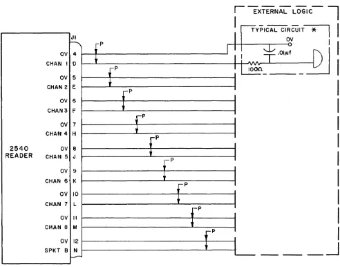
When the electronics unit is used, all input and out-put Signals and voltages are routed through a 25/50-pin printed circuit interface connector (J1). The wires interfacing the data and sprocket outputs with the external logic should each be twisted with another wire connected to 0 volts for the suppression of noise. If the Signal wires are one to ten feet long, it is recommended that an rc filtering network also be used. (See Figure 1- 6. )
1. 5. 3.1 Data Outputs. The data channel outputs
JI
h
fPOV 4
t
CHAN I D
fP OV 5
CHAN 2 E
t
r
P OV 6CHAN3 F
t
r
P OV 7+
CHAN 4 H
r
P
2540
ov
8READER
CHAN 5 J,
OV 9 CHAN 6 K
ov
10 CHAN 7 LOV II CHAN 8 M
ov
12 SPKT 8 Nl
-,-P
Paragraphs 1. 5. 2.4 through 1. 5.3.3
are derived from a TTL Schmitt trigger circuit (Figure 1-7). For a hole condition, the output is connected to +5 volts through a 1000-ohm resistor in parallel with the TTL output. For a no-hole condi-tion, the output is 0
~~.
4 volts at 5 milliamperes (maximum).1. 5.3.2 Sprocket Output. Two sprocket outputs are available at the interface connector (SPKTA and SPKTB). Sprocket Signal SPKTA is available as an internal gating signal. Sprocket Signal SPKTB is available for use by the external equipment and its outputs are the same as the data channels except that for a no-hole condition, the output circuit is capable of handling a maximum current for 15 milliamperes instead of 5 milliamperes.
1. 5. 3. 3 Tape Control. Control of tape movement requires the application of control signals to the brake drive circuit input (STOP) and each pinch roll-er drive circuit input (FWD and REV). The control
r - - - -
-I
TYPICAL CIRCUIT OVI
I.~
.01,..;
I
!
AAAI
loon
"""I
-
-I
IJ
I
I
J
I
I
I
I
II
I
-P I
I
I
r
P II
+
J
r
P I I+
1
I---
_---.l
[image:13.617.92.584.323.709.2]*
R C NETWORK USED WITH SIGNAL LEADS I -10 FT. LONG.Figure 1-6. Recommended Sprocket and Data Channel Interface Wiring
Section I, Introduction 2540-M-500 Paragraphs 1. 5.3.4 through 1. 5.4.3
+5V +5V
TTL
SCHMITT IK OUTPUT
TRIGGER CIRCUIT
OUTPUT HOLE (Transistor Off)
NO HOLE (Transistor On)
Pulls towards +5V through I K resistor
0+.4 V
-0 at
5mo*
I
I
II
*
15ma for sprocket channel [image:14.617.293.534.69.305.2]_ _ _ -=-_-1
Figure 1-7. Channel Output Circuit, Simplified Schematic Diagram
signal requirements are: energize, +5
~~
5 volts; deenergize, 0~~.
4 volts at 5milliampere~.
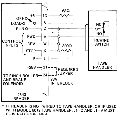
The in-put line to each drive circuit is gated with another input line (STOP CONTR, FWD CONTR, and REV CONTR) which is provided for additional control; e. g., tape load and rewind.Deenergization of the brake and pinch roller sole-noids for tape load and tape handler rewind can be provided by wiring the reader and interfacing it with the tape handler as shown in Figure 1-8 or, if per-mitted by the customer's application, wired as shown in Figure 1-9. When wired in this manner, the pinch roller and brake solenoids are inhibited, thereby preventing the solenoids from being energized when the reader Power switch is in the LOAD pOSition or when the tape handler is in the rewind mode.
1. 5.3.4 Operating Voltage Requirements. The electronics unit requires the following operating volt-age inputs:
a. +5 ± 0.25 volts at 150 milliamperes maxi-mum; ripple, 0.1 volt maximaxi-mum; variation, 0.2 maximum
b. - 5 ± 1 volts at 20 milliamperes maximum
c. 28 ± 4 volts dc at 2.8 amperes maximum
1.5.4 Data Gating Facilities
The different choices available (for gating of data) are described in the paragraphs which follow. Gating is accomplished by wiring sprocket Signal SPKTA to the appropriate pin of J1 (for internal gating with sprocket) or by an external signal. All gating lines are enabled when left floating.
1. 5.4.1 Data Control Common. The data control common line is used to gate all eight data channels.
OFF
RUN
{ FWD
CONTROL REV INPUTS
STOP
-5
+28V
TO PINCH ROLLER AND BRAKE SOLENOID
2540 READER
J1
68n 13
B C
V
REWIND
W SWITCH
X
U
TAPE 21 -.., REQUIRED HANDLER
_J
JUMPER 28V INTERLOCK* IF READER IS NOT WIRED TO TAPE HANDLER, OR IF USED WITH MODEL 6012 TAPE HANDLER, J1-C AND J1-V MUST BE WIRED TOGETHER.
Figure 1-8. Tape Load and Rewind Control Interface Wiring
The external gating signal requirements are: inhibit,
o
.~~.
4 volts at 15 milliamperes; enable, 5~~.
5 volts.1. 5.4.2 C12345. The C12345 gating line is used to gate data channels 1 through 5. The external
t · . I . t ·nh·b·t 0 +0.4 It ga Ing SIgna reqUlremen s are: I I I , 0 vo s
+0
-at 9.3 milliamperes; enable, 5 -1. 5 volts.
1. 5.4.3 C6, C7, C8. The C6, C7, and C8 gating lines are used for gating data channels 6, 7, and 8 individually. The external gating signal requirements
TO PINCH ROLLER AND BRAKE SOLENOID
2540 READER J1
REWIND SWITCH
TAPE HANDLER
* IF READER IS NOT WIRED TO TAPE HANDLER, OR IF USED WITH MODEL 6012 TAPE HANDLER, Jl - C AND Jl - 24 MUST BE WI RED TOGETHER.
Figure 1-9. Alternate Tape Load and Rewind Control, Interface Wiring
[image:14.617.36.269.82.320.2]2540-M-500 Section I, Introduction Paragraphs 1. 6 through 1. 8
are: inhibit, 0
~~.
4 volts at 1. 9 milliamperes, enable;o
+5 -1. 5 vo lts.
1. 5.4.4 Sprocket Control. Two lines (CSA and CSB) are available at the interface connector for ex-ternal control of sprocket. Both sprocket outputs (SPKTA and SPKTB) are controlled by CSA and sprocket output SPKTB only is controlled by CSB.
h I · I . t ·nh·b·t 0 +0.4
T e contro sIgna reqUlremen s are: I I I, -0
+0
volts at 1. 9 milliamperes; enable, 5 -1. 5 volts. The sprocket outputs are enabled when CSA and CSB are left floating.
1.6 POWER SUPPLY
The power supply is a self-contained assembly that mounts to the rear of the reader panel or rack adapter. It provides all of the operating and drive voltages required by the basic reader and the elec-tronics unit. The primary of the power supply transformer contains a dual winding which is wired for operation with either 115 or 230 volts ac, 48- 62 Hz. When the power supply is used, the 19-inch reader or rack adapter (with 10-inch panel) is re-quired. The specifications of the power supply are:
Power Requirements. . . 117 or 230 volts ± 10%,
Power Dissipation. Weight . .
1.7 MANUAL CONTROLS
1.7.1 Power Switch
48- 62 Hz. single phase ac.
135 watts maximum. 7.5 pounds.
Three-position (OFF, LOAD, RUN)_ two-pole toggle switch. Section A contacts, closed in RUN position only, may be used to deenergize pinch roll-er and brake solenoids for loading tape. Section B contacts apply ac power to drive motor when switch is in LOAD or RUN position.
1.7.2 Tape Width Selector
Adjustable tape guide mechanism allows reading 11/16-, 7/8-, or 1-inch tapes. A locking feature prevents accidental moving of the tape guide control. 1.7.3 Tape Load Lever
Disengages front tape guides to allow insertion and removal of tape.
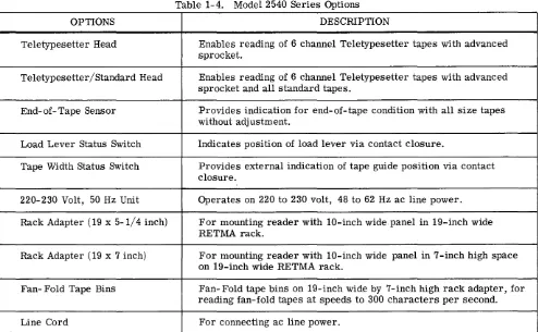
1.8 OPTIONS
[image:15.613.77.571.408.713.2]The options for the Model 2540 Series are listed in Table 1-4.
Table 1-4. Model 2540 Series Options
OPTIONS DESCRIPTION
Teletypesetter Head Enables reading of 6 channel Teletypesetter tapes with advanced sprocket.
Teletypesetter/Standard Head Enables reading of 6 channel Teletypesetter tapes with advanced sprocket and all standard tapes.
End-of-Tape Sensor Provides indication for end-of-tape condition with all size tapes without adjustment.
Load Lever Status Switch Indicates position of load lever via contact closure.
Tape Width Status Switch Provides external indication of tape guide position via contact closure.
220-230 Volt, 50 Hz Unit Operates on 220 to 230 volt, 48 to 62 Hz ac line power.
Rack Adapter (19 x 5-1/4 inch) For mounting reader with 10-inch wide panel in 19-inch wide RETMA rack.
Rack Adapter (19 x 7 inch) For mounting reader with 10-inch wide panel in 7 - inch high space on 19-inch wide RETMA rack.
Fan- Fold Tape Bins Fan- Fold tape bins on 19-inch wide by 7-inch high rack adapter, for reading fan-fold tapes at speeds to 300 characters per second.
Line Cord For connecting ac line power.
Section I, Introduction
Paragraph 1-9 2540-M- 500
1.9 COMPATIBLE TAPE HANDLERS E, 2540EP or B2540EP, the Model 6040 tape hand-lers listed in Table 1- 5 should be wired to the reader as shown in Table 1-6 so that the reader solenoids are deenergized during rewind (as described in Par-agraph 1. 5. 3. 3).
The Digitronics Tape Handlers which are compatible with the Model 2540 Series Readers are listed in Table 1- 5. When used with the Model 2540E,
B2540-TAPE HANDLER MODEL
6012
6040A
6040B
1-10
Table 1- 5. Compatible Tape Handlers
TAPE SERVO REWIND
Unidirectional; up to 300 Unidirectional characters per second 40 inches/second
Bidirectional; up to 700 Bidirectional characters per second 180 inches/second
Bidirectional; up to 700 Bidi rectional characters per second 180 inches/second
Table 1- 6. Tape Handler Interface Wiring
FROM TO
READER 6040
CONNECTOR
J1-J1
C 6
V 4
Table 1-7. Alternate Tape Handler Interface Wiring
FROM TO
READER 6040
CONNECTQ:!
J1-Jl
C 6
24 4
2540-M- 500
REEL SIZE AND CAPACITY
4- 5/8 inch outside diameter, 300 feet of 4. 5 mil tape
8-inch outside diametel', 600 feet of 4. 5 mil tape
2540-M-500 Section II, Installation Paragraphs 2. I through 2.5. I
SECTION II
INSTALLATION
2.1 GENERAL
This section describes the procedures for the proper installation of the equipment. Initial checkout pro-cedures are also provided.
2.2 UNPACKING
The perforated tape reader is shipped in a reinforced packing case designed to provide maximum protection during handling and transportation. This packing case is reusable and should be retained for possible future reshipment of the equipment. Care should be exercised while unpacking to prevent damage to the equipment.
Note
On bidirectional units, a shipping spacer is inserted between the drive motor and the front panel. This spacer should be removed prior to the reader being put into service.
All parts of the equipment should be checked against the packing list to ensure that the shipment is com-plete. A visual check should be performed to verify that the equipment sustained no damage in transit. This check may avoid excessive down time after installation. Should this inspection result in the discovery of damage or an incomplete ship~ent, the carrier and Digitronics Corporation should be noti-fied immediately.
I
CAUTION]Do not apply ac power to tne reader with tape in position, unless external control signals are present to prevent simulta-neous energizing of the pinch roller and brake solenoids.
2.3 MECHANICAL INSTALLATION
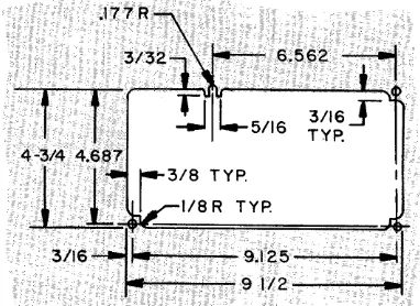
The unit is designed to be mounted in a I 0- inch wide space (with 10-inch panel), or a 19-inch RETMA equipment rack (with 19-inch panel or 10-inch panel with rack adapter). Complete dimensions of the unit are given in Figure 2-1. Natural cooling is sufficient to ventilate the unit when mounted in an open rack; however, mounting in a closed cabinet with other heat producing equipment requires that forced air or other methods of cooling be provided.
2.4 ELECTRICAL INSTALLATION
The electrical installation of the equipment consists
of wiring the interface mating connector (s) and ap-plying ac line power.
CAUTION]
Do not apply ac power to the reader with tape in position, unless external control signals are present to prevent simulta-neous energizing of the pinch roller and brake solenoids.
2.4.1 Mating Connector Wiring
2.4.1.1 Models 2540T and B2540T. Wire the 12/24-pin readhead mating connector (P2) and the 22/44-pin interface connector (P3) to the external equipment using Figure 2-2 as a guide. (Refer to Paragraph 1. 4.2 for reader interface requirements.)
2.4.1.2 Models 2540E, B2540E, 2540EP, B2540EP. Wire the 25/50-pin interface mating connector (J1) to the external equipment using Table 2-1 as a guide. (Refer to Paragraphs 1. 5. 3 and 1. 9 for special interface wiring considerations.)
2.4.2 AC Power
Apply 117 volts, 50 or 60 Hz line power to reader terminal board TB1 as follows:
AC Hot - TB1-2 AC Neutral - TB1-3 AC Gnd. - TB1-1
2.5 INITIAL INSTALLATION CHECKS
Following the installation of the equipment it is recommended that the following checks be per-formed to verify the proper operation of the equip-ment.
2.5.1 Voltage Checks
The reader operating voltages (from the external equipment or power supply) should be checked to ensure that they are within specified tolerances.
Externally supplied voltages to the basic unit should be checked at their external source. (Refer to
Paragraph 1-4 for voltage requirements). The electronics unit voltages (given in Table 2-2) can be checked at their respective edgeboard connections (refer to Figure 5-1).
o o
1..0
I
~
I
o
-.:t' 1..0
N
s:=
0
• .-1
td
--
CIS....
00
.s
.-4 I:f~
s:= Q)
~~
Q) • .-1oo~
~9-3/4
- - - 1 ... .-4 ·1/29/16
~ POWER SUPPLY ASSEMBLY
18-1/2444-1/2
0
01
5-1/4
O~
~---~~---IO--~~~===::Y---7-/-16--~}
19 ---i~.-j
0
~
Figure 2-1. Outline Drawing
CUTOUT FOR MOUNTING READER WITH IO·INCH PANEL
~1/4
....---1.,
..
11--
2 -3/8 (1/32o
o
1..0
I
~
I
o
-.:t' 1..0
[image:18.792.503.694.121.260.2]2540-M-500 Section II, Installation Paragraph 2. 5.2
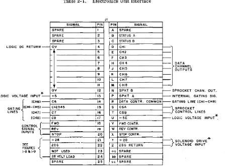
Table 2-1. Electronics Unit Interface
LOGIC DC RETURN
LOGIC VOLTAGE INPUT
{
(CH6)
GATING (CHI-CH5)
LINES (CH7)
(CHS) -* -CONTROL { SIGNAL INPUTS , ,
-SEE
r
FIGURES ~ I-S a 1-9
L
-SIGNAL SPARE SPARE SPARE OV ~ f-~ ~ f-~ OV +5 C6 CI2345 C7 CS FWD REV STOP +2S 2SGNOT USED 28 VOLT LOAD
SPARE
* SUPPLIED BY POWER SUPPLY ON (B)2540EP.
2.5.2 Performance Checks
JI PIN I 2 3 4 5 6 7 S 9 lO II 12 13 14 15 16 17 118 19 20 21 22 23 24 25
PIN SIGNAL
A SPARE
B STATUS A
C STATUS B
D CHI
E CH2
F CH3
H CH4
J CH5
K CH6
L CH7
M CHS
N SPKT B
P SPKT A
R DATA CONTR. COMMON
S CSA
T CSB
U -5E
V FWD CONTR.
W REV CONTR.
X STOP CONTR.
Y +2S
Z 2SG RETURN
aa SPARE bb SPARE
cc SPARE
~, ~ ~ ~ ). ~ ~ ~ t----~S DATA CHANNEL OUTPUTS
PROCKET CHAN. OUT.
~I NTERNAL GATING SIG.
~G
:=}
i - - - L
:=}
ATiNG LINE (CHI-CHS)
SPROCKET CONTROL LINES
OGle VOLTAGE INPUT*
*
SOLENOID DRIVE VOLTAGE INPUT
sive run and stop control signals and observe that tape motion follows the control signals.
The following checks should be performed to verify
the proper overall operation of the equipment. Table 2-2. Electronics Unit Voltage Measurements
a.· With ac power applied, and the Power switch in the RUN position, swing open top door (see Fig-ure 3-2) and observe that the capstan(s) rotate.
b. Load tape and prepare reader for operation in accordance with Section ill.
c. Operate external equipment to obtain
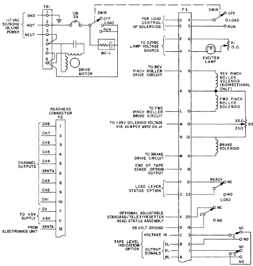
[image:19.615.111.558.95.426.2]Section II, Installation Figure 2-2
TBI
2
117 VAC { GND
50/60Hz H OT ---I~f-+---u
10, LINE :3
POWER NEUT -..-..r--r---,
CHANNEL OUTPUTS <
READ HEAD CONNECTOR
P2
,
-,r CH8 I CH7 2 CH6 :3 CH5 4 CH4 5 SPKTH 6 CH:3 8 CH2 9 CHI 10 ....
TO +5V SUPPLY
rv
+5V7
II
FRO ELECTRONICS UNI M T SPKTA 12 L..r-2540-M-500
r - - -
-SWIB
OFF FOR LOAD {
LOAD CONTROL
OF SOLENOIDS RUN
TO 22VDC {
LAMP VOLTAGE SOURCE RC-I
TO REV PINCH ROLLER DRIVE CIRCUIT
TO FWD PINCH ROLLER DRIVE CIRCUIT
TO + 28V SOLENOID VOLTAGE VIA JUMPER WIRE ON JI
TO BRAKE DRIVE CIRCUIT
END OF TAPE SENSE OPTION OUTPUT
LOAD LEVER{
STATUS OPTION
OPTIONAL ADJUSTABLE STANDARD/TELETYPESETTER HEAD STATUS ASSEMBLY
28 VOLT GROUND
{VOLTAGE IN
TAPE LEVEL
INDICATION 5L
OPTION OUTPUT
{~L
SIGNALS 8L
-SWIA
I
P:3
D 4
E 5
F 6
H 7
J 8
K 9
L 10
W 19
N 12
M II
V 18
Y 21
Z 22
X 20
S 15
C :3
B 2
I OFF RUN RI 15 Jl. EXCITER LAMP
REV PINCH ROLLER SOLENOID (BIDIRECTIONAL ONLY)
FWD PINCH ROLLER SOLENOID 25!l. 25.!l BRAKE SOLENOID
I---~~~I:J NC ONO LOAD ~--::::;IJNC NC ~---C~DNO NC R2
Figure 2-2. Interface Schematic Diagram, Basic Unit
[image:20.617.35.531.70.593.2]3.1 GENERAL
2540-M-500
SECTION III
OPERATING PROCEDURES
Section III, Operating Procedures Paragraphs 3.1 through 3.3.2
b. Move Tape Width selector to correct tape width position.
This section describes the operating controls, and the operating procedures for the equipment. It is assumed that the equipment has been properly in-stalled and that the initial installation checks have been performed as described in Section II.
c. Disengage front tape guides by moving Tape Load lever up (to LOAD position).
d. Thread tape through reader with channel one side of tape nearest panel (see Figure 3- 2).
3.2 OPERATING CONTROLS
The operating controls (see Figure 3-1) and their functions are described in Table 3-1.
e. Engage front tape guides by moving Tape Load lever down.
f. Move Power switch to RUN position. 3.3 OPERATING PROCEDURES
The unit is now prepared for tape read operation. The operating procedures consist of loading tape,
and controlling the reading of tape. 3.3.2 Tape Read
3.3.1 Loading Tape Tape reading is controlled by the application of run
and stop control signals from the external equipment. The control signal requirements are discussed in a. Move Power switch to LOAD position. Section 1.
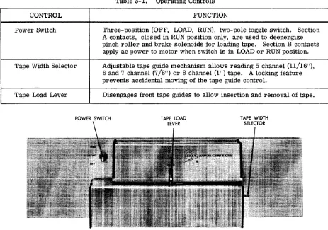
Table 3-1. Operating Controls
CONTROL FUNCTION
Power Switch Three-position (OFF, LOAD~ RUN), two-pole toggle switch. Section A contacts, closed in RUN pOSition only, are used to deenergize pinch roller and brake solenoids for loading tape. Section B contacts apply ac power to motor when switch is in LOAD or RUN pOSition.
Tape Width Selector Adjustable tape guide mechanism allows reading 5 channel (11/16"), 6 and 7 channel (7/8") or 8 channel (1") tape. A locking feature prevents accidental moving of the tape guide control.
Tape Load Lever Disengages front tape guides to allow insertion and removal of tape.
POWER SWITCH
Figure 3-1. Operating Controls
[image:21.612.97.560.405.730.2]Section III, Operating Procedures Figure 3-2
3-2
2540-M-500
Figure 3- 2. Tape Path
2540-M-500 Section N, Theory of Operation Paragraphs 4.1 through 4.3.1
SECTION IV
THEORY OF OPERATION
4.1 GENERAL
This section describes the mechanical and electrical operation of the basic Model 2540 and its two major subassemblies; the electronics unit and the power supply. In addition, the optional end-of-tape sensor is discussed.
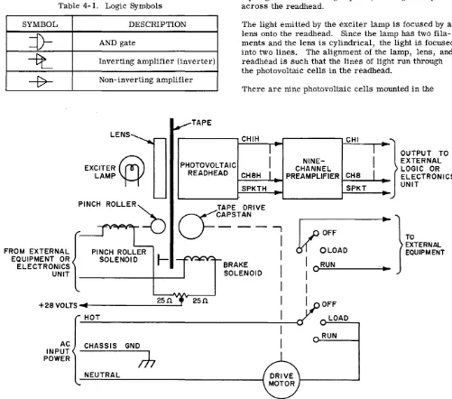
4.2 LOGIC SYMBOLS
The logic symbols used in this section are illustrated and described in Table 4-1.
SYMBOL
=n-~
-f7-Table 4-1. Logic Symbols
DESCRIPTION
AND gate
Inverting amplifier (inverter)
Non-inverting amplifier
LENS
EXCITER~
LAMP'f-t'
TAPE
PHOTOVOLTAIC READHEAD
4.3 FUNCTIONAL DESCRIPTION
403.1 Basic Unit
The basic unit (Model 2540T) consists of a tape trans-port, photovoltaic readhead and solid-state preamp-lifier. (See Figure 4-1.) When the Power switch is set to the LOAD or RUN position, input ac power is applied through the switch to the drive motor. The dri ve motor turns the drive capstan. When the con-trol circuits (external to the basic unit) energize the pinch roller solenoid, the pinch roller presses the tape against the rotating capstan, driving the tape across the readhead.
The light emi tted by the exciter lamp is focused by a lens onto the readhead. Since the lamp has two fila-ments and the lens is cylindrical, the light is focused into two lines. The alignment of the lamp, lens, and readhead is such that the lines of light run through the photovoltaic cells in the readhead.
There are nine photovoltaic cells mounted in the
CHIH a
I-I
NINE-CHANNEL CH8HI
PREAM PlIFI ER-SPKTH
-CHI
CH8 SPKT
I
I
J a
.
.--.OUTPUT TO EXTERNAL LOGIC OR ELECTRONICS UNIT
PINCH ROLLER~
cY
CAPSTAN TAPE DRIVE- - -
-,
I
V
OFF TOEXTERNAL EQUIPMENT FROM EXTERNAL
EQUIPMENT OR ELECTRONICS UNIT
PINCH ROLLER
f-SOLENOID+28VOLTS~d~---2_5_n~
AC INPUT POWER
HOT
CHASSIS GND
/-h
NEUTRAL
25£1
BRAKE SOLENOID
I
. OLOADI
I
I
ORUNI
I
I
y O F F
I
LOADI
RUNI
Figure 4-1. Basic Unit, Functional Block Diagram
[image:23.613.71.572.284.726.2]o o
Ii.)
I
::g
I
o
~
Ii.) C"I
FRO EXTERNA EQUIPMEN
FROM EXTERNAL EQUIPMENT <
M
L ( T
,..
FORWARD
~FWD
FORWARD CONTROL
REVERSE
~REV
REVERSE CONTROL
~BRAKE
STOP STOP CONTROL
+28V
I
I
REGULATORI
+24V LAMP VOLTAGE'"
POSITIVE FEEDBACK TO
READ HEAD SPROCKET AMPLIFIER DATA ENABLE
CI2345 ENABLE C6 ENABLE C7 ENABLE C8 ENABLE CSA ENABLE CSB ENABLE
IINTEGRA~l
CIRCUITS
1
I
11\
r CHIH
I
SCHMITT I CHILJ
l
TRIGGERJ
CH2H1\
TO
I
SCHMITTI
CH2>
BASICLJ
I
TRIGGERI
UNITCH3H
1\
I
SCHMITTI
CH3LJ
I
TRIGGERI
CH4H1\
J
SCHMITTI
CH4..
LJ
l
TRIGGERJ
FROM CH5H
1\
READHEAD~
I
SCHMITTI
PREAMPLIFIERS CH5
LJ
l
tRIGGERJ
CH6HD---1
SCHMITTI
CH6 TRIGGERI
CH7H
1\
I
SCHMITTI
CH7J
I
TRIGGERI
CH8HD---1
SCHMITTI
CH8I
TRIGGERI
'"
SPKTH1\
V
I
SCHMITTI
SPKTAJ
l
TRIGGERJ
I
I
D---1
SCHMITTI
I
SPKTB TRIGGEJ
L_
---Figure 4-2. Electronics Unit, Logic Diagram
...
)
TO
EXTERNAL EQUIPMENT
o o
Ii.)
I
::g
I
o
~
[image:24.792.63.723.80.563.2]2540-M-500 Section IV, Theory of Operation
readhead, one for each channel on the tape. (The 2540 can read five through eight-level tape so that, when reading eight-level tape, nine cells are re-quired, one for each data channel and one for the sprocket channel.) As the tape moves across the readhead, it prevents the light from striking the cells. However, each time a perforation (hole) in the tape passes over the readhead, light is allowed to pass and strike a cell, causing the cell to generate a volt-age. The voltage is applied to the preamplifier. The preamplifier amplifies and inverts the photo-voltaic cell output and applies it to the external logic to indicate that a ONE bit has been read from the tape. As long as the hole in the tape is over the cell, the preamplifier output corresponding to that cell remains at +5 volts. When the hole has passed over the cell, the light is cut off, the cell voltage is turned off, and the preamplifier output is returned to
o
volts. As long as the pinch roller solenoid is energized, the tape is moved across the. readhead and data is read from the tape.To stop tape motion, the pinch roller solenoid is deenergized and the brake solenoid is energized. The pinch roller now moves away from the capstan, so that drive power is no longer applied to the tape, and the brake armature squeezes the tape between itself and the poles of the brake coil, sharply in-creasing the friction drag on the tape and stopping the tape. To start tape motion again, the brake so-lenoid is deenergized and the pinch roller soso-lenoid is energized.
The bidirectional reader operates in the same man-ner as just described for the unidirectional unit, except that the motor drives two capstans (forward and reverse), and two pinch roller assemblies con-trol tape motion. To drive the tape forward, the forward pinch roller solenoid is energized; to drive the tape in reverse, the reverse pinch roller solen-oid is energized.
4.3.2 Electronics Unit
Note
The following discussion assumes that the reader is familiar with standard logic terminology.
The electronics unit performs two distinct functions: tape motion control and output data control. In add-ition, the electronics unit provides regulated +24 volts dc for the readhead exciter lamp in the basic unit.
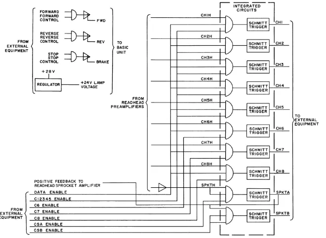
To enable external control of tape motion, the elec-tronics unit uses three AND-gate/inverter circuits. (See Figure 4-2.) Since all three circuits operate in the same manner, only the "forward" circuit is described.
The FORWARD control signal is applied to the AND gate in the forward circuit by the external equipment.
If this signal is at logical ONE (+5 volts or floating), the AND gate is enabled. (This signal may be con-trolled by the Power switch through the external
Paragraph 4.3.2
circuits.) If the FORWARD signal now goes to logical ONE, the AND gate is satisfied and its output goes to logical ONE, turning on the inverter. The output of the inverter energizes the forward pinch roller solenoid in the basic unit. As long as both AND gate inputs remain at ONE, the inverter is held on and the pinch roller solenoid is energized. If either one of the AND gate inputs goes to logical ZERO (0 volts), the AND gate output goes to ZERO, the inverter is turned off, and the pinch roller solenoid is deener-gized.
The electronics unit provides gating and pulse shap-ing for the data and sprocket pulses generated by the readhead in the basic unit. Each data channel output of the readhead is applied directly to an AND-gate/ Schmitt trigger circuit. The sprocket channel output is amplified by a non-inverting amplifier and then applied to an AND-gate/Schmitt trigger circuit. All three inputs of an AND gate must be at logical ONE for that gate to be satisfied. One input of each data gate (channels 1 through 8) is connected to the data control line. Therefore, to permit data from the readhead to be gated through the electronics unit, the external equipment must place a logical ONE (+5 volts or floaUng) on the data control line. (A control line inhibits a gate when it is grounded.) In
addition, .control lines are provided to set up the electronics unit for the level of tape being read. If
five-level tape is being read, control line C 12345 is placed at logical ONE. Control line C6 is used to enable data to be gated through the channel 6 AND gate; control lines C7 and C8 are used to enable the gating of data in channels 7 and 8 respectively. A sprocket signal (SPKTA) generated by the electronics unit is applied to the readhead sprocket circuit, as a positive feedback signal; reducing the time required. for the sprocket preamplifier to reset. SPKTA may also be routed to the control lines to gate the data through the electronics unit.
The sprocket channel AND gates are controlled by the signals placed on control lines CSA and CSB. To enable the SPKTA (Sprocket A) signal to be generat-ed, the CSA control line is placed at logical ONE. Both the CSA and CSB control lines are put at logical ONE to enable generation of both the SPKTA and SPKTB signals. (Since signal SPKTA is used to satisfy the AND gate which provides the SPKTB sig-nal, SPKTB can never be generated without SPKTA· being present and both CSA and CSB are required to generate SPKTB. )
The AND-gate/Schmitt-trigger circuit used in chan-nel 1 operates in the following manner (since all 10 AND-gate/Schmitt-trigger circuits contained in the electronics unit operate in the same manner, only the channel 1 circuit is described).
When a hole is detected in the tape, the basic unit preamplifier places signal CH1 at a logical ONE. (See Figure 4-2.) If the data and C12345 control lines are at logical ONE, the output of the channel 1 AND gate goes to logical ONE, triggering its assoc-iated Schmitt trigger. The Schmitt trigger shortens the rise and fall times of the input signal. When the
Section IV, Theory of Operation Paragraphs 4.4 through 4.4.2
2540-M-500
hole has passed the readhead, signal CH1 returns to ZERO, causing the AND-gate and Schmitt-trigger outputs to go to ZERO.
4.4 CIRCUIT DESCRIPTION
4.4.1 Basic Unit, Detailed Analysis
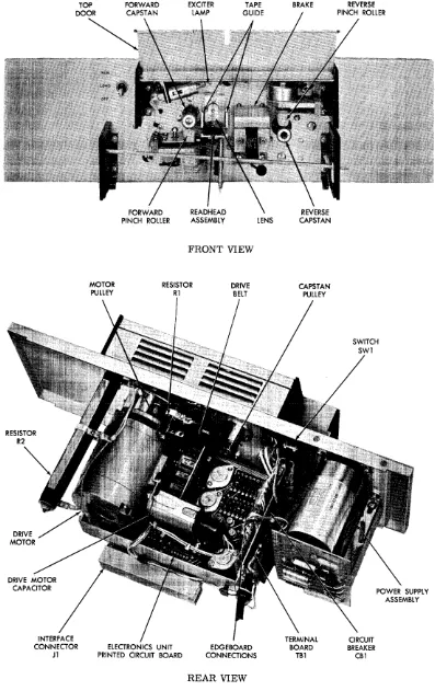
4.4.1.1 Tape Drive System. Primary mechanical power for the tape drive system is provided by drive motor M1. (See Figure 7-1.) When Power switch SW 1 is set to the LOAD or RUN position, the input ac line power is applied to the motor through circuit breaker CB1 and section B of SW1. (Network RC-1 suppresses arcing across the switch terminals when the switch setting is changed.) Since the input power is single-phase and M1 is a two-phase motor, motor capacitor C 1 is supplied to provide a two-phase input to the motor.
In unidirectional units operating at 200, 300, or 400 characters per second, the capstan is mounted directly on the output shaft of Ml. In unidirectional units operating at other speeds, the capstan is driven by M1 via a belt-and-pulley arrangement. In bidi-rectional units, the reverse capstan is mounted directly on the, shaft of M1, while the forward cap-stan is driven via a belt and pulley arrangement.
To move tape, the pinch roller solenoid (forward or reverse) must be energized and the brake solenoid must be de energized by the external circuits con-trolling the 2540; to stop tape motion, the brake solenoid must be energized and the pinch roller solenoid {forward or reverse} must be deenergized by the external circuits. Since all solenoids in the 2540 operate in the same manner, only the forward pinch roller solenoid is described.
The forward pinch roller solenoid in connected to pins Land 10 on connector P3 and to one side of resistor R2. The slider of R2 is connected to pins Wand 19 of P3. A +28 volt dc supply voltage is applied through pins Wand 19 to the slider of R2 by either the external equipment or (on Models 2540 EP and B2540EP) by the power supply contained in the 2540. To energize the forward pinch roller solenoid, the external equipment grounds either pin L or 10 of P3, thereby connecting the solenoid and one-half of R2 across the 28-volt supply. To deenergize the solenoid, the ground is removed.
4.4.1.2 Tape Read System. When a hole (ONE bit) in the tape passes over the readhead, light strikes a photoVoltaic cell in the readhead (as described in Paragraph 4. 3. I) causing the cell to produce a voltage. The positive side of each cell is held slightly positive by CR1 and R23 (as shown in Figure 7-1); while the negative side of each cell applies a negative voltage to the preamplifier when it is struck
by light. The data channel cells drive transistors Q1 through Q8; the output of the sprocket channel cell is applied to Q9. Since all the data channel amplifiers (Q1 through Q8) are identical, only the channel 1 (Q1) and sprocket channel (Q9 and Q10) amplifiers are described.
In the quiescent state, with no light applied to the channel 1 cell, the positive voltage applied to the base of Q1 through resistor R1 maintains Q1 satur-ated so that the output voltage of Q1 (at the collector) is 0 volts. In addition, the voltage applied to the common side of the cells by CRI and R23 keep the leakage current at a minimum. When light strikes the channel 1 cell, the cell applies a negative voltage to the base of Q1; Q1 is turned off and its collector voltage goes to +5 volts, indicating that a ONE bit has been read from the tape.
With no light applied to the sprocket channel cell, the positive voltage applied to the base of Q9 main-tains Q9 saturated, and the voltage at the collector of Q9 is 0 volts. This O-volt level is applied to the electronics unit or external equipment, through con-nector P2 pin 6, SPKTH. In addition, the O-volt level of SPKTA (from the electronics unit or exter-nal equipment) applied to the base of Q10, through resistor R20, maintains Q10 saturated. When light strikes the sprocket channel cell, the cell applies a negative voltage to the base of Q9. As the base volt-age of Q9 begins to go negative, this voltvolt-age change is inverted and amplified, causing the collector voltage of Q9 to go positive. This positive voltage is fed to the electronics unit or external equipment as SPKTH; causing SPKT A, at P2 pin 12, to go positive. This positive going voltage is amplified and inverted by Q10, and applied to the base of Q9, reinforcing the original input and aiding in turning off Q9. In this way, Q10 reduces the time required to turn off Q9. When Q9 is off, its collector volt-age rise s to +5 volts indicating that a sprocket hole has been detected.
When the light is removed from the sprocket channel cell, the base voltage of Q9 is driven positive. When Q9 again begins to conduct and its collector voltage goes negative, Q10 again provides positive feedback, reducing the time required to saturate Q9 and drive its collector voltage to 0 volts.
4.4.2 Electronics Unit, Detailed Analysis
The electronics unit contains four discrete compo-nent circuits (three solenoid control circuits and a voltage regulator) and 10 integrated circuits (AND-gate/Schmitt-trigger combinations). Since all three solenoid control circuits are identical, only the cir-cuit that controls the forward pinch roller solenoid is described.
The forward pinch roller solenoid control circuit consists of an AND gate (CRI-CR2) and a solenoid driver (QI-Q2). (See Figure 7-1.) Inouts from the external control cirCUIts are applied to the cathodes
2540-M-500 Section IV, Theory of Operation Paragraphs 4.4.3 through 4.4.4
of diodes CRI and CR2. If the voltage on the cathode of CRI is 0 volts, that diode is forward biased, and the output of the AND gate (taken from the anodes of CRI and CR2) is clamped to 0 volts. If the voltages on the cathodes of both CRl and CR2 are driven to +5 volts (or if the cathodes are left floating), the diodes are no longer forward biased and the output of the AND gate goes positive.
The output of the AND gate is applied to the base of transistor Ql. Transistors Ql and Q2 form a Dar-lington amplifier which functions as follows; Ql acts as an emitter-follower circuit, and therefore reduces the voltage on its base at its emitter and pro-vides current amplification for the base circuit of transistor Q2. (During the time Q2 is cut off the collector current of Ql passes through the pinch roller solenoid, but this current is not large enough to energize the solenoid.) When the voltage at the emitter of Ql is approximately 0 volts, Q2 is turned off. Under these conditions capacitor Cl charges to +28 volts through resistor R2, in the basic unit. (See Figures 7-1 and 7-2.) When the emitter voltage of Ql goes positive, Q2 is turned on and saturated. When Q2 first turns on, Cl discharges through Q2 and the pinch roller solenoid, providing a large initial current pulse through the solenoid and redu-Cing the time required for the solenoid to become energized. The collector current of Q2 then main-tains the solenoid energized as long as Q2 is held on. When the AND- gate output returns to 0 volts, the emitter voltage of Ql goes to approximately 0 volts, turning off Ql. The solenoid current path is now interrupted and the solenoid is deenergized; however, because a magnetic field was built up around the solenoid when it was energized, voltage is induced in the solenoid by the collapsing field. The voltage induced in the solenoid forward biases diode CR3, causing an induced current to flow through CR3 and resistor R3, and thereby dissipating the energy con-tained in the solenoid magnetic field and preventing large voltage spikes from being induced in the sole-noid.
The lamp voltage regulator maintains the voltage sup-plied to the exciter lamp in the basic unit at 24 volts. The +28 volt power from the dc power supply is ap-plied to the voltage divider composed of resistor RIO and Zener diode CRI0. Zener diode CRI0 maintains the base voltage of transistor Q7 constant, eliminating the voltage variations which appear in the +28 volt supply power. If the 28-volt supply voltage goes more positive, the emitter voltage of Q7 goes more positive; however, in going more positive, the emit-ter voltage reduces the forward bias on the base of Q7, increasing the emitter-to-collector resistance to Q7 and causing the voltage change on the emitter to be virtually eliminated. (The change on the emit-ter is not eliminated, but the magnitude of the change is limited so that the change is negligible.) If the supply voltage becomes less positive, the effect is to increase the bias on the base of Q7, reduce the emitter-to-collector resistance of Q7, and again make the voltage change on the emitter negligible. Emitter-follower Q7 provides current amplification for the
base circuit of transistor Q8. Emitter-follower Q8 operates in the same manner as Q7 and provides the constant supply voltage to the exciter lamp.
The integrated circuits which gate and shape the out-put pulses of the preamplifier in the basic unit are contained in five dual in-line packages. Since these circuits are not repairable, a detailed analysis of these circuits is not presented. (For a functional description of the integrated circuits, refer to Paragraph 4.3.2. )
4.4.3 Power Supply, Detailed Analysis
The ac input power is applied to the primary windings of transformer Tl. (See Figure 7-2.) Connected to the secondary of Tl are two full-wave rectifiers. One rectifier (composed of diodes CRI and CR2) pro-vides a positive dc output, while the other rectifier (diodes CR3 and CR4) provides a negative output. The output of the negative rectifier is filtered by the RC filter composed of resistor R3 and capacitor C2. Resistor R3 and Zener diode CR6 form a voltage divider which reduces the -28-volt level available at the rectifier output to -5 volts.
The output of the positive rectifier is filtered by capacitor Cl. The +28-volt power at the positive plate of C 1 is made available at the output of the power supply. (Resistor R6 functions as a bleeder resistor for the positive supply.) The circuit com-posed of resistors Rl, and R2, and Zener diode CR5, regulates the +5-volt output of the supply. Zener diode CR5 and Rl form a voltage divider which provides a constant reference voltage of +5. 6 volts. Capacitor C3 filters the +5 volt output.
4.4.4 End-of-Tape Sensor, Detailed Analysis
The end-of-tape sensor consists of a photoconductive cell, a cell exciter lamp, a lamp voltage regulator, and a transistor amplifier. (See Figure 7-3. ) The lamp voltage regulator consists of transistor Ql and diodes CR1 and CR2. This circuitandthe lamp are connected in series with the readhead exciter lamp and lamp rheostat Rl, located in the basic unit. The diodes and the base-emitter junction of Ql drop ap-proximately 1. 2 volts, providing this voltage to the lamp. The end-of-tape sensor is mounted on the 2540 so that the tape passes between the lamp and the photo-conductive cell. When there is tape between the lamp and the cell, the light striking the cell is re-duced, causing the cell to exhibit a high resistance. The voltage across the cell forward biases tran-sistor Q2 and the output of the end-of-tape sensor (taken from the collector of Q2) is 0 volts.
When the end of the tape has passed through the end-of-tape sensor, the light from the lamp is allowed to strike the cell. The cell resistance fails, causing the voltage drop across the cell to become approximately 0 volts. Transistor Q2 is not cut off, and the output of the end-of-tape sensor rises to approximately +5 volts.