Abstract- The five axes capabilities used on Computer Numerical Controlled (CNC) machine tools are becoming increasingly common in the manufacturing industry. However, the problem of modeling of combined linear and rotary axes through the kinematic chain, and their effect on the translation and rotation errors of the cutting tool to the machine has not been addressed. A study of developing the error modeling on an industrial five-axis CNC machine tool will enable the understanding of the accuracy performance of machine and therefore to minimize the error by mechanical adjustment or error compensation methods. A mathematical modeling to determine the volumetric error can be developed from the kinematic error models accounting for the unique structural configuration of a CNC machine tool. Since there were discussions on the modeling of three-axis CNC machine tool done by previous research publications [1-3] hence, the rotary table modeling of five-axis CNC machine tool and the combination of both will be the main subject in this paper. The effects of the positioning errors of machine’s axes on the accuracy (translation and rotation) of the cutting tool in its workspace will also be discussed. The development of the mathematical model shows that the angular deviations are independent of translation errors. However, the tool point deviations are dependent on both translational and rotational errors. Moreover, the rotational and translation errors are divided separately into the 3x3 and 3x1 transform matrix respectively. The construction of this mathematical model will be then verified by various experiments, showing the validity and effectiveness of the presented methods. This is important to indicate that it can be used for multi-axis machine tools as a means of calibration and precision purpose.
Keywords—Volumetric Error, Geometry Modeling, Five-axis CNC Machine, Kinematic Configuration, Machine Calibration.
Notation:
Ex(X), Ey(X), Ez(X) rotational errors in the X, Y, Z directions along the X axis
Ex(Y), Ey(Y), Ez(Y) rotational errors in the X, Y, Z directions along the Y axis
Ex(Z), Ey(Z), Ez(Z) rotational errors in the X, Y, Z directions along the Z axis
α, β1, β2 squareness errors between the XY, XZ and YZ axes
Seng Khim, Tan is with the University of Nottingham Malaysia Campus, (corresponding author to provide phone: 603-8924 8350; fax: 603-8924 8017; e-mail: [email protected]).
Chin Keong, Lim was with University of Nottingham Malaysia Campus. He is now with the Department of Mechanical, Manufacturing and Material, (e-mail: [email protected]).
δx(X), δy(Y), δz(Z) positional errors in the X, Y, Z axes respectively
δx(Y), δz(Y) straightness errors in the X, Z directions along the Y axis
δx(Z), δy(Z) straightness errors in the X, Y directions along the Z axis
δy(X), δz(X) straightness errors in the Y, Z directions along the X axis
RX, RY, RZ rotational matrix along the X, Y, Z axes RC, RA rotational matrix along the C, A axes TX, TY, TZ translational matrix along the X, Y, Z axes TC, TA translational matrix along the C, A axes Xa, Ya, Za actual coordinate data
X, Y, Z nominal coordinate data Xt, Yt, Zt tool length offset data ∂XA(θx), ∂YA(θx),
∂ZA(θx)
radial and axial error of rotational A axes ∂XC(θz), ∂YC(θz),
∂ZC(θz)
radial and axial error of rotational C axes фA, λA, γA tilt error or the error of the rotational A axes фC, λC, γC tilt error or the error of the rotational C axes ∆X, ∆Y, ∆Z systematic error components in the X, Y, Z
directions
θx, θy, θz rotation angle about X, Y, Z axes
I. INTRODUCTION
IVE -axis Computer Numerical Control (CNC) machines are widely used in the manufacturing industry for machining operations. This machine is becoming increasingly popular because of their ability to machine geometrically complex work pieces efficiently and with higher dimensional accuracy. This is due to the machine ability to take full advantage of the two additional rotary axes to adjust the tool orientation with respect to the work piece.
In this paper, the major point is focused on the geometric and volumetric errors in five-axis CNC machine tools. A general mathematical model, called Comprehensive Computer Model has been established. It can be used to estimate the volumetric errors from the parametric and rotary table errors whereby it is applicable to most of the five-axis CNC machines and hence to satisfy high precision requirement. Furthermore, all the parametric and rotary table errors will be converted into the matrix form. Initially, this modeling method has been developed by H.J. Park, M. Burdekin and G.N. Peggs [4] in the calibration of Coordinate Measuring Machines (CMM).
One of the major difficulties in using the parametric error components such as positional errors, straightness errors, and squareness errors is the deviations of error accordingly to their
Modeling the Volumetric Errors in Calibration
of Five-axis CNC Machine
Seng Khim, Tan and Chin Keong, Lim
measurement location. Therefore, the effect of measurement offsets should be taken into account when developing transformation rules for the parametric error components. Besides that, the 3 rotational and 3 translational errors will also be considered for 2 rotary axes (C, A-axis).
The identification of volumetric error can be classified into two alternative approaches depending on the methods used to identify the volumetric error: the direct workspace identification method and the error synthesis method. The first approach directly identifies the volumetric error of 3D machine by using artifacts with known dimensions placed on the machine. The difference between measurement and the known length is used to calculate the volumetric error. Because of the limitations of the direct identification method and progress in laser interferometer measurement techniques, the synthesis method is applied in this paper to analysis the volumetric error. The entire mathematical model will be constructed in this paper and the process of measurement will be discussed in the next.
II. OVERVIEW OF TRANSFORMATION MATRICES
Generally, machine tools are built by the combination of fixed links, moving slides (prismatic joints) and rotating joints (revolute joints). These components consist of a closed chain between the tool contact point and the work piece. In an attempt to develop a generalized error model of five-axis machine tools, it is important to first define its model through structure of the machine. The transformation matrices model offers an effective approach to accomplish this goal since such a matrix is capable of translational, as well as, rotational transformations.
To represent the relative position of a rigid body in three-dimensional space, with respect to a given coordinate system, a 3 x 3 homogeneous transformation matrix (HTM) and 3 x 1 matrices is needed. The 3 x 3 (HTM) represents the rotational matrices and 3 x 1 is for translational matrices. Both of these transformation matrices represent the coordinate transformation to the reference coordinate system {X’, Y’, Z’} from that of the rigid body frame {X, Y, Z}.
Rotational, ; Translational, ;
III. MODEL DESCRIPTION AND VOLUMETRIC ERROR MODELING
Calculation of the volumetric error of a five-axis CNC machine depends on the kinematic configuration of the machine itself, and a computer program will be developed to approach the most common types of five-axis CNC machine in use.
Most common five-axis CNC machines have three translational axes (T-axis) and two rotational axes (R-axis). The other configurations (i.e. 2T3R, 1T4R) are designed and used for special applications. The 3T2R configuration can be subdivided into smaller family based on the location of the rotational axes with respect to the translational axes. The common configurations are:
a) TTTRR – The cutting tool is supported by a double pan head.
b)RTTTR – The work piece is supported by a turntable and the cutting tool is supported by a single pan head. c)RRTTT – The work piece is supported by a double
turntable.
The three translational axes in the above configurations describe a fixed Cartesian frame. This construction design presents less engineering difficulties and complexity because of the translational axes also make up the machine’s structure. These three main configurations can be further broke down to a few subgroups. Although the alternative design which involves a moving or rotating Cartesian frame will increase the degree of structure complexity, however, it may be required for some industry for special machining operation.
When the parametric and rotary table errors components are obtained for a working volume of a machine, the volumetric error map can be constructed using rigid-body kinematic chains. Two kinematic models are explained in this report.
Besides that, MAPLE [5] was used to conduct the symbolic multiplication of the matrices in this paper. MAPLE is a powerful symbolic mathematical package developed by the University of Waterloo.
IV. TYPE OF ERROR
Error is defined as the difference between the actual response of the machine to a command issued according to the accepted protocol of that machine’s operation and the response to that command anticipated by the protocol.
Accuracy is defined as the degree of conformity of the finished part to dimensional and geometric specifications. Limits of achievable dimensional accuracy of machined parts are directly related to the errors of the machine tool from which such parts are being produced.
Volumetric errors/accuracy represents the overall errors/accuracy of the machine too. Therefore, it has become one of the important indices to represent the quality of such machines.
In a typical CNC machine tool, more than 70% of the geometric errors are slowly varying with time and are related to the geometry of the machine tool. This type of error also defined as “Quasistatic errors” [1]. In the five axis machine tool technology, the error terms are commonly expressed as:
(a) Positional errors;
(b) Horizontal and Vertical Straightness errors; (c) Angular errors;
(d) Squareness and Perpendicularity errors; (e) Rotary table errors.
six geometric error components and three squareness errors. So the total errors are 21, and it is also defined as the parameter errors. Besides that, there are 6 rotary table errors for each rotating axis (C and A). These terms refer to the errors of the individual axes and those between the axes of the machine tool. Furthermore, the measurement technology is centered on the measurement of the errors of a single axis. For example, laser interferometers are capable of measuring positioning, angular, straightness and squareness errors of an axis. In addition, double ball bar (DBB) is able to measure nonlinear errors in the guide way system [6]. Therefore, there is a critical need for the development of a volumetric error map at the cutting tool tip as it moves around in the work space.
Figure 1: Six DOF parametric errors along a machine axis.
V. ROTARY TABLE ERROR COMPONENTS
For most of the five-axis machine tool configurations, the rotary table provides two degrees of freedom of motion for the orientation of the work piece. The two axes of this orientation are also called C and A-axis. So, the general view for error vector of the tool position due to the three linear axes and the two rotational axes:
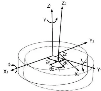
In this part, we are concerned with the error modeling of the two rotational axes, E(C, A). First, consider the error model for the rotational axis with respect to the Z-axis. In general, there exist 6 error components for a rotating axis as showing at below (Fig. 2); three translation errors (∂x(θ), ∂y(θ), ∂z(θ)), two rotational errors (ф, λ) and one angular error with respect to the rotational axis (γ). The axis that is rotating about Z-axis is called C-axis. Besides that, error components for the A-axis, which rotate with respect to the X-axis, can be similarly defined. Thus, there are a total of 12 errors components for rotary tables in the C- and A-axis of five-axis machine tools. Because of the six error components, the rotary table coordinate frame is changed. Let X1 Y1 Z1 be the original
(or error-free) coordinate frame, and X2 Y2 Z2 be the changed
coordinated frame (Fig. 2). Then, the relationship between the two coordinated frames can be represented by 3x3 and 3x1 transform matrix.
Figure 2 shows a turn table which rotates about Z-axis by an angle θz +γ, where γ is the error about the rotation axis, with 2 radial errors ∂X, ∂Y and an axial error of ∂Z, as well as tilt errors ф and λ.
Figure 2: Six error components for the rotary table.
VI. RRTTT MODEL OF FIVE-AXIS CNC MACHINE
A. Error Analysis of RRTTT(3) Model
Fig. 3 RRTTT(3) Model of CNC Machine
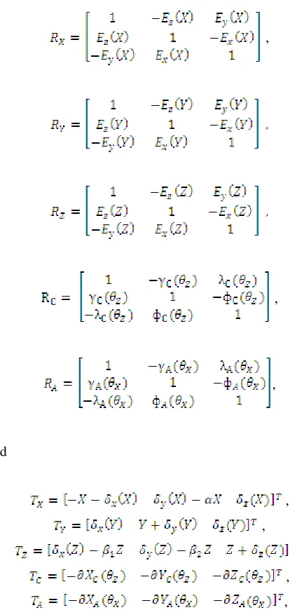
[image:3.612.335.541.431.628.2]where RX, RY, RZ, RC and RA are the rotational matrices and TX, TY, TZ, TC, and TA are the translational vectors along the X, Y and Z axes respectively:
,
,
,
And
, ,
, ,
,
where δx(X), δy(Y), δz(Z) are positional errors, δy(X), δz(X), δx(Y), δz(Y), δx(Z) and δy(Z) are straightness errors, Ex(X), Ey(X), Ez(X), Ex(Y), Ey(Y), Ez(Y), Ex(Z), Ey(Z) and Ez(Z) are rotational errors along the X, Y and Z axes and α, β1, β2 are squareness errors between the XY, XZ and YZ axes respectively. Besides that, for rotary table errors (C-, A-axis), ∂XA(θx), ∂YA(θx), ∂ZA(θx), ∂XC(θz), ∂YC(θz) and ∂ZC(θz) are radial and axial error of rotational C and A axes, фA, λA, γA, фC, λC and γC are tilt error or the error of the rotational C and A axes. Notice that ∆X = Xa – X – Xt, ∆Y = Ya – Y – Yt and ∆Z = Za – Z – Zt. Besides that, if small angle approximation is made Cosλc =1 and Sinλc=λc and second order term such as фcλc are neglected, then the volumetric errors (∆X, ∆Y, ∆Z) can be simplified to;
VII. CONCLUSION
This paper describes a new and simple analytical method to obtain the total volumetric (position and orientation) error at the tool throughout the workspace due to geometric errors of individual components on a five-axis CNC machine tool. In order to integrate effectively the geometric errors and rotary table errors in five-axis CNC machine, an integrated volumetric error model has been proposed with explicit equations. The most RRTTT model configurations have been completed in this report. The error model was formulated in transformation matrices form for inaccurate links, as well as sliding and rotary joints of the existing RRTTT type machine tool. The theoretical development of this work is the incorporation of the angular and straightness errors into the model. At this stage it is believed that the software will be developing in the next can be used as a tool to estimate the volumetric errors map.
[image:4.612.59.266.113.548.2]derived to cover most commercially available five-axis CNC machine of RRTTT models.
Considering that perfect alignment in practice cannot be guaranteed by any means, several trial and error attempts should be made to obtain close alignment. Nevertheless, the various experimental results convinced us that the methods presented can be used as a means for the maintenance of, the calibration of, and the precision enhancement on the five-axis machine tools.
The work presented in this paper will serve as the foundation of a long research project in (five-axis) machine tool technology. It is appreciated with hope to obtain further industrial assistance in generating test data and in verifying the error models.
VIII. SUMMARY
Improving the machine accuracy of five-axis machine tools has been one of the main focuses of research on five-axis CNC machine tools in this paper. As both linear and rotational axes are presented in five-axis machine tools, the kinematic interaction leads to a complicated mathematical model, which increases the difficulty in applying related techniques in industry. This study presents a new technique to analyze the geometric error of five-axis CNC machine tools. There are total 21 parametric errors in linear axes and 12 kinematic errors associated with rotary table axes(C, A-axes) of the machining center are considered and identified theoretically by mathematical transformation matrices form. The volumetric error map is developed based on the result of ∆X, ∆Y and ∆Z. The construction of volumetric error map is very useful to describe every single position (X, Y, Z) error in the machine tool. Generally, the volumetric error map is utilized in comparing the actual path to the nominal path and improves the repeatability and precision of the five-axis CNC machine tools. In addition, it is used to describe the total error in position and orientation of the machine end effectors (spindle, cutting tool or stylus tip) within its working volume with respect to the object acted upon such as a work piece. Finally, the error compensation model was verified as being able to effectively counter back the geometric errors of a five-axis machine tool. Furthermore, the error compensation technique established in the present study can also be applied in other types of five-axis machine tools.
ACKNOWLEDGMENT
First and Foremost, the author would wish to acknowledge assistance and input from Dr. Lim Chin Keong of the Department of Mechanical, Materials and Manufacturing Engineering at University of Nottingham Malaysia Campus (UNMC). His willingness to motivate and inspiration has contributed tremendously to the research work.
Besides, the author is grateful to the authority of UNMC for providing a good environment and facilities to complete this research. Special gratitude is dedicated to the Department of Mechanical, Materials and Manufacturing Engineering, UNMC, for the research funding as well as technical support to enable the work reported to be undertaken.
Finally, an honorable mention goes to our families and friends for their understandings and supports on me in completing this project. Without helps of the particular that mentioned above, I would face many difficulties while doing this research.
REFERENCES
[1] V.Kiridena and P. M. Ferreira, “Mapping the effects of positioning errors on the volumetric accuracy of five-axis CNC machine tools”, Int. J. Mach. Tools Manufact. 33 (3), pp.417 (1993)
[2] A. K. Srivastava, S.C. Veldhuis, M.A. Elbestawit, “Modeling geometric and thermal errors in a five-axis CNC machine tool”, Int. J. Mach. Tools Manufact., 35 (9), pp.1321-1337 (1995).
[3] W.T. Lei, Y.Y. Hsu, “ Accuracy test of five-axis CNC machine tool with 3D probe-ball. Part II: Errors estimation.” Int. J. Mach. Tools Manufact., 42(8), pp.1163-1170 (2002).
[4] H.J. Pahk, M. Burdekin and G.N. Peggs, “Development of virtual coordinate measuring machines incorporating probe errors”, Proceedings of the Institution of Mechanical Engineers, Part B: Journal of Engineering Manufacture 212 B7 (1998), pp. 533–548.
[5] MAPLE, Symbolic Computation Group, University of Waterloo, Waterloo, Ontario, Canada N2L 3L3.