Abstract—Ternary codes have been widely used in radar and communication areas, but the synthesis of ternary codes with good merit factor is a nonlinear multivariable optimization problem, which is usually difficult to tackle. To get the solution of above problem many global optimization algorithms like genetic algorithm, simulated annealing, and tunneling algorithm were reported in the literature. However, there is no guarantee to get global optimum point. In this paper, a novel and efficient VLSI architecture is proposed to design Ternary Pulse compression sequences with good Merit factor. The VLSI architecture is implemented on the Field Programmable Gate Array (FPGA) as it provides the flexibility of reconfigurability and reprogramability. The implemented architecture overcomes the drawbacks of non guaranteed convergence of the earlier optimization algorithms.
Index Terms— Pulse compression, Ternary sequence, VLSI architecture, Sidelobe energy, FPGA
I. INTRODUCTION
Pulse compression codes with low autocorrelation sidelobe levels and high merit factor are useful for radar [1], channel estimation, and spread spectrum communication applications.
Pulse compression can be defined as a technique that allows the radar to utilize a long pulse to achieve large radiated energy but simultaneously obtaining the range- resolution of a short pulse. Theoretically, in pulse compression, the code is modulated onto the pulsed waveform during transmission. At the receiver, the code is used to combine the signal to achieve a high range resolution. Range-resolution is the ability of the radar receiver to identify near by targets.
The main criterion of good pulse compression is the Meritfactor and discrimination. Merit factor is used to measure whether coded signal is a good or poor. This
Manuscript received December 30, 2007.
N.Balaji is with the Electronics and communication Engineering Department, VNR Vignana Jyothi Institute of Engg. & Tech., Hyderabad, India (phone: 040-23042759; fax: 040-23042761; e-mail: narayanamb@rediffmail.com).
M.srinivasa Rao is with the Electronics and communication Engineering Department, VNR Vignana Jyothi Institute of Engg. & Tech., Hyderabad, India (phone: 040-23042759; fax: 040-23042761; e-mail: srmudunuru@yahoo.com).
Dr. K.Subba Rao is with the Electronics and communication Engineering Department, University College of Engg., Osmania University, Hyderabad, India (e-mail: kakarlasubbarao@yahoo.com).
means that a code with high Merit factor is a good code while a code with low Merit factor is a poor code. Let
S = [x0 ,x1, x2, x3 …..xN-1 ] (1)
be a real sequence of length N.
The aperiodic autocorrelation function (ACF) of sequence S of length N is given as,
⎪ ⎪ ⎩ ⎪⎪ ⎨ ⎧ ≤ ≤ + ≤ ≤ =
∑
∑
+ = ∗ = ∗ + 1 -k N 0 n k -n n 1 -k -N 0 n k n n 0 k 1 N ; s s 1 -N k 0 ; s s k) ( A (2)II. MERIT FACTOR (MF)
Golay defined the merit factor (MF) as the ratio of mainlobe energy to sidelobes energy of Autocorrelation (AC) function of sequence S. The MF mathematically is defined as:
∑
≠
=
N-10 k 2 2
|
A(k)
|
2
A(0)
MF
(3)The denominator term represents the energy in the sidelobes. The merit factor MF must be as large as possible for good sequence.
III. NON BINARY PULSE COMPRESSION CODES.
A. Polyphase Code
Waveforms consisting more than two phases are called polyphase codes. The phase of sub pulse alternate among multiple values rather than 00 and 180 0. The sequencecan be written as
2
)
1
(
2
p
n
i
n−
=
π
φ
(4)
Wherep is the number of phases, n= 0, 1, 2 …...p2-1 and i= n modulo p
B. Ternary Code
Ternary Code is the code that can be used to represent information and data. However ternary code uses 3 digits for representation of data. Therefore ternary code may
FPGA Implementation of the Ternary
Pulse Compression Sequences
also be called as 3-alphabet code. This code consists of 1, 0, and -1.
IV. Need for the Proposed Architecture
The problem of obtaining long sequences with peaky autocorrelation [2] has long been an important problem in the field of radar, sonar and system identification. It is viewed as the problem of optimization [3-4]. The signal design problem for radar application is suggested by sequences like binary, Polyphase, ternary and quequenary sequences. There has been extensive work on ternary sequences for obtaining good Meritfactor values [5-9]. This work was based on global optimization techniques such as genetic algorithm, eugenic algorithm and SKH (Simon-Kronecker-Hamming) algorithm. But all these optimization algorithms have serious drawbacks of non guaranteed convergence, slow convergence rate and require large number of evaluations of the objective function. The Hardware Implementation architectures for Pulse compression signal processing systems available in the literature have the capability of only the generation of pulse compression sequences with limited speed [10-11]. With a little additional hardware, the proposed architecture can generate good Ternary Pulse Compression sequences with FPGA clock rate. Hence in this paper we proposed an efficient real time Hardware solution for identification of the Ternary Pulse compression sequences.
V. Proposed Architecture
As the main lobe energy
r
2(
0
)
of a given Ternarysequence of length N is
N
2from equation 3, for the merit factor calculation of a Ternary sequence, we need to calculate the side lobe energy of a Ternary sequence. Since Meritfactor is the main criterion for good pulse compression sequences, therefore the Ternary sequence having minimum sidelobe energy can be considered as the best Ternary Pulse compression sequence. The proposed VLSI architecture for identification of the good ternary pulse compression is shown in the Fig (1).This architecture generates 3N Ternary sequences of length N. For all these 3N sequences it calculates the sidelobe energy values, identifies and holds the sequence with minimum sidelobe energy. The sequence generator is a synchronous counter of length N which generates 3N sequences with 0’s and 1’s. These generated sequences are modified with the help of the sign conversion unit to get the Ternary Pulse Compression sequence elements. As the ternary sequence consists of 0, +1 and -1, the sign conversion unit converts the bit ‘1’ to 01, ‘0’ to 00 and ‘-1’ to 11.
The remaining hardware blocks are useful for computing, identifying and holding the lowest side lobe energy value of a Ternary pulse compression sequence. The output register2 of figure 1 holds the good ternary pulse compression sequence. This sequence is represented by +1’s, -1’s and 0’s. To convert this representation of the sequence to pure ternary sequences of 0, +1 and -1 we need to interface a little additional hardware to FPGA. For lower sequence length the proposed architecture generate all the 3N sequences, identifies and holds the best ternary sequence among the 2N sequences. In order to reduce the computing time and complexity for larger sequences of length N, the sequence generator of Fig(1) can be modified to generate k bits dynamically and remaining (N-k) bits will be the fixed bits which can be taken from an already identified best sequence of length (N-k).
VI. Technology, tools and Results
The architecture shown in figure 1 has been authored in VHDL for 16-bit and 32-bit Ternary Pulse compression sequences and its synthesis was done with Xilinx XST. Xilinx ISE Foundation 9.1i has been used for performing mapping, placing and routing. For Behavioral simulation and Place and route simulation Modelsim6.0 has been used. The Synthesis tool was configured to optimize for area and high effort considerations. The targeted device was Spartan-3 xa3s1500fgg676-4 with detailed specifications at [12]. The good 23-bit and 31-bit Ternary Pulse compression sequences implementation reports presented in figure 2 and figure3 respectively. From the device utilization Summary the same Spartan-3 FPGA is useful for the implementation of higher lengths of the Ternary Pulse Compression sequence. The behavioral simulation waveforms for the good 23-bit ternary Pulse compression sequence are shown in figure 4. The behavioral simulation waveforms for the good 31-bit ternary Pulse compression sequence are shown in figure 5. From figure 4 it can be seen that ternary sequence based on the lowest sidelobe energy is 01110111010011010011010111110001010011111111110 000011001101011(-1-1-1-1-10110-1-111-101-101-11-11) and its sidelobe energy is 18. Therefore meritfactor of this sequence is 20.0556. From figure 5 it is seen that Ternary sequence based on the lowest sidelobe energy is 01000000011111110111111101010101110000010001011 101001101000001(10 0 1 -10 1 -1 1 10 10 0 -1 1 1 1 1 -1 -1 -1 1 -1 -1 -1 1 0 0 0 1) and its sidelobe energy is 30. Therefore meritfactor of this sequence is 16.13333.
Figure 1. VLSI architecture for the identification of good Ternary pulse compression sequence.
Design Summary:
Number of errors: 0
Logic Utilization: Total Number Slice Registers: 869 out of 66,560 1%
Number used as Flip Flops: 280
Number used as Latches: 589
Number of 4 input LUTs: 1,711 out of 66,560 2%
Logic Distribution: Number of occupied Slices: 1,453 out of 33,280 4%
Number of Slices containing only related logic: 1,453 out of 1,453 100%
Number of Slices containing unrelated logic: 0 out of 1,453 0%
Total Number of 4 input LUTs: 1,825 out of 66,560 2% Number used as logic: 1,711 Number used as a route-thru: 114
Number of bonded IOBs: 66 out of 784 8%
IOB Latches: 51
Number of MULT18X18s: 22 out of 104 21%
Number of GCLKs: 3 out of 8 37% Total equivalent gate count for design: 107,015
Additional JTAG gate count for IOBs: 3,168 Timing Summary:
Minimum period: 5.442ns (Maximum Frequency: 183.746MHz) Maximum output required time after clock: 6.141ns
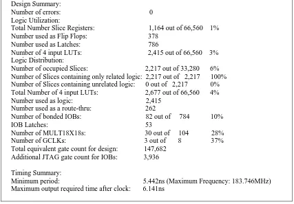
[image:3.612.80.518.405.700.2]Design Summary:
Number of errors: 0
Logic Utilization: Total Number Slice Registers: 1,164 out of 66,560 1%
Number used as Flip Flops: 378
Number used as Latches: 786
Number of 4 input LUTs: 2,415 out of 66,560 3%
Logic Distribution: Number of occupied Slices: 2,217 out of 33,280 6%
Number of Slices containing only related logic: 2,217 out of 2,217 100%
Number of Slices containing unrelated logic: 0 out of 2,217 0%
Total Number of 4 input LUTs: 2,677 out of 66,560 4%
Number used as logic: 2,415 Number used as a route-thru: 262
Number of bonded IOBs: 82 out of 784 10%
IOB Latches: 53
Number of MULT18X18s: 30 out of 104 28%
Number of GCLKs: 3 out of 8 37% Total equivalent gate count for design: 147,682
Additional JTAG gate count for IOBs: 3,936
Timing Summary:
[image:4.612.93.520.51.348.2]Minimum period: 5.442ns (Maximum Frequency: 183.746MHz) Maximum output required time after clock: 6.141ns
[image:4.612.47.554.389.528.2]Figure 3: Design Implementation summary of the good 31-bit length Ternary Pulse Compression sequence.
Figure 4: Behavioral simulation result of a good 23-bit Ternary Pulse compression sequence.
Figure 5: Behavioral simulation result of a good 31-bit Ternary Pulse compression sequence.
VII. CONCLUSION
In this paper we have proposed and implemented an efficient VLSI architecture for the identification of the good Ternary Pulse Compression sequences based on Meritfactor. The architecture implemented overcomes the drawbacks of non guaranteed convergence and slow convergence rate of the earlier optimization algorithmic based approaches for identifying the good ternary pulse compression sequences.
From the above results it is clear that this architecture is giving better meritfactor of 16.1333 for a 31-bit sequence length than the algorithmic based approach claimed in [8]. It was also observed that the proposed architecture is giving good meritfactor values for higher lengths. This shows the superiority of the architecture.
ACKNOWLEDGMENT
The authors are thankful to Dr.C.D.Naidu, Dr.P.Sudhakara Rao Professors of ECE Department of VNR VJIET for their constant technical support and encouragement. The authors are also thankful to the management of their respective organizations.
REFERENCES
[1] Golay M J E , “Sieves for low autocorrelation binary sequences”, IEEE Trans. Inf. Theory,1977 IT-23:43-51
[2] Barker R H, “Group synchronization of binary
digital systems”, In Communication theory (ed.) W Jackson (London: Butterworths),1953.
[3] Bernasconi J 1987, “Low autocorrelation binary sequences: statistical mechanics and configuration space analysis”, J. Phys. 48: 559-567
[4] De Groot C, Wurtz D, Hoffman K H 1992 “Low autocorrelation binary sequences: exact enumeration and optimization by evolutionary strategies” Optimization 23: 369-384
[5] Mohrir, P.S.: “Ternary Barker Codes”, Electron.Lett., 1974, 10, (22), pp.460-461
[6] Mohrir, P.S.: “Signal design (sequences with prescribed autocorrelation)”, Int. J. Electron., 1976, 41, (4), pp.381-398
[7] Moharir, P.s., Varma S.k., and VenkatRao, K: “Ternary Pulse Compression sequences”, J.IETE, 1985, 31, (2), pp.33-40
[8] Singh,R, Mohrir, P.S., and Maru, V.M: “Eugenic Algorithm-based search for ternary Pulse
compression Sequences”, J.IETE,1996,42, (1), pp. 11-19
[9] Moharir P S, Maru V M, Singh R, “S-K-H algorithm for signal design”, Electron. Lett. 1996 32:1648-1649
[10] Day R., Germon R., O'Neill B., “A Pulse compression Radar Signal Processor”, IEE Colloquim on DSP Chip's in Real Time
Instrumentation and Display Systems, 1997 4/1-4/5 [11] Day, R.H. Germon, R. O'Neill, B.C, “A real time digital signal processing solution for radar
pulse compression” ,IEE Colloquium on Digital Filters: An Enabling Technology,1998 6/1-6/5