Abstract—Liquid phase synthesis of one of the important fuel oxygenate, Ethyltert-butyl ether (ETBE) from ethanol andtert-butyl alcohol (TBA) has been studied in reactive distillation column (RDC) using ion exchange resin catalyst CT-145H. A packed RDC was used to generate experimental data. Effect of different key variables on reactant conversion and product purity in distillate, was investigated to find the optimum operating conditions for ETBE synthesis. The optimum conditions found were; reboiler duty of 375 Watts, molar feed ratio of reactants, 1:1.3 and reflux ratio of seven. Concentration profiles for each component along the length of the column at optimum conditions were also drawn.
Index Terms—ETBE synthesis, ion exchange resin catalyst, packed column, reactive distillation
1. INTRODUCTION
The ever-increasing numbers of gasoline driven vehicles have necessitated the requirement for an efficient fuel oxygenate as well as octane booster. Due to water solubility problem, MTBE is going to be banned in some parts of U.S; therefore, the alternative ethers are being worked out as fuel additives. Among the alternatives of MTBE, TAME and ETBE are considered next generation fuel oxygenates that fulfill the requirements of being efficient and environment friendly. ETBE has better blending as well as environmental characteristics like high blend octane rating of 111, low blend Ried vapor pressure of 27.8 kPa, low oxygen contents of 15.7 % and low water solubility of 23.7mg/l [1].
Mostly ETBE has been synthesized by exothermic reversible reaction between Isobutylene (IB) and ethanol (EtOH) [2]-[5], but the availability of IB is limited. It is only produced in refinery using catalytic and steam cracking operations. Therefore, alternative routes to synthesize ETBE are under substantial consideration. By far the most important substitute of IB istert-butyl alcohol (TBA) which is a by-product of propylene oxide
Manuscript received July 2, 2008. (Write the date on which you submitted your paper for review.) This work was supported by the Higher Education Commission (HEC) of Pakistan under indigenous scholarship scheme. M. Umar is with the University of Engineering and Technology, Lahore , 54890, Pakistan (corresponding author: phone: +92 345 4641847, fax: +92 42 9250202 e-mail:bazaidumar@ gmail.com).
A.R. Saleemi is with Department of Chemical Engineering, University of Engineering and Technology, Lahore , 54890, Pakistan as Professor and head of the Department. (e-mail: [email protected]).
N. Feroz is with Department of Chemical Engineering, University of Engineering and Technology, Lahore , 54890, Pakistan as Professor. S. Qaiser is with Department of Chemical Engineering, University of Engineering and Technology, Lahore , 54890, Pakistan as PhD student.
production in ARCO process. ETBE can be synthesized by direct reaction of TBA and EtOH in the presence of catalyst according to following reactions
O
H
ETBE
EtOH
TBA
2 (1)This main reaction is also accompanied by two side reactions.
O
H
IB
TBA
2 (2)ETBE
EtOH
IB
(3)Major side reaction is dehydration of TBA into IB and water (EQ. 2). As IB exist only in gaseous state at the atmospheric pressure experimental conditions, so backward reaction in equation 2 and reaction in equation 3 can safely be neglected. Reactive distillation (RD) is considered most suitable process for equilibrium limited chemical reactions such as esterification and etherification. There are number of works available for ETBE synthesis via RD using IB and EtOH on various catalysts [4]-[7]. There are fewer works available for ETBE synthesis using TBA and EtOH [3], [8]-[9]. There are even fewer research efforts available in open literature mentioning the ETBE synthesis via RD in packed column and those too emphasize on top and bottom product analysis for effect of different operating variables. Therefore, main objective of this study was to optimize the operating parameters for synthesis of ETBE in packed RD column using ion exchange resin catalyst CT-145H, found most suitable during batch kinetic and residue curve map studies [10]-[11]. Concentration profiles of each component along the length of the column are presented for each condition.
2. EXPERIMENTAL 2.1 Materials
Tert-butanol (>99%GLC), ethanol (98±1% GC), iso-propanol (99.8%GC) were purchased from local market manufactured by Merck Germany. ETBE (97% GC) was purchased from Fisher Chemicals UK. Purity of all these chemicals was verified by gas chromatography and after confirmation; these were used without further purification. Ion exchange resin catalyst CT-145H was provided by Purolite®International Limited and it was used after proper
pre-treatment.
2.2 Column and Packing
All the reactive distillation experiments were carried out in a packed glass column. QVF® glass columns of 0.0508 m
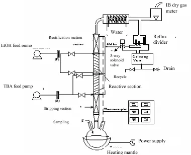
diameter and 0.3048 m length were assembled to erect the reactive distillation column. Schematic of the reactive distillation column is shown in Figure 1. Total height of the column was 1.22 m, in which stripping and rectification
Synthesis of Ethyl
tert-
Butyl Ether in Packed Reactive Distillation Column Using
Macroporous Ion Exchange Resin Catalyst
sections are of 0.3048 m length each while reactive section is 0.6096 m long. Reactive section of the column is kept longer as compared to stripping and rectification sections in order to have sufficient catalyst loading.
This column was erected on a four neck, 5.0-liter glass reaction vessel housed in a heating mantle (J.P Selecta Spain equipped with variable power input of 100 to 800 Watts). Stripping and rectification sections were packed with PRO-PAK®stainless steel distillation packing of 6x10⁻³m
diameter purchased from Sigma-Aldrich® Germany.
Schematic of the reactive distillation column assembly is shown in Figure 1.
Packing for reactive section was fabricated indigenously in shape of pockets, from 100-mesh stainless steel wire gauze corrugated at an angle of 45o. The pockets were filled with
pre-weighed quantity of catalyst CT-145H. These pockets were then ensemble to obtain a bundle like shape. Three bundles of approximately 0.1m height were packed in one piece of column. A timer operated solenoid valve controlled reflux to the column at desired ratio. The temperature measurements were made through K-type thermocouples at each section of the column. Reactants were fed to the column with pre calibrated, peristaltic pumps for each component.
2.3 Procedure
For a continuous experimental run, EtOH was fed at top of the reactive section and TBA was fed at the bottom of reactive section. The apt choice of feed location is very important as it ensures the high concentration of reactants in reactive zone. Both the feeding pumps were set at desired flow according to the molar feed ratio of reactants.
Figure 1 Schematic of experimental RDC set up
Reboiler was charged with known quantity of reactants according to the molar feed ratio and its duty fixed at specified value for a particular experimental run. Reflux was fed back to column at top of reactive section.
Experimental run was continued for four hours after attaining the steady state conditions. Top and bottom products were withdrawn continuously after the column reached steady state conditions. When steady state temperature profile in the column was attained, samples of approximately 1.0 ml quantity were collected from each sampling point located at all sections of the column and analyzed for their composition.
2.4 Sample Analysis
All samples were analyzed on gas chromatograph (Perkin-Elmer, Model Clarus 500), equipped with PORAPAK-Q column (80/100 mesh) of 2.0 meter length and 3.175x10⁻³m diameter using Thermal Conductivity Detector
[image:2.595.99.479.450.758.2](TCD). Injector and detector temperature were maintained isothermally at 458 K. Analyte sample volume taken was 1 micro litre and iso-propanol was used as internal standard. Helium gas of high purity (99.999%) was used as carrier gas at flow rate of 35 ml/min. Reference calibration sample was run daily before actual analysis to account for any change in instrumental response.
Fig.Reactive distillation
IB dry gas meter
Reflux divider
Heating mantle
Drain
Recycle
Reactive section
Stripping section
Power supply
Sampling
TBA feed pump EtOH feed pump
Rectification section Water
3. RESULTS AND DISCUSSIONS
The main objective of this study was to find out the optimum operating parameters for the synthesis of ETBE in reactive distillation column using macroporous ion exchange resin catalyst CT-145H. Effect of reboiler duty, molar feed ratio of reactants and reflux ratio was studied. The optimum column configurations must ensure maximum conversion of the reactants and yield of desired product. The optimum column configuration should also mitigate the requirement of subsequent separation step for the purification of desired product.
3.1 Effect of Reboiler Duty
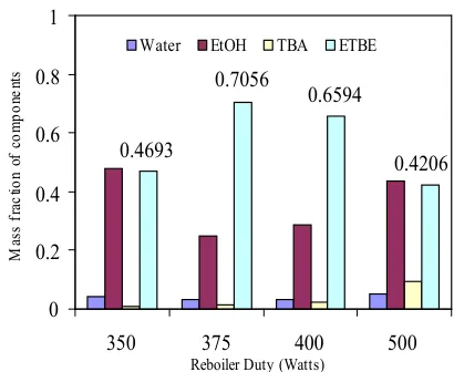
To find the effect of reboiler duty on ETBE synthesis in a continuous feed reactive distillation column, different levels of power input were studied. The selection of range of reboiler duty was based on the results obtained in batch reactive distillation experiments. The reboiler duties of 350, 375, 400 and 500 Watts were studied for their effect on distillate composition. For each of these experiments, the conditions maintained were, 1:2 molar feed ratio (MFR), reflux ratio of 5, EtOH fed at top of reactive section, TBA fed at bottom of reactive section and reflux was fed to the column at top of reactive section. Distillate product composition for each reboiler duty is shown in Figures 2. It is evident from the figure that reboiler duty of 375 Watts was found advantageous over others because it yielded higher concentration of desired product in the distillate. This reboiler duty (375W) is a bit higher as compared to that found optimum in batch reactive distillation studies (350 watts), which is plausible, as the fresh feed of reactants initially reduces the over all temperature of the column.
The temperature profile gradually returns to the steady state and the temperature at each position becomes constant. It was observed during experimentation that the initial distillate product was rich in desired product, and then there was gradual decrease in its concentration. This fact necessitates the removal of product from the system to shift the reaction equilibrium in forward direction. After introduction of the reflux, concentration of ETBE again started increasing in distillate. It is also to be noted that the distillate composition shown in the figure is average of three samples giving highest concentration of the desired product. Keeping in view the findings in these experiments, all the subsequent experiments were carried out at reboiler duty of 375 Watts.
[image:3.595.327.532.56.224.2]3.2 Effect of Molar Feed Ratio (MFR) of Reactants Various MFR’s were investigated in batch kinetic studies, RCM studies and in batch reactive distillation studies ranging from 1:1 to 1:8 (TBA: EtOH), [Umar et al., 2008(a, b)], In this section, the MFR’s found favorable in batch studies were explored to conclude that which MFR is optimum in continuous flow reactive distillation column. The MFR’s used in this study were 1:1.3, 1:1.5, 1: 1.7 and 1:2. Although the stoichiometric ratio of EtOH and TBA for ETBE synthesis reaction is 1:1, but ethanol is always fed in excess to get maximum conversion of the limiting reactants. The ratio of excess reactant (EtOH) greater than 2 was not found suitable
Figure 2
Effect of reboiler duty on distillate compositionat MFR of 1:2, reflux ratio 5
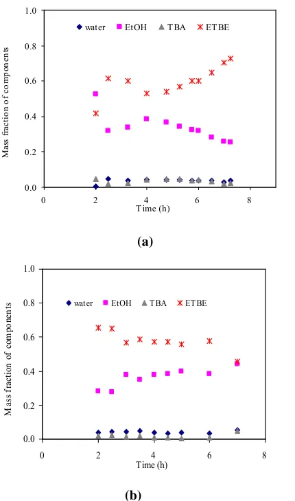
during batch studies. Therefore, the range of molar feed ratio used in this section was varied between 1:1.3 and 1:2 (TBA: EtOH). Concentration profile of distillate with respect to time for all molar feed ratios is presented in Figures 3 & 4.
These figures show that molar feed ratio of 1:1.3 yielded higher concentration of ETBE in distillate as compared to other MFR’s. Initially, ETBE concentration was more in distillate that decreased afterwards, which may be due to the scarcity of reactants for desired reaction.
After the introduction of reflux at 4thhour of experimental
run, concentration of ETBE started increasing in distillate. This is understandably due to the availability of more reactants for forward reaction. In all other cases of MFR’s, concentration of ETBE initially increased and then decreased or became constant. For MFR of 1:1.5 ETBE concentration at start was about 68 % in distillate, which gradually lowered down to 58 % where it became stable. The MFR’s of 1:1.7 and 1:2 did not produced good results, as more un-reacted ethanol was present in the distillate, which reduced the concentration of ETBE in the product distillate.
The reason for the high concentration of ETBE in distillate for MFR of 1:1.3 can be attributed to the presence of less quantity of ethanol in the reaction system. The excess ethanol is being utilized in the reaction due to reflux at the reactive section of the column. This statement is supported by the fact that the presence of TBA is very little in the distillate, which suggests that TBA is consumed in the reaction or the unconverted TBA is present in the reboiler.
It was also observed in these experiments that concentration of water was very little in distillate. Since water is least volatile component in the system, so it should not appear in the distillate. The presence of small quantity of water in distillate can be due to the formation of water-ethanol azeotropic mixture. More over quaternary azeotrope of all four components was also observed during the RCM experiments. Therefore, the presence of water in the distillate seems to be justified. Based on these experimental findings, MFR of 1:1.3 was considered optimum for ETBE synthesis from TBA and EtOH on ion exchange resin catalyst CT-145-H.
0.4693
0.7056
0.6594
0.4206
0 0.2 0.4 0.6 0.8 1
350 375 400 500
Reboiler Duty (Watts)
M
as
s
fr
ac
tio
n
of
co
m
po
ne
nt
s
(a)
[image:4.595.47.262.53.418.2](b)
Figure 3 Distillate composition profile for MFR of 1:1.3 (a)
and MFR 1:1.5 (b) at reboiler duty of 375 Watts and reflux ratio 5
3.3 Effect of Reflux Ratio
Reflux ratio plays a pivotal role in any distillation operation and its variations greatly affect the process performance. For reactive distillation system, effect of reflux ratio is even more important for enhanced yield and more conversion of the reactants to draw the reaction in forward direction. Excessive reflux needs too much reboiler duty and low reflux ratio results in less conversion as well as purity of the desired product. These limitations augment the need for a judicious choice of reflux ratio. In this particular study, the provision was made in experimental set up to get wide range of reflux ratios. Any desired reflux ratio can be set between 1 and 10. Total reflux option is also available in the experimental set up. Various reflux ratios were investigated for their effect on the distillate composition. The ratios selected for this study were 3, 4, 5, 6, 7, and 9. Lower than 3 and higher than 9 values were not found suitable for etherification reaction studies available in literature, therefore the range of reflux ratios implemented in this study were between 3 and 9.
It is to be mentioned that initially all the distillate was totally refluxed back to column until the column gained the steady state temperature profile, which took about 1 hour in most of the experiments.
(a)
[image:4.595.307.513.55.415.2](b)
Figure 4. Distillate composition profile for MFR of 1:1.7 (a)
and MFR 1:2 (b) at reboiler duty of 375 Watts and reflux ratio 5
Figure 5 Effect of reflux ratio on distillate composition
The experimental conditions were kept unchanged for reflux ratio experiments. These conditions were set at the values found optimum in preceding sections. Reboiler duty was fixed at 375 Watts, FMR at 1:1.3 (TBA: EtOH). Ethanol was fed at
0.0 0.2 0.4 0.6 0.8 1.0
0 2 4 6 8
Time (h) M as s fra ct io n of co m po ne nt s
water EtOH TBA ETBE
0.0 0.2 0.4 0.6 0.8 1.0
0 2 4 6 8
Time (h) M as sf ra ct io n of co m po ne nt
s water EtOH TBA ETBE
0.0 0.2 0.4 0.6 0.8 1.0
0 2 4 6 8
Time (h) M as s fr ac tio n of co m po ne nt s
water EtOH TBA ETBE
0.0 0.2 0.4 0.6 0.8 1.0
0 1 2 3 4 5 6 7
Time (h) M as sf ra ct io n of co m po ne nt
s water EtOH TBA ETBE
0.4251 0.4693
0.6594 0.6573 0.7262 0.6525
0.0 0.1 0.2 0.3 0.4 0.5 0.6 0.7 0.8 0.9 1.0
3 4 5 6 7 9
Reflux Ratio M as s Fr ac tio n of th ec om po ne nt s
[image:4.595.320.535.504.685.2]top of reactive section and TBA was fed at bottom of reactive section.
Reflux was fed back to column at top of reactive section. Distillate composition at various reflux ratios is shown in Figure 5. This figure shows that with the increase of reflux ratio, ETBE concentration increased in distillate until the reflux ratio of 7, where it reached 72.62 %. Further increase in reflux ratio resulted in reduction of ETBE in distillate. Mass fraction of the ETBE for each reflux ratio is indicated on bar graph. Increase in the ETBE concentration with reflux ratio may be due to the availability of more reactants for forward reaction until the equilibrium. Further increase in reflux ratio causes some unconverted ethanol going to the top product thereby decreasing the percentage of ETBE in the distillate
Concentration profile of the reaction system along the length of column is presented in Figure 6 at reflux ratio 7. This figure depicts that how the concentration of each component is changing as we move up in the column. It is evident from the figure that concentration of TBA and EtOH is maximum in reboiler and minimum in distillate. There is gradual increase in concentration of ETBE from bottom to middle of reactive section and then it rises rapidly at top of reactive section, which substantiates the effectiveness of catalyst.
[image:5.595.42.247.482.661.2]There is exponential increase in mass fraction of ETBE from top of reactive section to the reflux divider, which shows that most volatile component is being enriched in rectification section. This figure also shows that almost all the TBA has reacted with ethanol towards the middle of reactive section and there is very little decrease in concentration of TBA from middle of reactive section to the reflux divider. On the other hand, EtOH is being consumed very slowly. This suggests that stoichiometric amount of ethanol has reacted with TBA and its excess with the feed remains in the system.
Figure 6 Concentration profiles of components along the
length of Column at MFR of 1:1.3, Reboiler duty of 375Wattsand reflux ratio 7.
(RB=Reboiler, RxB=Bottom of reactive section,
RxM=Middle of reactive section, RxT= Top of
reactive section, RD= Reflux divider)
This also supports the argument for using molar feed ratios closer to 1:1, but for practical purposes, one reactant should be fed in excess to the limiting reactant. There is exponential increase in mass fraction of ETBE from top of reactive section to the reflux divider, which shows that most volatile component is being enriched in rectification section.
This figure also shows that almost all the TBA has reacted with ethanol towards the middle of reactive section and there is very little decrease in concentration of TBA from middle of reactive section to the reflux divider. On the other hand, EtOH is being consumed very slowly. This suggests that stoichiometric amount of ethanol has reacted with TBA and its excess with the feed remains in the system. This also supports the argument for using molar feed ratios closer to 1:1, but for practical purposes, one reactant should be fed in excess to the limiting reactant.
4. CONCLUSIONS
Synthesis of ETBE via RDC using ion exchange resin catalyst CT-145H was found favorable. Optimum operating conditions found experimentally for ETBE synthesis were molar feed ratio of reactants 1:1.3, reboiler duty of 375 Watts and reflux ratio of 7. The concentration of ETBE in distillate at optimum operation conditions was about 72 % and conversion of limiting reactant obtained was about 92 %.
REFERENCES
[1] F. Ancillotti and V. Fattore, “Oxygenate fuels: Market expansion and catalytic aspect of synthesis” Fuel Processing Technology, 57, (1998), pp. 163–194. [2] [2] C. Fite, M. Iborra, J Tejero, J. F. Izquierdo, and F.
Cunill, “Kinetics of the liquid-phase synthesis of ethyl tert-butyl ether(ETBE)”, Industrial and Engineering Chemistry Research, 33, (1994), pp 581-591.
[3] A. Quitain, H. Itoh, and S. Goto, “Reactive distillation for synthesizing Ethyltert-butyl ether from bio-ethanol”, Journal of Chemical Engineering Japan, 32, (1999), pp. 280-285.
[4] B. H Bisowarno, and M. O Tade,´ (2000), “Dynamic simulation of startup in ethyl tert-butyl ether reactive distillation with input multiplicity”, Industrial and Engineering Chemistry Research, 39, (2000), pp. 1950-1954
[5] M. O Tade,´ and Y.C Tian,., “Conversion inference for ETBE reactive distillation”, Separation and Purification Technology, 19, (2000), pp.85-91.
[6] M. G Sneesby, M. O Tade,´ R. Datta and T. N. Smith, “ETBE synthesis via reactive distillation. 1. steady-state simulation and design aspects”. Industrial and Engineering Chemistry Research, 36, (1997) pp. 1855-1869.
[7] B. H Bisowarno, and M. O Tade,´ (2002), “The Comparison of disturbance rejection properties of one-point control schemes for ETBE reactive distillation” Chemical Engineering Communications, Vol. 89(1), (2002), pp 85-100.
0
0.2
0.4
0.6
0.8
1
RB RxB RxM RxT RD
Segment of the Column
M
as
sf
ra
ct
io
n
of
th
e
co
m
po
ne
nt
[8] W. Kiatkittipong, S. Assabumrungrat, P. Praserthdam, and S. Goto, “A pervaporation membrane reactor for liquid phase synthesis of ethyl tert-butyl ether from tert-butyl alcohol and ethanol” Journal of Chemical Engineering Japan, Vol. 35, No. 6, (2002), pp. 547–556,
[9] S. Assabumrungrat, S. Wongwattanasate, D. Varong, V. Pavarajarn, P. Praserthdam, A. Arpornwichanop, and S. Goto, “Production of ethyl tert-butyl ether from tert-butyl alcohol and ethanol catalyzed byβ-zeolite in reactive distillation”, Korean Journal of Chemical Engineering, 21(6), (2004), pp. 1139-1146.
[10] M. Umar, A. R. Saleemi and S. Qaiser, , Synthesis of ethyltert-butyl ether withtert-butyl alcohol and ethanol on various ion exchange resin catalysts, Catalysis Communication., 9, (2008) pp. 721-727.
[11] M. Umar, A. R. Saleemi, M. Faheem and S. Qaiser, “Heterogeneous kinetics and residue curve map determination for ethyl tert-butyl ether synthesis via reactive distillation using ion exchange resin catalysts” Accepted in 18th European Symposium on Computer