LEABHARLANN CHOLAISTE NA TRIONOIDE, BAILE ATHA CLIATH TRINITY COLLEGE LIBRARY DUBLIN OUscoil Atha Cliath The University of Dublin
Terms and Conditions of Use of Digitised Theses from Trinity College Library Dublin Copyright statement
All material supplied by Trinity College Library is protected by copyright (under the Copyright and Related Rights Act, 2000 as amended) and other relevant Intellectual Property Rights. By accessing and using a Digitised Thesis from Trinity College Library you acknowledge that all Intellectual Property Rights in any Works supplied are the sole and exclusive property of the copyright and/or other I PR holder. Specific copyright holders may not be explicitly identified. Use of materials from other sources within a thesis should not be construed as a claim over them.
A non-exclusive, non-transferable licence is hereby granted to those using or reproducing, in whole or in part, the material for valid purposes, providing the copyright owners are acknowledged using the normal conventions. Where specific permission to use material is required, this is identified and such permission must be sought from the copyright holder or agency cited.
Liability statement
By using a Digitised Thesis, I accept that Trinity College Dublin bears no legal responsibility for the accuracy, legality or comprehensiveness of materials contained within the thesis, and that Trinity College Dublin accepts no liability for indirect, consequential, or incidental, damages or losses arising from use of the thesis for whatever reason. Information located in a thesis may be subject to specific use constraints, details of which may not be explicitly described. It is the responsibility of potential and actual users to be aware of such constraints and to abide by them. By making use of material from a digitised thesis, you accept these copyright and disclaimer provisions. Where it is brought to the attention of Trinity College Library that there may be a breach of copyright or other restraint, it is the policy to withdraw or take down access to a thesis while the issue is being resolved.
Access Agreement
By using a Digitised Thesis from Trinity College Library you are bound by the following Terms & Conditions. Please read them carefully.
Level of Detail Representations and Variation Methods for the
Rendering of Large Animated Crowds
Micheal Larkin
June 2, 2011
A thesis submitted to the University of Dublin, Trinity College in candidacy
^TRINITY COLLEGE^
2 0 JUL 2011
LIBRARY DUBLIN ^
Declaration
Abstract
The simulation of large crowds of characters is an important topic in the field of real time ren dering as games and movies strive for more realistic populated scenes. Displaying a city scene with a large crowd enhances the believability of a movie and immersive feeling of a game. What movies and games have in common is that the assets used to create the crowd, such as models, textures and animations must be generated by an artist. Time constraints mean that unique assets may not be created for every character in the environment, resulting in asset repetition throughout the crowd which must be disguised. Rendering crowds of larger sizes, detail and variety requires increased computation time. Though the creation of a fully populated city for non real-time applications such as movies may be done offline, with hours spent rendering each frame, time may be saved by approximating non-real time techniques for real time appli cations such as games. In a real time application frames must be drawn at a rate of at least 24 per second to maintain visual fluidity.
This thesis describes the research and development of a real-time rendering system capable of displaying a large crowd of characters with a high level of appearance and motion variation. The rendering system has been created to reflect the high level of behaviour complexity and animation variety of the crowd system for which it is built. A series of perceptual experiments have been performed to investigate the level of variation necessary to create the appearance of a perceptually varied crowd scene, evaluating both appearance and animation variation. Methods for the creation of this level of variation have been investigated, including colour, texture, geometry and accessory variation. The relative cost and effectiveness of each method has also been tested.
VI
Relevant Publications:
1. Clone Attack! Perception of Crowd Variety;
Rachel McDonnell, Micheal Larkin, Simon Dobbyn, Steven Collins and Carol O’Sullivan; ACM Transactions on Graphics (Siggraph) 2008
2. Eye-catching Crowds: Saliency based Selective Variation:
Rachel McDonnell, Micheal Larkin, Benjamin Hernandez, Isaac Rudomin and Carol O’Sullivan;
ACM Transactions on Graphics (Siggraph) 2009
3. Topological Culling and Unified Levels-Of-Detail for Highly Varied Controllable Crowds: Micheal Larkin, Sebastien Paris, Simon Dobbyn and Carol O’Sullivan;
Workshop on Crowd Simulation 2010
4. Every last detail: density based level of detail control for crowd rendering (Poster): Micheal Larkin, Sebastien Paris, Simon Dobbyn and Carol O’Sullivan;
ACM SIGGRAPH Symposium on Interactive 3D Graphics and Games 2010
5. Meshacre: Rendering an animated crowd part by part: Micheal Larkin, Cormac O’Brien and Carol O’Sullivan;
6. Perception of Simplification Artifacts for Animated Characters: Micheal Larkin and Carol O’Sullivan;
Acknowledgements
To begin, I’d like to thank my supervisor Carol O’Sullivan for her invaluable input and advice that made this work possible.
Thanks also to my friends in GV2, especially those who I worked on papers with and were around at deadline time or for the estimated 880 lunches that we’ve eaten since I started this.
Cheers to my friends in The Binge and in Trinity, for sitting through my many experiments and keeping me entertained over the past few years, you deserve those book tokens.
Finally, I owe the most gratitude to my parents Mary and Tom, for supporting and encour aging me through the past years no matter what I have undertaken. Thank you for absolutely everything.
Contents
List of Figures xi
Chapter i Introduction i
1.1 Methodology... 3
1.1.1 Software Systems... 3
1.1.2 Perceptual Experimentation... 3
1.2 Scope... 4
1.3 Contributions... 5
1.4 Summary of Chapters... 7
Chapter 2 Background and Related Work 9 2.1 Character Rendering... 10
2.1.1 Character Mesh... 10
2.1.2 Texture mapping... 11
2.1.3 Shading... 11
2.1.4 Skinning... 12
2.1.5 Photorealistic Skin Rendering... 12
2.2 Rendering Acceleration... 13
2.2.1 Culling ... 13
2.2.2 Geometric Level of Detail ... 15
2.2.3 Sample Based Rendering... 20
2.2.4 Perceptually Based Simplification... 24
2.2.5 Level of Detail Selection ... 25
2.2.6 Exploiting Graphics Hardware... 26
2.3 Crowd Variety... 27
2.3.1 Geometry... 27
2.3.2 Colour... 28
2.3.3 Texture ... 29
CONTENTS IX
2.4.1 Low Level Perception... 29
2.4.2 Rendering Acceleration... 30
2.4.3 Rendering and Animation Quality... 31
2.4.4 Statistical Models... 32
2.5 Conclusion... 32
Chapter 3 Creating Variation 33 3.1 Introduction... 33
3.2 Appearance and Motion Variation... 34
3.2.1 Assets and Framework... 35
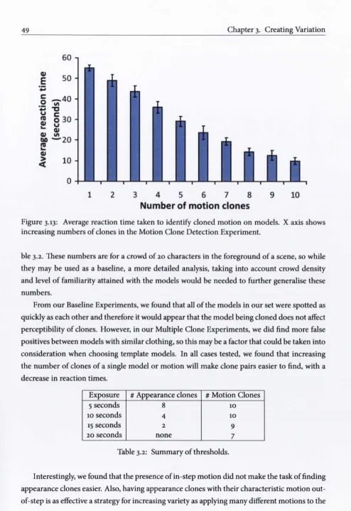
3.2.2 Baseline Experiments... 38
3.2.3 Multiple Clone Experiments... 42
3.2.4 Conclusions ... 48
3.3 Variation Methods and Optimisations... 50
3.3.1 Assets and Framework... 51
3.3.2 Appearance Experiment... 53
3.3.3 Selective Variation Experiments... 62
3.3.4 Testing Crowd Variation... 66
3.3.5 Performance and Conclusions... 68
3.4 Discussion... 70
Chapter 4 Level of Detail 72 4.1 Introduction... 72
4.2 Level of Detail Selection... 74
4.2.1 Topological environment culling... 74
4.2.2 Unified Levels-Of-Detail... 77
4.2.3 Complexity and Scalability... 81
4.2.4 Conclusion... 83
4.3 Density based LOD control... 83
4.3.1 Resource Distribution... 84
4.3.2 Complexity and Conclusions ... 86
4.4 Simplification Artefacts... 89
4.4.1 Artefact Separation... 89
4.4.2 Framework... 91
4.4.3 Artefact Experiment... 91
4.4.4 Silhouette Detection... 95
4.4.5 LOD Saliency Prediction... 96
CONTENTS
4.5 Discussion... 100
Chapter 5 Level Of Detail Crowd Rendering 102 5.1 Introduction... 102
5.2 Point Based Rendering... 103
5.2.1 Point Based Progressive Mesh... 104
5.2.2 Point Cloud Generation ... 105
5.3 The Meshacre Rendering system... 106
5.4 Overview... 107
5.4.1 Motivation... 109
5.5 Mesh Generation... no 5.6 Roll Invariant Quaternion Lookup... 113
5.7 Crowd Rendering... 116
5.8 Evaluation... 117
5.9 Conclusion... 120
5.9.1 Discussion ... 121
Chapter 6 Conclusions and Future Work 122 6.1 Summary of Contributions ... 122
6.2 Limitations... 125
6.3 Future Work... 125
6.3.1 Enhancement of the Meshacre rendering system... 125
6.3.2 LOD Metric... 126
Appendix A 127 A.i Experiment Details... 127
A.2 Experiment Data ... 127
A.2.1 Clone Attacks Experiment Tables... 127
A.2.2 Selective Variation Experiment Tables... 133
A.2.3 Artefact Experiment Tables ... 140
A. 3 Information Sheet Template... 143
Appendix B 146 B. i Occulsion Determination Pseudocode... 146
B.2 Mesh Generation Pseudocode... 147
List of Figures
1.1 The Metropolis System... i 1.2 Assassins Creed... 2 1.3 Crowd rendering in Fifa 09... 3
2.1 A: Character represented by mesh of polygons. B: Texture mapped polygonal mesh. C: Textured and shaded character. D: Character with skin shader [dLo7]. 11 2.2 Top row: Mesh representations with high and low levels of detail. Bottom row:
Same meshes with texture applied... 16 2.3 Left: An impostor as seen from the camera and as seen from an alternative
viewpoint. Right: A point based representation at various distances... 21 2.4 A sample of colour modulation applied to a cloned model... 27
3.1 Texture and accessory variation... 34 3.2 (a) Texture map and Alpha map images, (b) Example of the HSV shader being
used to create 12 outfits... 36 3.3 Examples of crowds where the foreground characters are most visible [Thao6]. 36 3.4 Example scene from the multiple clone experiments... 37 3.5 Example of the exact clone condition in the Appearance Baseline Experiment. 38 3.6 Interaction between Axis and Distance. Graph shows average reaction time
taken to identify a pair of clones in different positions. Standard error calcu lated as square root of variance / count... 40 3.7 Example of final positioning in the Motion Baseline Experiment... 41 3.8 Reaction times for static appearance clones Ac (forward facing). Average re
sponse time to identify clones shown for increasing numbers of clones... 44 3.9 Average reaction time taken to identify cloned models in five different orien
tations. Reaction times averaged over the 10 number of clone levels... 45 3.10 Average reaction time taken to identify increasing numbers of cloned models,
Xll LIST OF FIGURES
3.12 Example of a crowd from Me... 48
3.13 Average reaction time taken to identify cloned motion on models. X axis shows increasing numbers of clones in the Motion Clone Detection Experiment.... 49
3.14 Example scene from front orientation condition... 50
3.15 Mesh split into 14 different regions... 51
3.16 Participant in the motion saliency experiment... 52
3.17 Example scene from side orientation condition... 52
3.18 Example scene from back orientation condition... 53
3.19 Y axis shows Percentage of “clones present” responses. X axis shows number of clones present on screen... 55
3.20 Fixation duration main effect of body part over all orientations. Y axis shows average fixation duration in milliseconds. Labels: L, R, 1 and 2 represent Left, Right, Upper and Lower respectively... 56
3.21 Interaction between orientation and body part showing the change in fixation duration for the head and torso depending on character orientation... 57
3.22 First fixation main effect of body part over all orientations. Y axis shows the average number of first fixations when a scene is displayed. X axis corresponds to each body part tested... 58
3.23 No main effect of the presence or absence of motion. Y axis shows the average fixation duration per body part during the “clones present” task. X axis shows each body part, with and without motion... 59
3.24 Example scene from the Motion Experiment... 60
3.25 Main effect of body part in Motion Experiment. Y axis shows fixation duration during the “clones present” task. Labels: L, R, 1 and 2 represent Left, Right, Upper and Lower respectively... 61
3.26 Main effect of variation type. Y axis shows average reaction time, measured in seconds for the clone identification task with different variation schemes employed... 62
3.27 Facial texture variation... 63
3.28 Main effect of variation type. Y axis shows average reaction time taken to iden tify a pair of clones. Different variation types are displayed along the X axis. . 64
LIST OF FIGURES xiii
3.31 The character on the left was most often confused with the two characters to his right... 67 3.32 Back and front orientation reaction times. Y axis shows average reaction time
taken to identify a pair of clones. Different variation/orientation combinations are displayed along the X axis... 68 3.33 (left) crowd using 6 template models with colour variation only, (right) crowd
using 2 template models with colour, texture and accessory variation. Y axis shows user responses, X axis shows variation combinations... 68 3.34 Results from Crowd Experiment. C = colour variety alone, C+T = colour +
texture variety, C+T+A = colour + texture + accessories... 69 3.35 Texture memory consumption reduction for selective texture variation based
on one character cloned... 70
4.1 Input triangulated environment with edge semantics: “building” in red, “park” in green... 75 4.2 Graphical culled representation: only green areas are visible. CPos is Camera
Position... 76 4.3 Culling example. Solid edges are occluding, dotted are not; purple edges are
not processed; green areas are visible. C is Camera Position... 77 4.4 Culling DFS algorithm steps... 77 4.5 Culling example in our test environment (102 angle quadrants). Only red edges
are considered occluding, other ones being simply traversed by the algorithm. The green areas cover visible parts inside the camera FOV, the red areas being for the clipped parts... 78 4.6 Input LODs unification. On the left, 3 input LODs (A, B, C); on the right, the
corresponding unified LOD... 78 4.7 Per quadrant culled LOD computation... 79 4.8 Three methods to retrieve a ULOD: direct, smoothed, anticipated. The covered
angles and corresponding distances are shown in green for each method. ... 80
4.9 ULOD calculation times for a 30 second walkthrough. X axis shows timesteps, Y axis shows time taken in milliseconds to calculate ULOD sets for the currently visible en vironment... 81
4.10 ULOD extraction times for a 30 second walkthrough. X axis shows timesteps, Y axis shows time taken in milliseconds to extract LOD and occlusion data for all agents. . . 82
XIV LIST OF FIGURES
4.12 Characterisation of the density in each triangle after triangulation, white for near null density; gradient from green to red for low to high densities. The
high per-character accuracy achieved by the Delaunay trianguation is clear. . . 85
4.13 Resource distribution according to density: the bigger the radius of an agent, the larger the number of used primitives... 87
4.14 Timings for Delaunay Triangulation. Y axis shows time taken to perform cal culation. X axis shows increasing number of agents... 88
4.15 Texture, Silhouette and Lighting Simplifications... 90
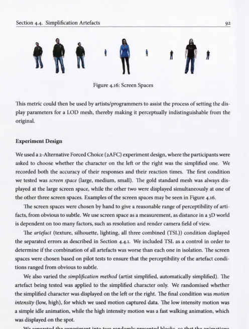
4.16 Screen Spaces ... 92
4.17 Main effect of Artefact. Y axis shows average percentage of correct responses for the “choose the simplified mesh” task. X axis shows artefacts displayed. TLS is texure, lighting and silhouette together... 93
4.18 Interaction between artefact and screen space. Y axis shows percentage of cor rect responses when tasked with identifying simplified meshes. X axis shows decreasing screen space... 94
4.19 Main effect of screen space. Y axis shows average percentage of correct re sponses for the “identify the simplified mesh” task. X axis shows decreasing screen space... 97
4.20 Plot of observed PSE distances with standard error bars and distances com puted by our metric. Y axis shows distance in world units (we use meters) at which differences in models were judged to be imperceptible. Lo = Artist simplified. Li = Automatically simplified... 99
5.1 Crowd Scene, point cloud for background characters... 105
5.2 Mesh split into chosen (B)ody parts... 108
5.3 Head body part in a number of (O)rientations... 108
5.4 (L)evels Of Detail for a Body Part * Orientation combination... 109
5.5 An entire character as represented by a number of B’^O^L combinations. . . . 109
5.6 Ten separate body parts used to create our renderable mesh... 111
5.7 Evenly distributed points on the surface of a sphere: 20 on the left, 40 on the right... 112
5.8 A series of angles for the head body part baked into position at two levels of detail... 112
5.9 Quaternion Space Visualisation... 115
5.10 EPS values of our test case walkthrough with 500 characters... 117
5.11 EPS values of our test case walkthrough with 2000 characters... 118
LIST OF FIGURES XV 5.13 Number of entities visible during our test walkthrough... 119 5.14 Comparison of memory consumption between three representations. DXT
Chapter i
Introduction
Everyone who got where he is had to begin where he was.
-Robert Louis Stevenson, Novelist (1850 -1894)
- * 1 K ■■ ' i ' * ' , T. 1 ^ ^ t ■ ■ ^ ■ f
r '* '*'^4 u’ J ■ n "'‘i
f-Figure 1.1: The Metropolis System.
A
s MOVIES AND GAMES Strive to increase realism, generating crowds of natural looking and authentically animated characters has become an active area of re search. However, rendering such large crowds remains computationally expen sive. Methods have been developed to render photorealistic crowds but the com
putational intensity of such techniques means that their use is not feasible in the real-time rendering domain. Displaying these characters in real time for computer games or interac
Section
This thesis investigates the creation and rendering of crowds of animated characters. It is therefore necessary to discuss the meaning of the term “crowd”. For our purposes, a crowd should be interpreted as a large number of people, some in groups, some alone, engaged in seperate activities. As we are dealing with large open spaces, a crowd develops when the num ber of visible groups and individuals number in the thousands.
Games such as the Grand Theft Auto series are based in cities which can be rendered with an extremely high detail due to their static nature. The lack of an appropriately sized crowd in these games detracts from the realism of the simulation. The provision of a realistically rendered large and varied crowd would be an extremely significant contribution to the genre.
Figure 1.2: Assassins Creed.
State of the art games such as Assassins Creed (See Figure 1.2) exhibit a complex animation system, implementing inverse kinematics as a layer for more detailed animations. The realism is somewhat reduced by the repetition in the behaviour at lower levels of detail. Though the game is rendered with full polygonal meshes, repetition in animation becomes visible in scenes of larger crowds [BTM^oS]. Methods to increase the variety in behaviour and animation require the development of a rendering system capable of reproducing these aspects in real time.
The rendering of large crowds in games remains in its infancy; e.g.. The image based render ing system as seen in games with stadium crowds such as Fifa 2010 exhibits very little animation variation (Figure 1.3), with only very basic colour and texture variation. This may be acceptable in stadium crowds where repetition in animation and texture is more common, but would be unacceptable in a crowd simulation where the expectation for variation is much higher.
Chapter i. Introduction
unit. This makes polygonal meshes more attractive as a rendering method than impostors, though impostors are still being employed for large crowds in real time games at the expense of variety.
' V - „ It/ ' i\ \ -r't r ^ l' ■ * »’»- '■ ^ ; j,' y y r
■> '‘Vrc. / ■ ■* , \ '
A* t. ^
Figure 1.3: Crowd rendering in Fifa 09.
1.1 Methodology
1.1.1 Software Systems
The Metropolis Project is a multidisciplinary project with the aim of developing a complete crowd system that can display thousands of realistic characters in real time. We have designed a crowd containing individuals, conversing groups and dynamic groups, along with an animation system capable of matching this level of variation in behaviour. A rendering system that can display thousands of characters at this level of complexity on commodity hardware has also been developed. The Metropolis System also implements other important factors, such realistic audio adjusted according to the environment and the crowds surroundings, traffic noise and traffic behaviour and rendering. The system has been developed with input from disciplines outside of computer graphics, such as neuroscience, where the system may be used to perform perceptual experimentation, the results of which are used to further develop and enhance the system. A screenshot of the system may be seen in Figure 1.1. The Metropolis area covers 0.5 square kilometres, with 10 kilometres of walkable streets accessible by our characters.
1.1.2 Perceptual Experimentation
Section 1.2. Scope
• Analysis Of VAriance (ANOVA). This is a statistical test of whether or not the means of several sets of data are equal.
• Post-Hoc analysis using Newman-Keuls pairwise comparison across means. This test makes a comparison of group means after ANOVA has rejected the null hypothesis. It can be used to find significant differences between data sets in more detail.
• Ogive. An Ogive is a graph showing the curve of a cumulative distribution function, describing the probability that a variable X will be found at a point less than or equal to a point under the curve.
• Just-Noticeable Difference. This is defined as the smallest detectable difference between a gold standard and a secondary level of a particular stimulus.
• Point of Subjective Equality. This is the point at which a subject will perceive two different stimuli to be indistinguishable.
Further detail on psychological statistics may be found in [Cohoi].
1.2 Scope
Chapter i. Introduction
1.3 Contributions
We have developed a rendering system capable of a high level of animation and visual variation, with many optimisations allowing the rendering of thousands of unique characters in real time. Development of this rendering system required investigation into the levels of variety and detail necessary to ensure a realistically rendered crowd. To create a truly varied crowd would require an individual model for each and every character in the scene, impossible for a large crowd scene due to both the time required for an artist to create all the models, and the computational storage and power required to handle assets of such a scale. We are limited by the amount of artist resources that can be created, so methods are required to vary the appearance of all these resources while maintaining realism.
• We begin by performing a series of perceptual experiments designed to determine what factors contribute most to creating the illusion of a varied crowd, and how can we best exploit these factors with a limited amount of resources. We investigate the relative ef fectiveness of appearance variation, motion variation, along with methods for creating this variation, such as texture variation, colour variation, geometry variation and using alter native methods such as accessories to disguise the use of repeated characters in a scene. This variation requires computational power, so our perceptual experiments are designed to reveal the limits of what we need to create the illusion of a varied crowd. We have dis covered how much appearance and motion variation is necessary, what we should best spend our effort varying, and how to optimise this variation as much as possible to save computational power, allowing us to scale our crowd up as much as possible. ’ ^
Level of detail simplifications must be employed to make efficient use of our rendering hard ware. These simplifications may be automatically generated or created by an artist. In both cases it is advantageous to know what artefacts introduced by these simplifications are the most salient.
Our second set of experiments was designed to discover the factors most important when simplifying a crowd. We have used perceptual experimentation to investigate the relative saliency of artefacts introduced during the simplification process. A novel method for in dividually rendering these artefacts has been developed and a series of perceptual exper iments employing this method have been performed. The knowledge gained from these experiments allow us to assist the artist or a simplification method in creating these sim plified versions without major artefacts. It also provides the basis for a method to assist
'Clone Attack! Perception of Crowd Variety
Section 1.3. Contributions
programmers in determining what distance these simplified models could be impercep tibly placed in a scene. In a large crowd for either games or movies, this would save time on what would be a tedious, time consuming process.
Typically, the most basic method of choosing whether to render a simplified version of a char acter is determined based on the distance of that character from the camera. This leaves huge scope for optimisation, such as character occlusion.
• We have created a selection method that may be used to very quickly return a level of detail evaluation based on a number of factors, such as distance from the camera, and occlusion data, irrespective of field of view. This unified level of detail value can be re ported for any of the Metropolis sub-systems, allowing us to vary behaviour, animation and rendering detail at a very high granularity. We have also developed a method to aug ment our rendering level of detail choice based on the crowd density in the area around each agent. This allows us to tailor the detail used to display each character not only by the distance from the camera but also by the level of occlusion provided by the crowd in its proximity. ^ ■*
Our level of detail selection system can tell us the distance at which we should display our realistically behaving, animated, and varied characters. Our final requirement is a rendering system capable of displaying this level of variety and handling this level of detail granularity while rendering a crowd of characters to a massive scale. This is achieved with the development of a rendering system optimising the lower levels of detail, using traditional mesh rendering methods for the higher levels of detail. We have investigated the applicability of the use of points as a fast rendering primitive, and outlined the development of a point based progressive mesh that can be rendered very quickly and be easily altered by our density evaluation. 5
• We describe a new mesh based rendering method that implements all the factors desir able for a large crowd rendering system. The “Meshacre” rendering method has been developed to provide effective animation compression, layering and reuse, allowing a crowd to be rendered at high speed with a high level of behaviour and animation vari ety. This method provides a high level of detail granularity, allowing us to take advantage of our level of detail selection method and our crowd density calculations to alter levels of detail down to individual parts of a single character, making efficient use of our rendering hardware. We use graphics hardware acceleration to perform highly parallel search tasks integral to our rendering method on the GPU, freeing the CPU for tasks like crowd be haviour and animation. Our rendering system is also capable of displaying the high level
’Topological Culling and Unified Levels-Of-Detail for Highly Varied Controllable Crowds “'Perception of Simplification Artifacts for Animated Characters
Chapter 1. Introduction
of appearance variation that our perceptual experiments have determined to he neces sary.
1.4 Summary of Chapters
The remainder of this thesis is structured as follows:
• Chapter 2 provides a detailed overview of the existing work related to what we have de veloped. It is split into three sections, dealing with perception, variation and level of detail rendering methods.
• Chapter 3 describes our perceptual experiments developed to determine the level of va riety necessary to create the impression of a hetrogeneous crowd. It also details the ex periments used to determine the relative effectiveness of alternative types of variation.
• Chapter 4 details our unified level of detail selection method, along with our method for adjusting the level of detail at which a character is displayed based on the crowd density around that character. We also describe our perceptual experiments used to influence the level of detail generation and selection based on the perceptibility of artefacts introduced during simplification.
• Chapter 5 describes the results of our investigation into point based rendering. We also detail our preferred rendering method; Meshacre, from model generation and animation compression to our optimisations used to render a massive crowd in real time.
• We conclude in Chapter 6 with a discussion on what future developments we plan to implement to develop our work and further improve our crowd rendering system.
Chapter 2
Background and Related Work
An original idea. That can’t be too hard. The library must be full of them. -Stephen Fry, Writer and Comedian (1957 -)
P
HOTOREALISTIC computcr generated crowds are a common occurrence in movies, whereas their presence in real time computer games is less common, due to the increase in both processing power necessary to render such large crowds and the time taken to generate the assets needed to create such a large varied crowd. In
this chapter we present a review of the research and techniques that have been used to develop more realistic crowds at a larger scale.
• We first introduce the basic techniques used to draw, light, shade and deform a character, as it is these techniques that we must build on to draw a larger crowd. We then discuss techniques used to increase the speed at which a character may be drawn and so increase the number of characters that we can draw per frame. These include alternative character representations, level of detail techniques, and methods for removing unnecessary detail from the rendering of the scene.
• Next, we discuss methods by which repetition, introduced by the reuse of art assets in a crowd may be hidden. This is of major importance to the scaling up of crowd sizes. This includes alteration of colour, texture detail, variance in motion and the addition of accessories to alter the appearance of a character.
Section 2.1. Character Rendering 10
in rendered scenes. Understanding the effects of level of detail simplifications or varia tion alterations will allow us to better design a rendering system influenced by human perception.
2.1 Character Rendering
The presence of realistic crowds in computer games and applications requiring real-time up dates is rare. When such scenes are rendered for movies, hours can be spent rendering each and every frame of the scene, using techniques such as photon mapping, radiosity, subsurface scattering and ray tracing as in Dutre et al. [DBB03]. However not only realistic light rendering is needed, dynamic effects such as hair and cloth movement are also an important considera tion. In real time applications, a frame rate of at least 24 frames per second must be maintained to achieve any sense of fluidity. Ideally, even higher frame rates must be achieved, as a higher refresh rate reduces latency and increases the sense of “presence” for the viewer [MRWBJ03]. This limits the amount of computation that can be done per frame. The rendering of crowds of animated characters is computationally expensive; maintaining this real time frame rate means that the development of optimisations is of particular importance in this field. Many advances have taken place since the development of 3d graphics but despite the continuing increase in computing power available, the demand for ever more realistic scenes ensures that these re sources are quickly exhausted. The global illumination techniques available for use in the film industry remain too computationally intensive for real time applications, so developers have come up with a number of approximations of these physically based methods, making them candidates for use in real time applications.
2.1.1 Character Mesh
11 Chapter 2. Background and Related Work
Figure 2.1: A: Character represented by mesh of polygons. B: Texture mapped polygonal mesh. C: Textured and shaded character. D: Character with skin shader [dLoy].
2.1.2 Texture mapping
Texture mapping, introduced by Catmull [Cat74] is a method for adding detail to a surface, which in our case is a polygonal mesh representing a character. In the case of human characters, these textures are generally photographs of the character that has been modelled, or designer drawn textures in the case of less realistic characters. The texture is loaded into memory as an image, with each vertex in the mesh having a texture coordinate corresponding to a part of the image in two or three dimensions, thus allowing the image to be applied to the appropriate part of the mesh. See Figure 2.1.
2.1.3 Shading
Section 2.1. Character Rendering 12
2.1.4 Skinning
Skin deformation based on an underlying skeleton is a common method used to animate polyg onal meshes. Linear blend skinning (LBS) is the most common algorithm used to deform the mesh, because of its simplicity and speed. LBS suffers from a number of artefacts, such as col lapsing joints, sometimes called the “candy wrapper” effect. A number of methods have been developed to address this problem, such as spherical blend skinning [KZ05], which addresses the collapsing effects by interpolating transformations instead of transformed vertex positions. Interpolating transformations results in vertices being translated along a curve rather than a straight line, thus creating a more plausible deformation. Kavan’s work on skinning using dual quaternions [KCZO07] eliminates skinning artefacts by retaining volume during transforma tions and eliminating the candy wrapper effect. Basic cloth deformation may be achieved by the use of skeletal deformation, more complex methods are out of the scope of this work.
2.1.5 Photorealistic Skin Rendering
As a character takes up more space on the screen, we need an enhanced, physically based ren dering technique to ensure that the character’s appearance is as realistic as possible. Lighting models such as Phong and Cook-Torrance [CT81] perform well, but at short distances other properties of light’s interaction become prevalent. Skin consists of multiple layers and the inter action with light and these layers give skin its soft appearance. Light reflecting off a non-opaque material may enter the material, reflect multiple times underneath the surface of that material, thus causing the material to affect the colour of the light. Some of this light will eventually escape the material at a different spot than where it entered.
This was approximated by Beeson and Bjorke [BB04]. Their method involves rendering the lighting of the model in texture space, i.e., directly onto the texture, but using the physical data of the mesh to calculate the lighting. This texture is then Gaussian blurred a number of times to mimic the light scattering softly under the surface. These blurs are added back together in different ratios based on the work of [AP81], who measured the scattering of light under the skin. Light of different wavelengths scatters differently under different surfaces, so each of red, green and blue are added back in certain proportions, thus mimicking the scattering of light in layers of skin in real-time.
13 Chapter 2. Background and Related Work
with each layer and create a more realistic representation of the underlying details in human skin. These images are not rendered in real time, but the results may be used to alter scatter ing profiles in other real-time solutions. Jimenez et al. [JWSGio] model subsurface scattering effects and the passing of light through thin areas of the skin such as the ear achieving a real istic rendering for one face model in real time. Jiminez et al. [JSB+10] adjust facial colour in real time based on skin deformation and emotion. These methods are computationally expen sive, so may only be applied to a small number of characters. They are therefore not usable for crowds as a whole, but apply only to foreground characters, where the subtle effects may be noticed.
2.2 Rendering Acceleration
As previously stated, polygonal meshes are the most commonly used representation for objects in a scene. The requirement for interactivity in applications such as games imposes a limit on the number of polygons that may be rendered by the graphics hardware, in order to achieve real-time frame rates. As more characters are rendered in a crowd scene, the polygon count increases rapidly. A number of approaches may be taken to decrease the number of polygons that are rendered per frame, without detracting from the required level of visual complexity and realism in the scene.
2.2.1 Culling
Section 2.2. Rendering Acceleration 14
to cell visibility. The visibility result obtained by this From-Region method remains valid while the camera moves inside the current cell, but its computation is only efficient for axis aligned architectural models, and hardly applicable for large scale outdoor environments.
Bittner et al. [BHS98] propose a From-Point model, whose results are valid only for a given viewpoint. This approach proves to be more accurate than the From-Region method, but at the expense of the computational cost. Zhang et al. [ZMHHI97] present hierarchical occlu sion maps, a From-Point method for visibility culling based on rendering a set of occluders to a texture from which lower detail occlusion maps are created. This approach improves the performance, but is prone to errors due to the texture discretisation. Andiijar et al. [ASVNoo] introduce a method for generation of LOD occluders, which are a series of automatically gen erated, simplified versions of a mesh that can be used for occlusion tests. More aggressive levels of simplification are likely to introduce errors to the rendered image.
Most techniques are conservative, i.e., they overestimate the set of visible candidates to ensure a correctly rendered image. The Prioritised-Layer Projection (PLP) algorithm [KSoo] is an approximate rendering technique that computes a partially correct image. Klosowski and Silva [KSoi] improve upon this method by using image space techniques in order to find the remaining visible primitives. Bittner and Havran [BHoi] make use of the temporal and spatial coherence of visibility results. This allows them to avoid visibility tests on regions that are expected to remain visible, reducing the number of necessary tests per frame. Nirenstein et al. [NBG02] present an exact method, where 3D polygons and lines connecting them are represented in a 5D space, resulting in a structure that can then be queried from a region in space to determine what polygons are visible. Since the algorithm returns an exact solution, it is slower than conservative algorithms.
Bittner et al. [BHS98] describe a From-Point visibility determination method. This method is based on a binary space partition that generates occlusion volumes with temporal coherence. This conservative method has been shown to on average halve the rendering times on tested scenes. Wonka and Schmalstieg [WS99] detail a 2.5D method, where visibilty and height values are stored in a bitmap. These bitmaps are generated by casting shadow frusta from the camera viewpoint. Visibility at points in the environment can then be determined by querying this bitmap.
15 Chapter 2. Background and Related Work
an extension to outdoor scenes in 3D. The partitioning tree for the cells and portals method is automatically generated and designed to deal with walls of an arbitrary orientation. Recalcula tion of visibilty due to alterations in the environment may be done quickly, as the recalculation is dependent only on cells in the vicinity of the alteration.
Hillesland et al. [HSLM02] present an implementation of an algorithm using Hardware Occlusion Queries which determine the number of pixels rendered to by an object. This model is improved upon by Sekulic [Seko4]. Inaccurate query results based on bounding boxes are avoided by performing the Hardware Occlusion Query at object level and delaying checking the result until the following frame. This is an aggressive culling method that cannot guarantee a hole free rendering. The visible errors associated with aggressive methods often increase with decreasing frame rate. The use of the Hardware Occlusion Query was optimised by Bittner et al. [BWPP04]. Their method approximately subdivides the scene and reuses query results over as many frames as possible so as to minimize the number of queries issued. This offers a practical approach to the use of Occlusion Queries on arbitrary scenes. A major drawback of these Hard ware Occlusion Query methods is that they are hardly scalable as their complexity depends on the entire rendered environment. Batching and minimising state changes and draw calls, as in [MBW08] increases the scalability of Hardware Occlusion Querys dramatically. Guthe et al. [GBK06] further optimise the use of the Hardware Occlusion Query by employing a statistical model to control the issuing of queries. Staneker et al. [SBW06] reduce the number of redun dant Hardware Occlusion Queries issued by discovering areas in the scene that are unlikely to be occluded and neglecting to test these areas. Hardware Occlusion Queries are less effective for crowd scenes, due to the cost of maintaining spatial heirarchies and the large number of occlusion tests needed for smaller dynamic objects.
2.2.2 Geometric Level of Detail
Polygonal models offer great scope for optimisation through the use of various LOD tech niques. The basic aim of level of detail is to make more efficient use of the resources available to render an object while maintaining that objects fidelity to the highest possible degree. This is achieved by decreasing its complexity as it takes up relatively less screen space. A concise overview of level of detail techniques may be found in [LWC^02].
Section 2.2. Rendering Acceleration 16
Figure 2.2: Top row: Mesh representations with high and low levels of detail. Bottom row: Same meshes with texture applied.
to the rapid decrease in complexity necessary to represent realistic characters with increasing distance from the camera.
Such lower level of detail representations are generated by altering the mesh topology to achieve a lower number of triangles. In the context of polygonal simplification, mesh topology means the polygonal mesh’s structure. The genus of a mesh is the number of holes described by a mesh’s surface. For example, a sphere has a genus of zero and a doughnut has a genus of one. The local topology of a face describes how that face is connected to its neighbours. If the topology of a mesh is everywhere equivalent to a disc, the mesh forms a 2D manifold.
Algorithms mainly differ in how they handle different manifold or non-manifold meshes. Topology preserving algorithms must begin with and preserve a manifold mesh as input, whereas topology tolerant algorithms ignore non-manifold sections of a mesh. Topology modifying al gorithms can close holes in the model and aggregate separate parts of a mesh. More drastic modifications can result in huge increases in speed, but often at the cost of severely reduced fidelity.
Static simplification algorithms
17 Chapter 2. Background and Related Work
One of the first algorithms to simplify general polygonal meshes was developed by Schroeder et al. [SZL+92]. A pass is made over a mesh and each vertex is tested as a candidate for a re moval operation. If a vertex can be deleted without altering the mesh topology, and the newly generated surface would lie within a user specified distance of the original vertex, the vertex is deleted and the resulting hole re-triangulated. The algorithm continues to operate on the mesh until it can remove no more vertices. This algorithm is both fast and topology tolerant.
Rossignac and Borrel [RB93] introduced vertex clustering to robustly handle mesh simpli fication without requiring a valid mesh topology. The algorithm begins by assigning an impor tance value to each vertex based on its probability of lying on the object’s silhouette. A uniform grid of cells is then imposed on the mesh and each vertex in each cell is collapsed to the most important vertex in that cell. The resolution of the grid determines the resolution of the re sulting mesh. This was enhanced by Low and Tan [LT97] who used a different approach called floating cell clustering. This replaces the uniform grid by grading the different cells in the mesh with respect to their importance to the overall representation of the mesh, by weighting factors such as edge length and local curvature. The vertices in each cube are then collapsed as in the original algorithm.
Topology preserving algorithms must preserve an object’s genus, which in some situations can drastically limit the level of simplification that can be performed on an object. Topology insensitive approaches can alter the genus, but suffer from reduced fidelity as a result of hap hazardly simplifying the mesh. He et al. [HHK^95] introduce voxel based simplification as an attempt to simplify topology regardless of whether it is manifold, in a controlled manner. The algorithm samples a volumetric representation of an object with a 3d grid of voxels. It as signs each voxel a value according to whether or not it is inside the object. A low-pass filter is applied to the volume, resulting in another volumetric representation with a lower resolu tion. Sampling theory guarantees that small, high-frequency features will be eliminated by the low-pass filter, therefore gradually removing small holes.
Applying simplification in this manner can result in the loss of detail important to the per ception of an object. Cohen et al. [CVM+96] introduced simplification envelopes as a means to guarantee fidelity while enforcing the topology of the mesh. The simplification method con structs outer and inner simplification envelopes that enclose the original surface. The envelopes are created by displacing the original vertices by a small predefined distance along their normal vectors. The algorithm takes a manifold mesh as input and places all the vertices in a queue for removal. A vertex is removed if the resulting re-triangulation will not intersect either of the simplification envelopes. The algorithm repeats until there are no remaining valid candidate vertices. The predefined distance may be specified per vertex to retain certain more salient parts of the object.
Section 2.2. Rendering Acceleration 18
normal information from the simplification process. As the object is simplified, the deviation of the texture coordinates and normals of the vertex caused by the simplification operation are encoded as a deviation metric. This deviation metric is used to update the texture and nor mal map to represent the correct coordinates. By ensuring that the simplified surface deviates from its original texture coordinates and normals by no more than a specified amount, they guarantee the fidelity of the simplified object.
The quadric error metric was introduced as a vertex-merging algorithm by Garland and Heckbert [GH97]. It uses a vertex-pair operation, which collapses two connected or uncon nected vertices to a single vertex. In the case of the unconnected vertex there is no removed edge, but the surrounding triangles are treated as if an edge collapse had taken place and may be merged. The algorithm’s major contribution was the error measurement by which the ver tices can be ordered for collapsing. A quadric error metric is a 4*4 matrix that encodes the sum of squared distances between each vertex and the planes of the neighbouring triangles. The error introduced by a vertex-merge operation can be calculated quickly by summing the error matrices for each corresponding plane. The algorithm iteratively removes the vertex that causes the least error until a specified number of vertices has been reached. Because discon nected vertices may merge, the algorithm does not require a manifold topology. This enables more drastic simplification than topology preserving schemes. An extension to the algorithm to handle colour, normal and texture coordinates was presented in [GH98]. These methods are not appropriate to animated meshes without further development, as no guarantee can be made as to the simplification quality when an object is animated.
Dynamic simplification algorithms
Dynamic simplification algorithms create a data structure encoding a continuous level of detail from which a desired level can be extracted at runtime. This approach leads to better control of the number of polygons in a scene, resulting in better use of resources. View dependent LOD extends this method by selecting the most appropriate level of detail for the current view.
19 Chapter 2. Background and Related Work
process. Progressive meshes were extended to incorporate view dependency in [Hop97]. An efficient implementation method for progressive meshes was provided in [Hop98]. While an energy function was used to control the simplification of a mesh, any metric could be used in its place, such as the quadric error metric which was extended to handle attributes in [H0P99]. Dynamic simplification may be less suitable for rendering of large numbers of objects, such as crowds, due to the overhead associated with altering levels of detail.
Image driven simplification algorithms
Image driven simplification by Lindstrom and Turk [LToo] introduces a new metric for sim plification. It uses edge collapse operations, where two connected vertices collapse to become one. The main contribution of the algorithm is the metric used to order the edge collapses. It is based on an image-difference calculation. The error introduced by each edge collapse opera tion is measured by performing a collapse and then rendering the object from 20 viewpoints at the imaginary vertices of a dodecahedron. The difference between the renderings is calculated as a summed root-mean-square error between the pixels. The approach naturally takes into account the difference between silhouette, lighting and texture deviation. The main disadvan tage of the method is the long execution time due to the render of the object from a number of viewpoints. To reduce the cost of this render, Lindstrom and Turk exploited the fact that an edge collapse affects only a small area in the rendered image and re-rendered only the part of the image affected by the edge collapse. This metric is best applied in cases where the visual fidelity achieved by the simplification process is worth the extensive wait. These metrics can be useful for animated characters, where a simplified model may be tested over a number of frames of animation, preventing the collapse of deformable parts of the object.
Animation driven mesh simplification
The algorithms described thus far are general algorithms that may be applied to any static mesh. These algorithms may prove less robust when applied to an object that deforms, such as a char acter with motion. In the case of humans, if a mesh is simplified in a rest pose, the limbs are generally extended straight out from the torso. A simplification algorithm may simplify a limb down to a cylinder, as it has no knowledge of how the limb needs to deform. When this limb deforms, severe artefacts will degrade the image as the character s skeleton deforms the vertices. Therefore, a number of these algorithms have been extended to apply to polygonal meshes that deform.
maxi-Section 2.2. Rendering Acceleration 20
mum angle, causing deformation in the mesh. This mesh is converted to a static mesh and the
simplification algorithm is run. The decimation calculated by the algorithms is applied to the
original mesh and these levels of detail are animated and displayed at runtime.
Mohr and Gleicher [MG03] introduce Deformation Sensitive Decimation, a mesh simpli
fication technique that is an extension of QSlim by Garland and Heckbert [GH97]. A set of
samples of the mesh to be decimated is created by sampling the mesh in various poses. The er
ror quadric calculated per vertex by the QSlim algorithm is calculated for every sample in the
set. When the algorithm is run, the edge collapsed is the one which causes the least error across
the entire set of samples. The effectiveness of the algorithm relies on having a good sampling
of character deformations as input. This may be less applicable to more modern approaches,
where animations may be procedural, or generated at runtime.
A more thorough approach was taken by DeCoro and Rusinkiewicz [DR05]. They intro
duce an algorithm extending QSlim specifically for skeletally animated characters by taking
into account skeleton structure and vertex weight. DeCoros algorithm incorporates knowledge
of the mesh’s possible poses into a probability function, calculated from bone positions and the
weights of those bone influences upon each vertex. The QSlim algorithm is then extended to
minimise the error introduced into the mesh over all possible configurations, by weighting it
with the probability function. They achieve this by computing the quadrics for deformations
and then transforming the quadrics from each configuration into a common coordinate sys
tem. The error metric is then the summation of quadrics over all poses of the mesh.
Huang et al. [HCC06J apply the progressive mesh system to deforming meshes with dy
namic connectivity. Where the original algorithm is applied to a mesh with constant appear
ance, in this paper the algorithm is extended to handle meshes that may deform to new shapes.
They introduce a new metric. Deformation Oriented Decimation which extends Deformation
Sensitive Decimation by Mohr and Gleicher [MG03] by adding an additional term to model the
distortion introduced by morphing the mesh. They call their algorithm Dynamic Connectivity
Updating, which aims to minimise distortion introduced by the simplification, measured by
the Deformation Oriented Decimation metric, while maintaining coherency between different
frames of the morph. The overall idea is to sum QSlim’s quadric error metrics across all frames
of the morph and coUapse the edges based on this summed quadric.
2.2.3 Sample Based Rendering
By detaching the rendering of the scene from the complexity of the model, detail can be in
creased without the expense of increased processing time. This can be achieved by represent
ing the model with samples of its appearance. This can be especially useful when applied to
21 Chapter 2. Background and Related Work
f
Figure 2.3: Left: An impostor as seen from the camera and as seen from an alternative view point. Right: A point based representation at various distances.
by this sampled representation. Sample based representations may be broadly classified into
image based and point based representations (See Figure 2.3). Image based rendering has been extensively applied to the rendering of large crowds of animated characters, due to the savings in computational power provided.
Image Based Rendering
Image based rendering methods were developed to replace complex geometry with an image representing the geometry at an appropriate point in the scene. Textured Clusters were pro posed by Maciel et al. [MS95]. A cluster of objects is rendered offline from a number of different viewing angles as a pre-process and these renders are stored in a texture. At the lowest level of detail representation of the object, the texture can be applied to a plane that is rendered in place of the geometry, termed an Impostor. This approach was applied to the rendering of vir tual human characters by Aubel et al. [ABT98]. They render a human character in their scene to a texture and apply that texture to a billboard; i.e. a quad that is constantly rotated to face the viewer. That image may be displayed as long as it is still a valid representation.
Section 2.2. Rendering Acceleration 22
This method involves the dynamic regeneration of the impostor image. Large numbers of dynamic objects, or rapidly changing viewing angle reduce the effectiveness of this technique. Tecchia and Chrysanthou [TCoo] approached the technique by pre-computing the texture in a way that shows a good approximation from a given viewpoint. They store pre-processed renders from 16 different view points, for 8 frames of a walking animation. By mirroring these textures they obtain a total of 32 views of a character for this walk cycle. More viewpoints are needed to cater for changes in camera elevation. Loscos et al. [LTCoi] expand upon this method by adding dynamic shadows and lighting. The main disadvantage with this method is the high memory consumption of the pre-rendered images. Animation variety suffers with the pre-processing and memory limitations associated with this method.
Impostors cannot be used at higher levels of detail due to insufficient resolution when they are projected to a large screen space. This was addressed by Dobbyn et al. [DHOOosaj. With the Geopostor system, previous methods are improved upon by solving the issue of degrading image quality at shorter distances to the viewer by building their impostor system on top of a geometry based rendering system. The switch between the two representations is based on a pixel to texel ratio, where an impostor whose texture is being displayed at full resolution is then represented by its original geometry mesh. This allows the user to view the objects at a short distance, but allows aggressive use of impostors as a representation with an imperceptible switch between the two, by matching the lighting calculations for both geometry and impostor. They also enable dynamic colouring and relighting of each impostor in a single pass with the use of programmable hardware. Their impostor consists of two impostor textures; a normal map and impostor detail image, for each frame of animation. The normal map is used to support dynamic relighting, and the detail map is varied by a number of pre-determined colours to provide variety in the crowd.
Coic et al. [CLM05] improved upon Tecchia’s method by using different representations for the various distances. By using a geometry representation for the highest LOD and switching to a layered impostor representation at the second, the speed up offered by impostors could be harnessed, while the polygonal representation provided increased fidelity when necessary. At the lowest LOD, a single quad impostor was rendered to maximise the speed increase.
23 Chapter 2. Background and Related Work
An approach to relieving the texture memory consumption was presented by Kavan et al.
[KDC^oS] called Polypostors. They split a 3D mesh of a character into separate body parts. For the first frame of the character’s animation, each body part is rendered and converted into a 2D
mesh of polygons, representing an impostor per body part. For subsequent frames, the vertices
of the 3D polygons are shifted to match the rendered image as closely as possible. At run-time,
the deformed polygons are composited, creating the illusion of an animated 3D character. The
advantage of this method is that less memory is needed to store a character representation and
smooth animation may be provided by interpolation between vertices, though artefacts may
be introduced for more extreme viewing angles.
Point Based Rendering
Point primitives are another sample based representation that may be used as an alternative
to polygonal meshes. Point sample rendering can be applied to animated crowds of characters
as it is a viable method to simplify the rendering of complex models that may take up little
screen space. Collections of points representing an object may be stored without connectivity,
allowing them to be rendered in any order, making them more versatile as a rendering prim
itive. 'Ihis gives points potential as a primitive for dynamic simplification of large numbers of
animated characters, as the overhead of calculating a level of detail is very low. Points become
a more effective primitive than triangles as the screen space occupied by a triangle decreases.
In a complex scene, when a polygonal mesh is further from the viewer, triangles begin to rep
resent less than a single pixel when projected to screen space. This leads to a situation where
the expensive triangle setup and rasterisation becomes inefficient. In this situation, represent
ing objects in the scene with points becomes more appropriate, as points may be rendered as a
single pixel.
Points were originally proposed as a display primitive by Levoy and Whitted [LW85]. They
propose to use only points to render geometry, regardless of the primitive used to model the
geometry. Objects are converted to a point sample representation, and these samples are dis
played using an optimised algorithm. The primitive they introduce is a zero-dimensional point
with a position, colour and alpha value.
Since the representation of a continuous surface is generated by a discrete set of surface
samples, methods to close the holes that appear due to the sampling limits have been found.
The problem was first addressed by Grossman and Dally [GD98]. Their algorithm eliminates
holes in the rendering by ensuring that the surface is adequately sampled for the current point
of view. By assuming that the object is to be viewed orthographically, and the target resolution
is known in advance, a set of samples can be chosen at a density sufficient to represent the
object.
Section 2.2. Rendering Acceleration 24
goal during sampling is to find an optimal surfel representation of the geometry with minimum redundancy. They align the sampling to image space and assume an expected output resolu tion. If this resolution increases during rendering, the resulting holes are filled by applying a Gaussian filter to the surfels in image space, covering the resulting holes. In contrast to this, surface splatting by Zwicker et al. [ZPvBGoi] renders splats, which are object space ellipses, as opposed to only points. In this case, overlapping splats guarantee to provide a continuous, hole-free surface. This is in the case of static meshes. Animated meshes would stretch and distort the splat topology, increasing the possibility of rendering artefacts.
Animation of point based characters is dealt with by Wand and Strasser [ WSo2a]. A keyframe system is chosen to animate the point/polygon hierarchy presented as a rendering solution. A separate point/polygon structure is kept for each keyframe of the animation, and this structure is interpolated between keyframes to generate a smooth motion.
Point based meshes do not have any explicit connectivity so they are excellent candidates for progressive rendering, as points may easily be added to or removed from a mesh representation with little overhead, as shown by Wu et al. [WZK05]. Pauly et al. [PGK02] present a method to simplify point based meshes. This method applies only to point splat rendering methods, as areas that may use larger splats are simplified more aggressively than complex areas.
One important factor in a hybrid point/polygon rendering system is the distance at which to switch between a geometric and point based representation. Cohen et al. [CAZoi] provide a parameter that may be adjusted to tailor the switching distance to a particular system, whereas Dey and Hudson [DH02] simply observe that point beised rendering is faster than geometrical rendering and so tend to favour points when possible.
2.2.4 Perceptually Based Simplification
25 Chapter 2. Background and Related Work
[WFMoi] perform an analysis of the effectiveness of a number of measures of object fidelity in predicting the recognisability of a number of simplified objects. They use both organic models such as animals, and man made objects such as planes. This analysis influences our develop ment of an artefact saliency predictor as detailed in Chapter 4.
One of the more perceptible artefacts, the popping artefact introduced by switching be tween discrete levels of detail may be disguised in both image space and object space. Switches may be disguised in image space by using alpha blending [Lueo3], by rendering both levels of detail simultaneously, and blending between them as the distance changes. Giegl and Wim- mer [GW07] improve on the errors visible when alpha blending is employed with minimal overhead, while the blending method can be further improved by rendering objects of dif ferent resolutions in separate passes and interpolating between the renderings using visibility textures [SW08].
Lee et al. [LVJ05] inspired by human perception, used the idea of mesh saliency in object space as a means of measuring feature importance to guide mesh simplification algorithms. A saliency map is created representing mean surface curvature. The saliency calculation is based on local and large-scale curvatures. This map is then used to weight the importance of vertices in a simplification calculation. This resulted in more visually pleasing results in the processing and viewing of meshes, compared with using geometric measures of shape.
Eye tracking data was used by Howlett et al. [HHO04] to determine if salient features exist in 3D objects and whether or not they can be predicted in advance. An eye-tracker was used to capture gaze data. This gaze data was used to maintain areas of an object marked as salient while simplifying other areas more aggressively. It was found that the perceptually weighted metric led to an increase in visual fidelity of natural objects, but for man made artefacts the opposite was true. Confirmation experiments were carried out in [HHO05] demonstrating that with natural objects such as cows and birds, the head received a significant amount of attention. Schwarz and Stamminger [SS09] model the predictability of popping artefacts visible during a level of detail switch with a model of human vision based on image luminance.
2.2.5 Level of Detail Selection
Section 2.2. Rendering Acceleration 26
in the scene is balanced against the benefit of rendering that object at a high quality. Costs
and benefits are precomputed, chosen at runtime, while temporal coherence is exploited to
amortise the calculation across frames. O’Sullivan et al. [OCV^02] present an integrated LOD
framework with LOD controllers for Geometry and Motion along with levels of complexity for
conversational and social behaviour. Characters in the system have a gesture repertoire that
allows interaction with other characters in the scene. Behaviour LOD allows degradation of
the generation of these gestures in order to save computational effort for less salient characters.
2.2.6 Exploiting Graphics Hardware
Instancing is a method developed to maximise the use of the GPU and allow the CPU to do
more work in parallel to the graphics hardware [Caros] ■ There are two forms of instancing, true
hardware instancing and pseudo instancing. In hardware instancing, an object represented by
a set of vertices is sent to the GPU along with a list of positions at which this object should
be drawn. The CPU issues this data once per frame, reducing the number of state changes and
draw calls that must be made to draw the scene. Issuing draw calls carries a certain overhead, so
batching objects together offers an increase in parallellism between the CPU and GPU, resulting
in a potential increase in rendering speed. The second type of instancing is known as pseudo-
instancing. By aggregating all instances of an object into a single vertex buffer to be drawn
together, the draw calls are reduced. This still offers a speed-up that competes with hardware
instancing. Instancing may be applied to any of the representations described so far.
Animations can be catered for in instancing implementations by using skinned instanc
ing as in [Dudoyj. Traditionally, bone transformation data is sent to the graphics hardware in
floating point registers. To do this for many instanced characters would require more regis
ters than are available, severely limiting the usefulness of instancing when applied to animated
meshes, especially in the case of large crowds. Skinned instancing involves sending bone trans
formation data in a texture to the graphics hardware, and vertices can be assigned to different
areas of the texture representing their parent bones. In this way, the register limitation can be
overcome and animations can be easily re-used across a number of characters. The drawback
with this method is that it requires a large number of vertex texture lookups for each vertex to
be skinned. These skinning lookups will also take place for approximately 50% more vertices
than are finally rendered, as the hardware culling step may only take place after the skinning