Eurographics Irish Chapter
Isosurface Extraction on the Cell Processor
Keith O’Conor and Carol O’Sullivan and Steven Collins
Interaction, Simulation & Graphics Lab Trinity College Dublin
Abstract
In this paper we describe a parallel method of extracting isosurfaces from large volumetric datasets, adapted for implementation on the Cell Broadband Engine (CBE). The CBE is a new multicore microprocessor architecture designed to improve upon conventional processors in terms of memory latency, bandwidth and power. However, a different approach to algorithm design is needed in order to take full advantage of the CBE’s potential.
Our method consists of dividing the volume into groups of slices and submitting each group to a different core in the CBE for parallel processing with a marching tetrahedra algorithm. We describe the algorithm’s adaptation for implementation on a Cell-based Blade server and demonstrate overall isosurface extraction speeds that are a significant improvement when compared to conventional CPUs and Graphics Processor Units (GPUs).
Categories and Subject Descriptors (according to ACM CCS): I.3.7 [Computer Graphics]: Visible line/surface algo-rithms; I.3.1 [Computer Graphics]: Parallel Processing;
1. Introduction
Visualizing scalar volumetric fields interactively in real-time is a desirable goal for many applications. In many medi-cal fields, the application of isosurface extraction for rapid and meaningful visual representation of datasets such as CT, MRI and PET scans can make an important difference in the speed of surgical planning, diagnosis and treatment. It is also a useful tool in surgical simulation and medical education.
When dealing with large datasets such as those used in medical visualization, a significant amount of data must be processed in order to extract a desired isosurface. In this pa-per we focus on accelerating the computation of isosurface extraction through the parallelization of a marching tetrahe-dra algorithm on the new Cell processor. Cell is a recently developed multicore processor architecture which diverges from conventional microprocessor design, providing signifi-cant increases in memory bandwidth and processing speeds while still being available at prices comparable to desktop processors. This allows algorithms that were previously the domain of supercomputers and workstation clusters to be ex-ecuted on desktop machines.
Section 2 reviews related work. Section 3 gives an
overview of the Cell processor, and describes its applica-bility to the marching tetrahedra algorithm. Sections4and
5give specific implementation details and performance re-sults, and section6discusses the results and future work.
2. Related Work
Methods for calculating isosurfaces from a given scalar volu-metric dataset have been available since Lorensen and Cline introduced Marching Cubes (MC) [LC87] in 1987. MC con-structs a cube or ‘8-cell’ for every voxel (i.e., an individual scalar value in the dataset), computing a desired isosurface inside the 8-cell according to the values of the voxels at each corner. Marching tetrahedra (MT) [GH95] improved upon this by decomposing each 8-cell into a number of tetrahe-dra, eliminating potential ambiguities and producing a finer tesselated surface. It is MT that we adapt in order to produce our isosurfaces.
Given the desire to interactively explore volumetric datasets (i.e., being able to generate new surfaces for a given isovalue parameter at responsive frame-rates), many tech-niques have been developed in order to accelerate isosurface extraction. Some do this by pre-processing the data in order to allow rapid identification of subsections of the volume known to include a desired isovalue [CMM∗97] [WG92].
thus reducing the memory available for the dataset. Oth-ers provide acceleration by amortizing the computational cost through parallelization [ZBBF01] [HH92] [GS01]. Sim-ilarly, the recent trend of exploiting programmable graphics hardware for general computation [gpg] has led to isosur-face extraction being performed on the GPU itself by tak-ing advantage of the graphics pipeline’s inherent parallel na-ture [Pas04] [KW05] [RDG∗04]. This provides impressive acceleration on the condition that the dataset completely fits in video memory.
Being a relatively new architecture, the full potential of the Cell processor is still being explored. Some prelimi-nary results have been published by IBM on Cell imple-mentations of medical imaging [SNS∗05], FFT
computa-tion [CFB05] and terrain rendering [ibm05], all indicating substantial speedups compared to conventional processors. We expect many more papers on exploiting Cell for vari-ous compute- and bandwidth-intensive problem domains to appear as availability and popularity of the architecture in-creases.
3. An Overview of the Cell Processor
The Cell Broadband Architecture is the result of a collabo-ration between 3 major media technology companies; Sony, IBM and Toshiba (collectively referred to as STI). Talks of joining together to create a new processor design began in 2000, with the STI Design center formally opening in 2001 at a cost of approximately $400m. Each company brought with it a particular special interest - Sony as a content provider, IBM as a microprocessor developer, and Toshiba as a high-volume manufacturer. The most high-profile com-mercial application of the Cell processor is the Playstation 3 games console, due for release at the end of 2006. IBM is already producing Linux-based servers running on Cell, and Toshiba has demonstrated Cell’s ability to decode many MPEG-2 stream simultaneously, presumably as a precursor to Cell-powered televisions and multimedia centers.
3.1. Design aims
General purpose processor speeds have been improving steadily in recent years, largely due to increases in processor frequencies. However memory access speeds have not been increasing at the same rate, leading to many applications be-ing limited by memory latency rather than processbe-ing speed or bandwidth. This increased memory latency needs to be hidden by the processor with complex chip logic, which means more of the chip area has to be devoted to instruction speculation and deeper pipelining, thus reducing available bandwidth and the amount of actual work the chip is capa-ble of performing. On the other hand power requirements and heat output are not reduced, so overall power efficiency is reduced. Similarly, deeper pipelines increase the perfor-mance penalty of mispredicted branches, leading to dimin-ishing returns as pipeline depth is increased.
The CBE design aims to alleviate these problems by in-creasing power efficiency and reducing both memory latency and pipeline depths.
3.2. Architecture
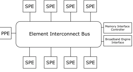
A single Cell chip consists of nine processors - one main processor called the PowerPC Processor Element (PPE) and eight coprocessors called Synergistic Processor Elements (SPEs). They are all connected via the Element Interconnect Bus (EIB), a high-bandwidth memory-coherent bus which is used by the processors to communicate with each other, ex-ternal memory and I/O devices (see Figure1). Compatible devices such as another CBE can also be attached through the CBE interface.
SPE SPE SPE SPE
SPE SPE SPE SPE Element Interconnect Bus PPE
Memory Interface Controller
[image:2.612.312.528.246.363.2]Broadband Engine Interface
Figure 1: Cell processor overview
3.2.1. The PowerPC Processing Element
The PPE is the main processor that controls the CBE. It con-sists of a dual-threaded SIMD 64-bit RISC PowerPC proces-sor (the PowerPC Procesproces-sor Unit or PPU) and a storage sub-system that governs memory requests from the PPE and ex-ternal requests to the PPE from other processors. The PPE is a general-purpose processor optimized for running control-intensive software such as an operating system, coordinating all processes running on Cell.
3.2.2. The Synergistic Processing Elements
The SPEs are where the bulk of Cell’s computation work gets done. Each SPE consists of a specialized 128-bit SIMD RISC processor (the Synergistic Processor Unit or SPU) and a Memory Flow Controller (MFC). The SPUs are op-timized to run compute-intensive code at the expense of branch-prediction and out-of-order-processing hardware, al-lowing more of the chip to be dedicated to computational work and reducing pipeline depth. Instead of dealing directly with main memory, each SPU contains both 256KB of Local Store SRAM and a 128-entry register file. The SPU uses this Local Store to store both data and instructions for the SPU.
allowing the SPU, PPU, or another SPU to request a data transfer to or from main memory. In this way the SPE’s DMA controller can autonomously transfer data to the Lo-cal Store while the SPU is processing other data, thus dou-ble buffering and hiding the memory latency behind compu-tation time. Each DMA transfer can be up to 16,384 bytes in size, and an SPU can have up to 16 outstanding DMA requests queued (or 2,048 if using a special DMA-list con-struct, ideally suited for scatter-gather operations). Theoreti-cal peak bandwidth between the MFC and EIB is 25.6GB/s, with a total EIB peak bandwidth of 204.8GB/s. In prac-tice, approximately 17-20GB/s SPU throughput it typically achievable.
3.3. Programming Cell
IBM released the Cell SDK at the beginning of November 2005. Included in the SDK is a GNU toolchain which in-cludes everything needed to compile and link a native Cell application. Also included is a full system simulator which replicates the entire functionality of Cell and can be used to emulate a PowerPC-based Linux kernel compatible with Cell. Applications written in C/C++ and compiled in this simulator using the provided toolchain can then be run on real Cell hardware without alteration.
PPE
SPE SPE SPE
PPE
PPE
SPE SPE SPE
SPE
SPE
SPE
[image:3.612.73.288.361.467.2]Pipelined Parallel Services
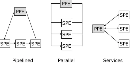
Figure 2: SPE Programming Models
There are three broad programming models for Cell -pipelined, parallel, and service-oriented (see Figure2). The pipelined model has each SPU chained to the next one, us-ing the output of one as the input of another. This allows for high throughput, but is difficult to load-balance. The parallel model runs the same program on each SPU, partitioning and distributing the data to be processed in parallel. The services model is similar to the parallel mode, but each SPU instead processes its data in a different way.
In our case, we are interested in the parallel model. Two program modules are written - one for the PPU and a sepa-rate one for the SPU. All necessary data for the application is loaded and formatted by the PPU, which then distributes the SPU module to each SPU for execution. The SPUs run, retrieving data from main memory as necessary via DMA requests. The PPU then waits for all SPUs to finish their
computation (performing further processing on the results if required) before exiting.
3.4. Applicability to Marching Tetrahedra
Cell is particularly suitable for isosurface extraction by Marching Tetrahedra in two areas; parallelization and data transfer latency/bandwidth.
Parallelization. In MT, the processing of each tetrahedron is independent from the next, requiring no knowledge of its neighbors in order to determine the location of the in-tersecting isosurface (if any). This means that any tetrahe-dron can be distributed to any SPU for independent pro-cessing.
Data transfer bandwidth & latency. Any algorithm deal-ing with volumetric datasets must process large amounts of data, which can quickly become a bottleneck if the sys-tem executing the algorithm is incapable of keeping the processor fed with data. The high bandwidth of the CBE, combined with the SPU’s DMA mechanism for hiding storage latency, eliminates any potential data transfer bot-tlenecks.
4. Implementation
This sections details the adaptation of the Marching Tetra-hedra algorithm for implementation on the Cell processor. Broadly speaking, the process is as follows:
1. The volume is partitioned into slices. 2. The slices are partitioned into chunks. 3. The chunks are assigned to different SPUs.
4. Each SPU iterates over every pair of slices and processes the assigned chunks of those slices.
5. Tetrahedra are constructed by iterating through every 8-cell associated with each voxel in the chunk - four from each adjacent slice.
6. Triangles are produced by evaluating each tetrahedron according to MT.
This involves three steps; volume partitioning, data transfer, and processing.
4.1. Volume partitioning
For each SPU to perform a comparable amount of work, the dataset must be partitioned before it can be distributed. We accomplish this via a two-level partitioning scheme, with the additional aim of minimizing both data replication and trans-fer costs.
contiguous blocks of memory than many small blocks. This format is typically how the data is stored offline on disk.
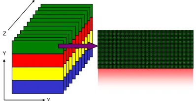
Then every slice is split into n ‘chunks’ for distribution to n available SPUs (see Figure3for an example where n=4). A chunk consists of several rows of data, each chunk over-lapping adjacent chunks by one row. The reason for this is that for each tetrahedron, the Marching Tetrahedra algorithm requires data from 2 adjacent rows in order to build an iso-surface. An SPU works with 2 chunks at a time for the same reason, these chunks coming from two adjacent slices. For each chunk except the last one, the number of rows is cal-culated by the formula round((r+ (s−1))/s), where r is the number of rows not yet assigned to an SPU, and s is the remaining number of SPUs including the current one. The inclusion of(s−1)is to account for the overlapping rows. The final chunk is then assigned all remaining rows.
This method ensures that each SPU receives an approxi-mately equal section of the overall volume. For example if n=8 and y=128, a chunk size of 16 rows will be assigned to the first SPU, with the other seven SPUs being assigned chunks of 17 rows. Thus a total of 135 rows have been as-signed - 128 rows plus the 7 overlapping rows which have been assigned to two SPUs.
X Y
[image:4.612.80.279.347.450.2]Z
Figure 3: Volume slices divided into chunks for distribution to 4 SPUs. Each color represents a separate SPU.
4.2. Data transfer
As described above, the SPU has 256KB of storage imme-diately available to it, which puts a limit on its ability to process locally stored data. Additionally, the only way to transfer data to and from the SPUs local store is via DMA transfers which have a size limit of 16KB. However, the high bandwidth of the EIB and the ability to buffer transfers while still performing computation means that streaming the data becomes an efficient method of processing. Thus the size of the volume being processed is not limited by SPU storage space.
As a result of this, a third level of data partitioning is needed in order to enable the SPU to process chunks of any size. If the size of a chunk is bigger than 16KB, it needs to be broken into sub-chunks of below 16KB for transferring.
The SPU therefore decides how many complete rows can fit into a single DMA transfer, and iterates through the slices processing adjacent sub-chunks to create the isosurface.
This has a direct influence on the amount of data replica-tion necessary. Normally if a chunk fits entirely in one DMA transfer, a volume distributed over n SPUs would need z×
x×(n−1)pieces of replicated data. But for chunks of over 16KB, the amount of replication needed is z×x×(s−1), where s is the number of sub-chunks required.
Whether processing full chunks or sub-chunks, the trans-fer and processing procedure is the same. See Algorithm1
for an overview. Each chunk is used twice by the march-ing tetrahedra algorithm - once as the 8-cell front voxels and once as the 8-cell back voxels. By looping through the slices like this, only one chunk needs to be transferred during any iteration. This keeps data transfer to a minimum, and the buffering can still happen during processing due to the au-tonomous DMA controller. Processing any reasonably-sized chunk takes longer than transferring it, so usually no time is spent waiting for the buffering to complete.
Algorithm 1 Data transfer
1: Transfer chunks from slices 1 and 2 2: for i=1 to numSPU s do
3: if i≤(numSPU s−2)then
4: Start buffering chunk from slice i+2 5: end if
6: Wait for chunks from slices i and i+1 to finish buffer-ing
7: Process chunks (see Algorithm2) 8: end for
4.3. Processing
For every voxel in a chunk, an 8-cell is created consisting of four voxels each from the two adjacent chunks -two voxels from each of -two adjacent rows. Five tetrahe-dra are constructed from this 8-cell as described in Koide et al. [KDK86]. Each tetrahedron is then processed by March-ing Tetrahedra in order to produce zero, one or two triangles.
Algorithm 2 Processing
1: Given two chunks f ront and back 2: for all rows r in chunk f ront do 3: for all voxel v in row r do
4: Create 8-cell from voxels v and v+1 from rows r and r+1 in chunks f ront and back
5: Decompose 8-cell into five tetrahedra 6: Process tetrahedra
7: end for 8: end for
Taking into account the specialized nature of the SPU hardware, certain optimizations can make a difference in execution speed. The lack of branch prediction means that infrequently used branches should be eliminated wherever possible. We build an interpolation table based upon the 16 potential outcomes of tetrahedral evaluation, and per-form vertex interpolation and triangle construction accord-ing to the results of a lookup in this table. This is similar to the methods used by Pascucci et al. [Pas04] and Reck et al. [RDG∗04], where isosurface extraction is performed on graphics hardware that has no branching capabilities.
Similarly, the SIMD capabilities of the SPU must be ex-ploited in order to make full use of the capabilities of Cell. This class of acceleration has been the subject of previous research by Hansen et al. [HH92] as applied to Marching Cubes, and much of this work is still relevant to implement-ing Marchimplement-ing Tetrahedra on Cell.
5. Results
While much of the development of our system was done us-ing the Full System Simulator provided with the Cell SDK, we optimized and tested the performance of our technique on an IBM dual Cell Blade server. This server consists of two 8-SPU Cell processors running at 2.1GHz, with 512MB of XDR DRAM. An equivalent serial algorithm was tested for comparison on a 2.0GHz Pentium 4 system with 1GB of RAM.
Performance tests were carried out on a variety of 8-bit datasets, ranging in size from 323to 5123(see Figures5-9). The amount of free memory on the test machine precluded volumes larger than these - however we did provisionally test a 10243 volume by reusing the 5123 dataset 8 times. This
result (see Figure4) doesn’t take into account the different DMA sizes, cache utilizations and memory access patterns that would occur with a volume that size. Nonetheless, it is included purely as a processing stress test.
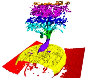
The primary dataset used was a test “Spherical shell” vol-ume (see Figure12) where each scalar value is the Euclidian distance from that point to the center of the volume, mod-ulated by 255 to fit inside a byte. This produces multiple shell isosurfaces for any specified isovalue. Also tested was a 2563 “Bonsai tree” dataset† (see Figure13), and a 5123 “Head aneurysm” dataset‡.
An immediately apparent trend is that as the volumes get smaller, the advantages of adding more SPUs is reduced con-siderably. This continues to the point that adding more SPUs to the 643and 323datasets actually has a detrimental effect on performance. This is because at these sizes, the DMAs
† Courtesy of S. Roettger, VIS, University of Stuttgart ‡ Courtesy of Michael Meißner, Viatronix Inc., USA.
are so small that the cost of setting up and transferring the data is actually higher than the cost of processing it.
We can see that for the spherical shell dataset on one Cell (8 SPUs), we are getting a peak of approximately 47 million tetrahedra per second in both the 5123 and 10243 - a sig-nificant improvement over the CPU’s speed of 5.1 million tetrahedra per second. If we use both Cells we get a peak of over 94 million tetrahedra. This number increases to over 100 million tetrahedra per second for the Bonsai and Head Aneurysm datasets (see Figures10and11). The reason for this is that these volumes are composed of more empty space than the spherical shell - if all 8 voxels of an 8-cell have an isovalue of 0, the whole cell can be skipped safely without being tested.
Furthermore, our results also compare extremely favor-ably to quoted GPU speeds of 9 million tetrahedra per sec-ond [RDG∗04]. However the comparison is only a
superfi-cial one, as current GPU implementations take advantage of spatial acceleration structures which our method currently does not. Additionally, GPU implementations are subject to the condition that the dataset fits entirely into relatively lim-ited video memory. However, GPU speeds also include ren-dering time, whereas our results only measure processing time; an entire processing and rendering pipeline would need to be implemented on both architectures for a fair compari-son to be made.
6. Conclusions and Future Work
In this paper we have introduced the Cell processor and de-scribed the adaptation of Marching Tetrahedra for execution on this new architecture. We have demonstrated peak pro-cessing speeds of over 100 million tetrahedra per second on a dual Cell server, or over 47 million tetrahedra per second on a single Cell. For a single Cell this represents a speed in-crease of over 9 times that of a general purpose CPU, or over 18 times the speed of a CPU in the case of a dual Cell ma-chine. We have shown that these increases have come about through the combination of a streaming and parallelization scheme that takes advantage of Cell’s ability to effectively eliminate memory latency by hiding it behind processing time.
We have also given a general overview of the Cell pro-cessor and described how to leverage its power in the adap-tation of an existing algorithm. This same approach can be used for other compute- and bandwidth-bound algorithms suitable for parallelization, and similar improvements in pro-cessing times can be expected. Moreover, the fact that these improvements can be achieved using a commodity processor means that it is a superior alternative for applications where more processing power is needed, but the cost of expensive dedicated hardware would be prohibitive.
paper concentrates on eliminating memory latency and ef-ficiently transferring data to the SPUs for processing, and does not address the issues of further acceleration by using spatially hierarchical data structures such as octrees [WG92] or interval trees [CMM∗97]. There is little doubt that since
the current limit of our method is the processing time needed by the SPUs, reducing the amount of data to be processed would lead to further increases in speed.
Another issue to be investigated is that of mixing SPU ap-plication models in order to improve overall system perfor-mance. For example, dedicating some SPUs to isosurface ex-traction while the others perform mesh simplification on the polygons already produced. A broad range of load-balancing implications are introduced by the two-tier PPE/SPE split that need to be explored.
Although the streaming methods presented here allow for the processing of very large datasets, the size of system memory still limits the amount of data that can be held at any time. This has implications for very large volume iso-surface extraction, so out of core execution methods such as those proposed by Chiang et al. [CSS98] will also have to be investigated with respect to implementation on Cell.
There is much future work to be done in this area of iso-surface extraction on Cell, and on Cell hardware in general. Because it is a relatively new architecture, its usefulness for compute-, latency- and bandwidth-bound problems is just becoming apparent. A significant change in attitude towards system design is needed in order to use it to its full potential, but as the hardware becomes more widespread and support tools improve, so too will programming paradigms specific to this platform.
7. Acknowledgements
This work is supported by a research grant from Science Foundation Ireland. We would also like to gratefully ac-knowledge Bruce D’Amora at the IBM T.J. Watson Re-search Center for organizing access to Cell hardware there, allowing us to put our ideas into practice.
References
[CFB05] CHOWA. C., FOSSUMG. C., BROKENSHIRE
D. A.: A programming example: Large FFT on the cell broadband engine. IBM White Paper (2005).
[CMM∗97] C
IGNONI P., MARINO P., MONTANI C.,
PUPPO E., SCOPIGNOR.: Speeding up isosurface ex-traction using interval trees. IEEE Transactions on Visu-alization and Computer Graphics 3, 2 (1997), 158–170.
[CSS98] CHIANGY.-J., SILVAC. T., SCHROEDERW. J.: Interactive out-of-core isosurface extraction. In IEEE Vi-sualization ’98 (1998), Ebert D., Hagen H., Rushmeier H., (Eds.), pp. 167–174.
[GH95] GUÉZIEC A., HUMMEL R.: Exploiting trian-gulated surface extraction using tetrahedral decomposi-tion. IEEE Transactions on Visualization and Computer Graphics 1, 4 (1995), 328–342.
[gpg] General-purpose computation using graphics hard-ware. http://www.gpgpu.org.
[GS01] GAOJ., SHENH.-W.: Parallel view-dependent isosurface extraction using multi-pass occlusion culling. Proceedings. IEEE 2001 Symposium on Parallel and Large-Data Visualization and Graphics (2001), 67 – 152.
[HH92] HANSENC. D., HINKERP.: Massively parallel isosurface extraction. In VIS ’92: Proceedings of the 3rd conference on Visualization ’92 (Los Alamitos, CA, USA, 1992), IEEE Computer Society Press, pp. 77–83.
[ibm05] Terrain rendering engine (TRE). IBM White Pa-per (2005).
[KDK86] KOIDEA., DOIA., KAJIOKAK.: Polyhedral approximation approach to molecular orbital graphics. J. Mol. Graph. 4, 3 (1986), 149–155.
[KW05] KIPFERP., WESTERMANNR.: GPU construc-tion and transparent rendering of iso-surfaces. In Pro-ceedings Vision, Modeling and Visualization 2005 (2005), Greiner G., Hornegger J., Niemann H., Stamminger M., (Eds.), IOS Press, infix, pp. 241–248.
[LC87] LORENSEN W. E., CLINE H. E.: Marching cubes: a high resolution 3D surface construction algo-rithm. Computer Graphics (SIGGRAPH ’87 Proceedings) 21, 4 (1987), 163–170.
[Pas04] PASCUCCIV.: Isosurface computation made sim-ple: Hardware acceleration, adaptive refinement and tetra-hedral stripping. Joint Eurographics - IEEE TVCG Sym-posium on Visualization (VisSym) (2004), 293–300.
[RDG∗04] R
ECK F., DACHSBACHER C., GROSSO R.,
GREINER G., STAMMINGER M.: Realtime isosurface
extraction with graphics hardware. Computer Graphics Forum 22, 3 (2004), 595–603.
[SNS∗05] S
AKAMOTOM., NISHIYAMAH., SATOHH.,
SHIMIZUS., SANUKIT., KAMIJOHK., WATANABEA.,
ASAHARAA.: An implementation of the feldkamp
al-gorithm for medical imaging on cell. IBM White Paper (2005).
[WG92] WILHELMSJ., GELDERA. V.: Octrees for faster isosurface generation. ACM Trans. Graph. 11, 3 (1992), 201–227.
[ZBBF01] ZHANGX., BAJAJC., BLANKEW., FUSSELL
Spherical Shell dataset (1024³)
0 10 20 30 40 50 60 70 80 90 100
1 2 4 8 12 16 N u m b e r o f p ro c e s s o rs
Millions of tetrahedra per second
[image:7.612.95.265.74.197.2]CPU SPUs
Figure 4: Test results for the 10243Spherical shell volume
Spherical Shell dataset (512³)
0 10 20 30 40 50 60 70 80 90 100
1 2 4 8 12 16 N u m b e r o f p ro c e s s o rs
Millions of tetrahedra per second
[image:7.612.334.504.75.197.2]CPU SPUs
Figure 5: Test results for the 5123Spherical shell volume
Spherical Shell dataset (256³)
0 10 20 30 40 50 60 70 80 90 100
1 2 4 8 12 16 N u m b e r o f p ro c e s s o rs
Millions of tetrahedra per second
[image:7.612.94.266.227.349.2]CPU SPUs
Figure 6: Test results for the 2563Spherical shell volume
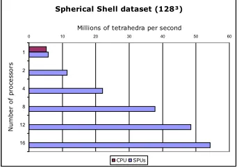
Spherical Shell dataset (128³)
0 10 20 30 40 50 60
1 2 4 8 12 16 N u m b e r o f p ro c e s s o rs
Millions of tetrahedra per second
CPU SPUs
Figure 7: Test results for the 1283Spherical shell volume
Spherical Shell dataset (64³)
0 2 4 6 8 10 12 14 16 18 20
1 2 4 8 12 16 N u m b e r o f p ro c e s s o rs
Millions of tetrahedra per second
[image:7.612.331.506.228.347.2]CPU SPUs
Figure 8: Test results for the 643Spherical shell volume
Spherical Shell dataset (32³)
0 1 2 3 4 5 6
1 2 4 8 12 16 N u m b e r o f p ro c e s s o rs
Millions of tetrahedra per second
[image:7.612.333.505.381.503.2]CPU SPUs
Figure 9: Test results for the 323Spherical shell volume
Bonsai Tree dataset (256³)
0 20 40 60 80 100 120
1 2 4 8 12 16 N u m b e r o f p ro c e s s o rs
Millions of tetrahedra per second
CPU SPUs
Figure 10: Test results for the Bonsai Tree volume
Head Aneurysm dataset (512³)
0 20 40 60 80 100 120
1 2 4 8 12 16 N u m b e r o f p ro c e s s o rs
Millions of tetrahedra per second
CPU SPUs
[image:7.612.96.264.382.503.2] [image:7.612.333.505.535.656.2] [image:7.612.94.266.536.657.2]Figure 12: The 1283spherical shell volume. Each colour represents the isosurface extracted by a different SPU.
[image:8.612.158.437.396.651.2]