Exploring, Reasoning with and Validating Directed Graphs
by Applying Formal Concept Analysis to Conceptual
Graphs
ANDREWS, Simon <http://orcid.org/0000-0003-2094-7456> and POLOVINA,
Simon <http://orcid.org/0000-0003-2961-6207>
Available from Sheffield Hallam University Research Archive (SHURA) at:
http://shura.shu.ac.uk/19112/
This document is the author deposited version. You are advised to consult the
publisher's version if you wish to cite from it.
Published version
ANDREWS, Simon and POLOVINA, Simon (2018). Exploring, Reasoning with and
Validating Directed Graphs by Applying Formal Concept Analysis to Conceptual
Graphs. In: CROITORU, Madalina, MARQUIS, Peter, RUDOLPH, Sebastian and
STAPLETON, Gem, (eds.) Graph Structures for Knowledge Representation and
Reasoning : 5th International Workshop, GKR 2017, Melbourne, VIC, Australia,
August 21, 2017, Revised Selected Papers. Lecture Notes in Artificial Intelligence
(10775). Springer, 3-28.
Copyright and re-use policy
See
http://shura.shu.ac.uk/information.html
Exploring, Reasoning with and Validating
directed graphs by applying Formal Concept
Analysis to Conceptual Graphs
Simon Andrews and Simon Polovina
Conceptual Structures Research Group, Communication and Computing Research Centre| Department of Computing, Sheffield Hallam University, Sheffield, UK
{s.andrews, s.polovina}@shu.ac.uk
Abstract. Although tools exist to aid practitioners in the construction of directed graphs typified by Conceptual Graphs (CGs), it is still quite possible for them to draw the wrong model, mistakenly or otherwise. In larger or more complex CGs it is furthermore often difficult–without close inspection–to see clearly the key features of the model. This paper thereby presents a formal method, based on the exploitation of CGs as directed graphs and the application of Formal Concept Analysis (FCA). FCA elucidates key features of CGs such as pathways and dependencies, inputs and outputs, cycles, and joins. The practitioner is consequently empowered in exploring, reasoning with and validating their real-world models.
1
Introduction
A directed graph–or “digraph”–is a graph whose edges have direction and are called arcs [9,11]. Arrows on the arcs are used to encode the directional informa-tion: an arc from vertex A to vertex B indicates that one may move from A to B but not from B to A. Such graphs for example are used in computer science as a representation of the paths that might be traversed through a program, or in higher-level conceptual models where concepts are related to each other by relations that gain additional semantics (i.e. meaning) by defining the direction between the source and target concepts. A classic illustration is a cat that sits on a mat [18]. In this simple example ‘sits-on’ is the semantic relation where the direction goes from cat to mat and not vice versa.
is correct in terms of its validity. The modeller may have a misconception of the system being modelled or may simply make mistakes in its construction–things that still conform to the syntax and grammar but result in an invalid model.
It can be difficult to explore and validate a large and complex CG by in-spection. It is this problem that this paper addresses by providing an automated method whereby key features of CGs are captured, reported and visualised. The modeller would thus be assisted in exploring and validating their CGs. The method makes use of the inherent direction of Concept-relation-Concept triples in CGs to transform these triples into binary relations and thus expose them to Formal Concept Analysis (FCA) [8]. The process is automated in a tool called
CGFCA and has two stages; firstly parsing a CG file (in the ISO common logic
cgif format [19]) to extract the CG triples and secondly, converting these triples into corresponding binary relations that accentuate the directed pathways in the original CG, as described next in section 2. The triples-to-binaries function is carried out using an implementation of theTriples2Binaries algorithm, specifi-cally described in subsection 2.2.
2
Transforming CG digraphs: triples into binary relations
If triples are extracted from a CG in the form Source Concept → relation →
Target Concept, each such triple can easily be represented as a corresponding binary relation i.e. Source Concept-relation, Target Concept. Where the Tar-get Concept then becomes a Source Concept for a following relation, this can be captured in additional binary relations, where the original Source Concept-relation is paired with subsequent Target Concepts. To illustrate the
source-Fig. 1: Simple CG Fig. 2: FCL for Simple CG
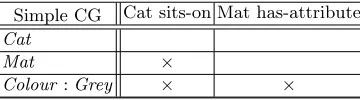
target structure, Figure 1 shows a simple CG with the CG Concepts, [Cat],
[Mat] and [Colour: Grey]. [Cat] and [Mat] are linked by the CG relation
pair [Cat]→(sits-on)and thetarget Concept[Colour:Grey]is dependent on itssource Concept-relation pair [Mat]→(has-attribute)(or alternatively, the
source Concept-relation pair [Cat] → (sits-on)results in thetarget Concept
[Mat]and thesource Concept-relation pair [Mat]→(hasattribute)results in thetarget Concept[Colour: Grey]). The CG triple ([Cat],(sits-on),[Mat]) can be converted into the binary relation ([Cat]-(sits-on), [Mat]). Likewise the CG triple ([Mat],(hasattribute),[Colour: Grey]) can be converted into the binary relation ([Mat](has-attribute), [Colour: Grey]).
There is also a binary relation between[Cat]and[Colour: Grey]indirectly through[Cat]-(sits-on). Hence[Colour: Grey]also depends (indirectly) on
[Cat], which is of course sitting on that mat.
Simple CG Cat sits-on Mat has-attribute
Cat
Mat ×
[image:4.612.217.397.269.319.2]Colour:Grey × ×
Fig. 3: The simple CG as a cross-table
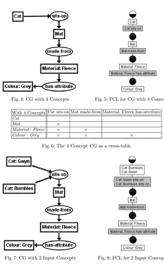
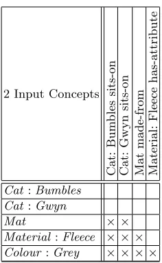
The set of binary relations can be simply represented in a cross-table and Figure 3 shows the corresponding cross-table for this simple example, with rows representing CG Concepts and columns CG Source Concept-relations. The cross-table is known as a Formal Context in FCA, so by converting CGs into these binary relations, FCA can then be applied. Figure 2 displays the resulting Formal Concept Lattice (FCL). This approach was derived after we compared it with Wille’s mapping of CGs to FCA (‘Concept Graphs’) in an earlier study [5, 20]. Figures 4, 5, and 6 show the CG, FCL and cross-table (Formal Context) for a larger CG using the same Cat on Mat example. Figures 7, 8, and 9 show the CG, FCL and cross-table for a further extended version of this example. This time it has two input CG Concepts,[Cat: Gwyn]and[Cat: Bumbles]thus depicting the specific cats Gwyn and Bumbles as the respective CG referent for each CG Concept as shown.
2.1 Obtaining triples from a Conceptual Graph: a parser for cgif
To automate this process, a parser was created that operates on the standard CG file format,cgif. To illustrate the format, below is thecgif for the ‘Cats on the Mat’ CG in Figure 7:
[Material: Fleece] [Cat: Gwyn] [Mat: *x1] [Cat: Bumbles] [Colour: Grey] (sits-on Bumbles Gwyn ?x1)(has-attribute Fleece Grey)(made-from ?x1 Fleece)
The first line in thecgif defines the CG Concepts and the second line defines the CG relations. In line with CGs theory where the referent is unknown, cgif
Fig. 4: CG with 4 Concepts Fig. 5: FCL for CG with 4 Concepts
With 4 Concepts Cat sits-on Mat made-from Material: Fleece has-attribute
Cat
Mat ×
Material:Fleece × ×
[image:5.612.130.467.94.636.2]Colour:Grey × × ×
Fig. 6: The 4 Concept CG as a cross-table
[image:5.612.136.456.110.286.2] [image:5.612.355.453.406.607.2]2 Input Concepts Cat: B u m bles sits-on Cat: Gwyn sits-on Mat made-from Material: Fleece has-attribute
Cat:Bumbles Cat:Gwyn
Mat × ×
[image:6.612.249.367.111.303.2]Material:Fleece × × × Colour:Grey × × × × Fig. 9: The 2 Input CG as a cross-table
comprising one or more source CG Concept referents and a target CG Concept referent. The final referent in the list is always the target referent. Thus, in the relationmade-from,x1is the source andFleeceis the target, and in the relation
sits-on,BumblesandGywn are sources andx1is the target.
The parser first extracts the CG Concepts from thecgif, creating an integer index for each CG Concept and separating the type labels and referents (see Table 1a). The parser then extracts the CG relations from thecgif, creating an integer index for each CG relation and separating the type labels and lists of referents (see Table 1b).
No. Label Referent 1 Material Fleece 2 Cat Gwyn
3 Mat x1
4 Cat Bumbles 5 Colour Grey
(a) CG Concepts
No. Label Referents 1 sits-on Bumbles Gwyn x1 2 has-attribute Fleece Grey 3 made-from x1 Fleece
(b) CG relations
Table 1:
Information extracted by parser from Cats on the Matcgif
parser compares the two Concept labels. If they are different, it concatenates the new label with the existing label in the list, if not the parser simply moves on to the next Concept in thecgif. A similar process is carried when parsing the CG relations in the cgif, but here it is the list of referents associated with the relation that is compared: for two CG relations to be co-referent they must have the same sources and target. For examples of joining co-referents see Section 4.8. Once the CG Concepts and relations have been extracted (and any co-referent joins made), the parser then uses the referents for each relation to create cor-responding triples by looking up the index number of the relation’s source and target CG Concepts corresponding to the relation’s referents. Table 2 contains the triples created from Table 1. The triples thus created are now ready for the process of converting them to corresponding binary relations.
Source relation Target
4 1 3
2 1 3
1 2 5
3 3 1
Table 2: Cats on the Mat triples
2.2 A triples-to-binaries algorithm
Figure 10 is an algorithm,Triples2Binaries, that along with its subroutine Ad-dBinary (Figure 11), converts a set of triples, T, into a corresponding set of binaries, B, exploiting the direction in the triples as explained above. It is a generalised form of theCGtoFCAalgorithm previously presented [5]. Whilst its application to CGs is the focus of this paper, the more general form makes it applicable to directed triples obtained from any source, including UML, RDF, OWL, the Entity-Relation Diagram and linked data. Triples2Binaries also in-cludes some refinements not present inCGtoFCA, namely; the ability to detect ‘direct pathways’ and cycles in a CG. A direct pathway through a CG is a path from an input CG Concept to an output CG Concept, where an input CG Con-cept is one with no edges entering it and an output CG ConCon-cept is one with no edges leaving it. Features such as direct pathways and cycles often have signifi-cant meaning in a CG but are not always easily apparent (particularly in large CGs). The main algorithm,Triples2Binaries, simply iterates through the set of triples,T, sending each triple, (s,r,t) to the subroutineAddBinary. In (s,r,t),
s denotes thesource,r denotes therelation andt denotes thetarget. Each triple enumerated inTriples2Binaries will be the start of a new pathway. A pathway is recorded by AddBinary as a set of (source,relation) pairs inpath.
Line 4 is a test for detecting a direct pathway in the CG: if the current source,
s, is an input CG Concept and the current target,t, is an output CG Concept, then there is a direct pathway froms tot. In which case, the current path along witht is recorded as a direct pathway.
Line 6 is the condition for detecting a cycle in the CG: if the current source,
s, is the same as the current target, t, there is a cycle, recorded in line 7 as the current path along with the current target.
Line 8 defines the terminating condition for recursion (thus preventing infinite loops around cycles): if the current target,t, is already in the current path then
AddBinary terminates. Otherwise, line 9 iterates through the set of triples, T, to test for links (line 10): if the current target, t, also appears as a source,i, in the set of triples, AddBinary is called recursively (line 11), passing the current source,s, the current relation,r, and the new target,k.
Note that the condition for a cycle (line 6) cannot be used as the terminating condition for recursion. This is because the starting point for a cycle can occur at any point in a pathway. A pathway begins with the source,s, and if the starting point of a cycle begins later thans, thenswill never equalt and we would have an infinite loop around that cycle.
begin
1
path← ∅
2
foreach(s,r,t)∈T do
3
AddBinary(s,r,t,path) 4
end
5
Fig. 10:Triples2Binaries(T)
3
The CGFCA Tool
begin
1
path←path∪ {(s,r)}
2
B←B∪ {((s,r),t)}
3
if IsInput(s) andIsOutput(t)then
4
RecordDirectPathway(path,t) 5
if s=t then
6
RecordCycle(path,t) 7
if ¬ ∃(x,y)∈path|t=x then
8
foreach(i,j,k)∈T do
9
if t=i then
10
AddBinary(s,r,k,path) 11
end
12
Fig. 11:AddBinary(s,r,t,path)
((source Concept, relation), target Concept) binaries computed by Triples to Binaries are then passed to a simple Formal Context Creator where the (source Concept, relation) in each binary is treated as a formal attribute and each tar-get Concept is treated as a formal object. The formal context is output in the standard cxt format for FCA.
Fig. 12: CGFCA Architecture
Con-Exp)1 or as a Formal Concept Tree using In-Close [3, 4]. Such visualisations
clearly highlight further CG features such as cycles and co-referent joins.
4
Highlighting key features of a CG using CGFCA
This Section uses simple CG examples to illustrate the use of the CGFCA tool in detecting and highlighting features of CGs and how corresponding FCLs allow a CG to be explored in a formal, hierarchical, visualisation.
4.1 Paths and Dependencies
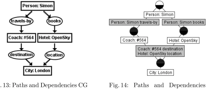
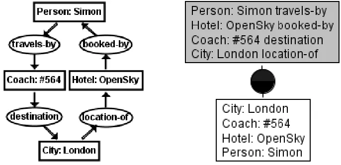
[image:10.612.149.483.396.541.2]Figures 13 and 14 respectively illustrate the CG and FCL for the dependen-cies described earlier in a larger example–as well as two paths–between the source Concept[Person: Simon]and the target Concept[City: London]. As well as the intermediate target Concepts that in turn become source Concepts (i.e.[Coach: #564]and[Hotel: OpenSky]), this example shows CG referents, namely Simon, #564, OpenSky and London. ([Colour: Grey] from Figure 2 was also a CG Concept with a referent.) The referents are instances of their re-spective type label in the CG Concept e.g. London is a referent of the type label City, and #564 the numeric identifier for a Coach that in the context of Figure 13 could be read as the number of the coach that goes to London. In addition
Fig. 13: Paths and Dependencies CG Fig. 14: Paths and Dependencies FCL
to the direct dependencies such as [Hotel: OpenSky]) on [Person: Simon]
-(books)there are indirect dependencies detected in accordance withAddBinary
line 4 described earlier in subsection 2.2. These are: a) [City: London]) on
[Person: Simon]-(books), and b) [Person: Simon]-(travels-to) through the other path that has the intermediate Concept [Coach: #564]. The start-ing (or input) Concepts and endstart-ing (or output) Concepts are usefully reported
1
by the CGFCA software i.e. Inputs: “Person: Simon”. Outputs: “City: London”. The output also states:Direct Pathway: Person: Simon - books - Hotel: OpenSky - location - City: LondonandDirect Pathway: Person: Simon - travels-by - Coach: #564 - destination - City: London.
In simple terms, Simon’s trip to London depends on travelling there by coach and booking into the OpenSky hotel. Of course in this still-simple example this knowledge can be gleaned from the CG alone thereby obviating the need for
CGFCA. However it is more likely that these patterns will appear in larger CGs where it is not so evident, perhaps unknowingly as they are drawn by hand and obfuscated by the size of the larger model. CGFCA and the consequent computer-generated FCL will highlight within such digraphs the ‘diamond’ look-ing patterns that represent multiple pathways thus alertlook-ing their existence–hence validity–to the modeller.
4.2 Cycles
[image:11.612.139.482.351.517.2]It is natural that digraphs may contain one or more cycles. Figures 15 and 16 respectively illustrate an example of a CG and FCL that is a cycle. Note
Fig. 15: CG that is a cycle Fig. 16: FCL of cycle
it does:There are no inputs. There are no outputs. Cycle: City: London - locationof Hotel: OpenSky bookedby Person: Simon travelsby Coach: #564 -destination - City: London. Every Concept is dependent on all the other Concepts with no hierarchy, thus they become grouped together in the FCL.
4.3 Joins
Figure 17 and 18 respectively illustrate the CG and FCL for Concepts that are co-referent. Co-referents occur when Concepts have the same referent, which in this case is Gywn in Pet and Cat. Where a source and target Concept are
Fig. 17: CG with co-referent concept Fig. 18: FCL with co-referent con-cept
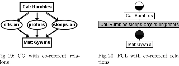
[image:12.612.139.350.263.358.2]directly linked by more than one relation, the associated relations are in effect co-referent. This behaviour is highlighted by Figure 19 and 20.
Fig. 19: CG with co-referent rela-tions
Fig. 20: FCL with co-referent rela-tions
Before theTriples2Binariesalgorithm inCGFCA is called, theCGFCA cgif
[image:12.612.139.478.456.582.2]The outcome is evident in the FCL for Figure 18 (i.e.Pet;Cat) and 20 (i.e.
sleeps-on;sits-on;prefers). This approach is akin to the maximal common subtype in CGs (or intersection); thus Gywn is a) a Pet Cat, and b) sleeps, sits on, and likes the Mat2.
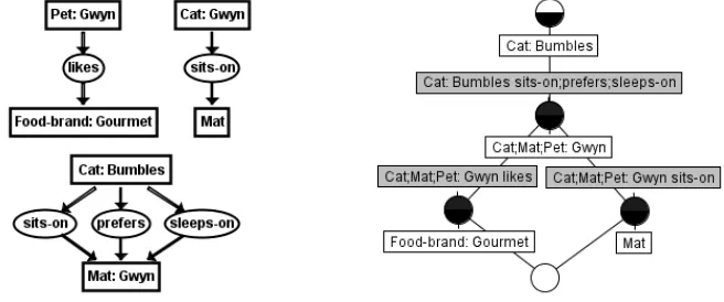
[image:13.612.154.273.268.406.2] [image:13.612.154.482.270.407.2]A common error (particularly in larger or more complex models) is to give different types the same referent by mistake. Take for example the CG Figure 19. In that Figure let’s change[Mat: Gwyn’s]to [Mat: Gwyn], assuming that it was mistyped by the modeller in the first place. As a result,[Mat: Gwyn]will inadvertently join with the[Cat: Gwyn]and[Pet: Gwyn]CGs from Figure 17. Figure 21 shows the CGs for this scenario including the mistake, and Figure 22 demonstrates the result. Now Gwyn is not only a Pet Cat but a Mat too! And
Fig. 21: CG with co-referents Fig. 22: Mistakenly Joined CGs FCL
Bumbles sleeps-on, sits-on and prefers Gwyn as a Mat (rather than Gwyn’s Mat) while Gwyn sits on another Mat, all of which is nonsensical as the FCL reveals. Like the previous pathways and cycles examples, the practitioner is immediately presented with a need to reason with and validate their models.
4.4 n-adic
Apart from Figure 7 earlier, the CG relations so far have been2-adic i.e. only one source CG Concept pointing to the relation. 2-adic CG relations are also known asdyadicCG relations. A CG relation may however have more than one source CG Concept; hence an n-adic CG relation has n source CG Concepts. The CG relationsits-onin Figure 7 is3-adic, ortriadic.
Figure 23 and Figure 25 highlights the relation sits-on being stated as being dyadic or triadic respectively. CG relations may any number of source CG Concepts pointing to them3. Figure 24 and Figure 26 reveal that the FCL
2 NoteMathere has a latent referent, in accordance with CGs theory; hence we can
simply refer to it through the definite article ‘the’.
3
[image:13.612.325.480.273.405.2]Fig. 23: CG with 2-adic relation Fig. 24: FCL with 2-adic relation
Fig. 25: CG with 3-adic relation Fig. 26: FCL with 3-adic relation
for Figure 23 and Figure 25 turn out to be identical, thus two representations of the same meaning. Unsurprisingly, the CGFCA output is identical for both the 2-adic and the 3-adic: Inputs: ”Cat: Gwyn” ”Cat: Bumbles” Outputs: ”Mat: Gwyn’s” Direct Pathway: Cat: Gwyn - sits-on - Mat: Gwyn’s Direct Pathway: Cat: Bumbles - sits-on - Mat: Gwyn’s.
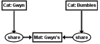
Fig. 27: CG, ‘wrong’ 2-adic share Fig. 28: FCL, ‘corrected’ share
[image:14.612.133.294.428.500.2]Certain CG relations such as ‘(share)’ inherently can only have certain n-adic values. For the share case, there need to be two or more things to have something shared between them, hencesharehas to be at least triadic i.e.≥ 3-adic. AsCGFCAwould provide the same outcome even if theshareCG relation was modelled as dyadic accidentally by the modeller, it would still be correctly depicted in the FCL. For completeness, Figures 27, 28, 29 and 30 respectively demonstrate this outcome.
4.5 Formal Concepts without their own Attributes or Objects
[image:15.612.133.293.333.450.2]Unlike the examples shown thus far where it has only occurred at the bottommost (or infimum) Formal Concept in an FCL, CGs may generate an FCL that has Formal Concepts without their own attributes (i.e.Source Concept-relation) or objects (i.e.Target Concept) in the middle of the FCL. Figure 31 has generated such a formal concept as evident in Figure 32.
Fig. 31: CG leading to unlabelled FC Fig. 32: FCL with unlabelled FC
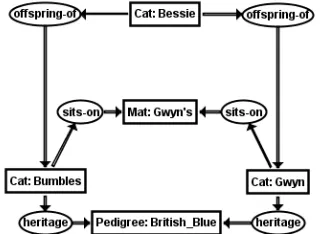
[image:15.612.333.471.333.452.2] [image:15.612.136.289.520.644.2]Essentially this is because [Cat: Bumbles]and [Cat: Gywn] both sit-on
the [Mat: Gwyn’s] and have the heritage of [Pedigree: British Blue]. This pattern can be gleaned from the correspondingCGFCAoutput for Figures 31 and 32:
Inputs: ”Cat: Bessie” Outputs: ”Mat” ”Pedigree: British Blue”
Direct Pathway: Cat: Bessie - offspring-of - Cat: Bumbles - heritage - Pedigree: British Blue
Direct Pathway: Cat: Bessie - offspring-of - Cat: Bumbles - sits-on - Mat Direct Pathway: Cat: Bessie - offspring-of - Cat: Gwyn - sits-on - Mat
Direct Pathway: Cat: Bessie - offspring-of - Cat: Gwyn - heritage - Pedigree: British Blue
The only way to traverse the FCL to capture these relations is through the unlabelled Formal Concept in between.
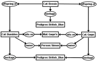
Figure 33 and Figure 34 evidence the pattern in a larger example where, essentially,[Cat: Bumbles]and[Cat: Gywn]both sit-onthe[Mat: Gwyn’s]
andhave theheritageof[Pedigree: British Blue],andhave as theirowner
the[Person: Simon]. TheCGFCA output underpins the pattern:
Inputs: ”Cat: Bessie” Outputs: ”Person: Simon” ”Mat: Gwyn’s” ”Pedigree: British Blue” Direct Pathway: Cat: Bessie - offspring-of - Cat: Bumbles - owner - Person: Simon Direct Pathway: Cat: Bessie - offspring-of - Cat: Bumbles - heritage - Pedigree: British Blue
Direct Pathway: Cat: Bessie - offspring-of - Cat: Bumbles - sits-on - Mat: Gwyn’s Direct Pathway: Cat: Bessie - offspring-of - Cat: Gwyn - heritage - Pedigree: British Blue Direct Pathway: Cat: Bessie - offspring-of - Cat: Gwyn - owner - Person: Simon Direct Pathway: Cat: Bessie - offspring-of - Cat: Gwyn - sits-on - Mat: Gwyn’s.
4.6 Further Exploring n-adity
For Figure 33 we can also identify the presence of 3-adic (triadic) relations, as CG Figure 35 reveals. Note once more that the FCL Figure 36 is identical to Figure 34.
Figure 37 has a CG withheritageas a 4-adic relation, essentially adding that [Cat: Bessie] has the heritage of [Pedigree: British Blue] too, along with[Cat: Bumbles]and[Cat: Gywn]. Through the unlabelled Formal Concept the 4th adic is highlighted by Figure 38.
4.7 Further Exploring co-referent links
Fig. 35: Same CG, 3-adic Fig. 36: Resulting same FCL
[image:17.612.134.291.513.614.2] [image:17.612.341.464.513.610.2]Fig. 37: CG, with 4-adic Fig. 38: FCL, with 4-adic
[14, 17, 19]. The significance of this example is that it reminds us that CGs may be hand-drawn in different ways (e.g. different adity, or using co-referents advertently–or inadvertently as we saw with[Mat: Gwyn]in CG Figure 21 and the corresponding FCL Figure 22). However the FCL will represent them in
one way, thus potentially removing multiple, and potentially confusing ways of stating the same thing differently.
4.8 Larger Joins
Lastly to illustrate the wider behaviour of digraphs through CGs the above-discussed examples are essentially joined into one CG. Figure 41 shows the re-sult of joining the other CGs (except Figure 15) with Figure 13, which showed the dependency from[Person: Simon] to[City: London] without the cycle, whereas Figure 42 shows the result of joining the other CGs (except Figure 13) to Figure 15, which showed [Person: Simon] to (and from) [City: London]
[image:18.612.322.480.246.361.2]with the cycle.
Fig. 41: Joined FCL no cycle Fig. 42: Joined FCL with cycle
5
A Realistic Example
The simple but expressive examples presented thus far demonstrate how di-graphs can be explored and validated through Triples2Binaries as exemplified byCGFCA. Previous work has indicatedCGFCA’s value in the business infor-mation systems modelling domain [15]. Based on an example from that work, a more comprehensive example is now presented from that real-world domain. Whilst the example uses the terminology of that domain, this example will be explained such that it can be more widely understood.
5.1 The Current Situation
Fig. 43: Application Module CG
demonstrate digraphs’ applicability in higher-level conceptual models where con-cepts are related to each other by relations that gain additional semantics (i.e. meaning) by defining the direction between the source and target concepts.
CGs (Conceptual Graphs) are an expressive form of digraphs that enable modellers to express meaning in a form that is logically precise whilst being humanly readable. As such, they provide a conceptual structure that can for-mally describe the given problem being modelled. CGs, in common with many other forms of diagraphs are however drawn by hand, even with the assistance of software tools such as CoGui suggested earlier [2]. Currently, the modeller enters the digraphs–in this case CGs–into the tool manually and relies on the tool to work with the potentially erroneous CGs entered into it. In effect the tool is as only as good as the fool that uses it, so “a fool with a tool is still a fool”–a common criticism from industry [12]. While a business (or other) mod-eller may be no fool, there is no guarantee that a model created using CGs is correct in terms of its validity. In their exploration of the given problem using CGs, the modeller may have a misconception of the system being modelled or may simply make mistakes in its construction–things that still conform to the syntax and grammar but result in an invalid model. The current situation is too complicated, and presents an unwarranted burden on the modeller.
complications as described above. We now further test this effectiveness using business modelling as the more comprehensive illustration.
5.2 Understanding the Complications
The CG Figure 43 describes the components of a software application module that is part of an information system in an organisation. Applying CGFCA as above, Figure 44 is the corresponding FCL for this CG Figure. The human busi-ness modeller draws this CG to capture the entities as CG Concepts and the CG relations between them. The detailed meaning of each entity and relation is discussed elsewhere [15], but for the purposes of our understanding the appli-cation module is denoted by the CG Concept: [Application Module: am1A]. The referent ‘am1A’ uniquely identifies the application module. The remaining CG Concepts and relations flow down from[Application Module: am1A]. This is validated by Application Module: am1Abeing at the supremum (topmost) Formal Concept of the lattice, Figure 44. The modeller requires each referent throughout this CG to be unique and have no cycles in it. Figure 44 evidences that the Application Module as a CG is accurately captured. In practice this is unlikely to be the case. What are the complications in drawing the model that can undermine its validity, and how are these complications revealed byCGFCA
and the lattice?
Arrow Direction. A common mistake or misconception that a modeller can make is to draw the arrows the wrong way round. This is a complication that may seem obvious on close inspection of the CG but nonetheless easily occurs even in introductory CGs despite proof-checking [14]. The syntax of the CG is correct–i.e. it is still a digraph (directed graph)–but this act results a semantic error. Figure 46, which is an extract of the lattice for the CG Figure 45 shows that Application Module: am1A is not at the supremum; its place is taken by Organizational Unit: ou1A. This change of input is also shown by the CGFCA report:Inputs: ”Organizational Unit: ou1A”. The modeller is alerted to this deficiency because the arrows between [Application Module: am1A]and
[Organizational Unit: ou1A] in CG Figure 45 were accidentally drawn the other way, unlike in the correctly-drawn previous CG Figure 43. The modeller can then correct the model. The modeller may want to manually record the mis-take for future reference, by shading the ’offending’(assigned to)CG relation as shown in Figure 45.
Mispointed Arrows. The CG Figure 47 highlights another common mistake (or misconception) where a CG relation is pointed to the wrong CG Con-cept. In this case it’s [Transaction Code: tc3A] → (assigned to) → [IT Governance: itg4A]. It should be[Transaction Code: tc3A]→(assigned to)
Fig. 45: Application Module CG, wrong arrow direction
[image:22.612.249.369.505.590.2]FCL Figure 47 the modeller notices that assigned to;measured by is incor-rectly concatenated in Transaction Code: tc3A assigned to;measured by. Such concatenations were demonstrated earlier by the FCL Figure 20 (i.e.Cat: Bumbles sleeps-on;sits-on;prefers), which was correct in CG Figure 19 but incorrect in CG Figure 47. Again a close inspection of CG Figure 47 would reveal this complication, but it can easily happen in practice.
Fig. 47: Application Module CG extract, assigned to mispointed
Unwanted Cycles. While cycles may be deliberate, in many cases including this business modelling scenario they point to a mistake or misconception. That is the case of the CG Figure 49 that emerges in the FCL of which Figure 50 is an extract. The cycle is still rather subtle however as the FCA attributesBusiness Object: bo3A assigned to,Event: e3A assigned toandApplication Task: at3A assigned to are spread across two Formal Concepts before the FCA objectsBusiness Object: bo3A,Event: e3A assigned toandApplication Task: at3Aare reached showing that the CG Concepts in the attributes (even-tually) point to themselves as the CG Concept denoted by the FCA object. The
CGFCA report brings it most easily to light:
Fig. 48: Application Module FCL extract, assigned to mispointed
[image:24.612.134.480.382.598.2]Fig. 50: Application Module FCL extract, cycle
The FCL is nonetheless of value as the Formal Concept that has the three at-tributes listed above (i.e. Business Object: bo3A assigned to,Event: e3A assigned toandApplication Task: at3A assigned to) doesn’t have its own object (i.e. target CG Concept). This is highlighted by the bottom half of this Formal Concept’s circle being transparent due to the other dependencies in the FCL. The modeller sets those other dependencies aside, as (s)he has identified that the unwanted cycle is the issue and its correction may also resolve any other suspect dependencies (which it does). The cause? That common error of a relation with the arrows pointing the wrong way i.e. the(assigned to)CG relation that points to [Application Task: at3A] from [Business Object: bo3A]when the CG relation should be the other way round. This time it causes a cycle as a revisit to the CG Figure 49 and following this CG relation–using the CGFCA report as our guide–brings the cycle to light. For the record, the offending (assigned to)is shaded in the CG Figure 49. The cycle in the FCL Figure 50 is also highlighted by the rectangles with thick black borders.
high-Fig. 51: Application Module CG, ar3A referent
lighted in thick black border rectangles. Likewise, and as before, the modeller in CG Figure 51 shades these offending CG Concepts.
5.3 Resolving the Complications
While the above complications are not exhaustive, and not accounting for com-binations of complications that could be further highlighted by the approach de-scribed, we have evidenced through the real-world scenario of business modelling how the human modeller as a practitioner (business or otherwise) is empowered byCGFCA and the FCL. In the course of this approach the modeller was able to explore the CG models, apply his/her reasoning from identifying issues in the models, thus leading to their correction. Through resolving the complications, the modeller acts as a human co-creator with the computer-generatedCGFCA
reports and FCLs (Formal Concept Lattices) thereby being empowered to pro-duce useful, validated models.
6
Related Work
[image:26.612.134.481.113.329.2]and Graph-FCA [6, 7, 16]. Extensive comparative studies in this arena already exist, pre-CGFCA [13]. While CGFCA fulfills the scope of our study, there is value in a up-to-date comparative study that includesCGFCA. Such work may help to identify how all the approaches may best work together for directed graphs and FCA.
7
Concluding Remarks and Further Work
As well as providing the capability to explore, reason with and validate directed graphs (digraphs), the FCL representation of CGs are arguably more readable. As we have seen, the arcs (the arrows) in a CG can lead in any direction. In a large, complex CG it can be difficult to trace and compare pathways through it, even more so where there are co-referent links. All FCL pathways are aligned in a top-to-bottom (inputs to outputs), hierarchical manner and co-referents can be automatically joined to make more apparent their connections and place in the graph.
Future work will continue to develop representative exemplars; a worthwhile endeavour given the value demonstrated by this paper. Furthermore since we have set the context as exploring and validating digraphs through triples to binaries rather than just CGs, the further work intends to include directed triples modelled by practitioners in UML, RDF, OWL, the Entity-Relation Diagram and linked data as alluded to earlier.
Meanwhile we have demonstrated thatCGFCA–henceTriples2Binaries–presents a formal method that exploits CGs as digraphs through the application of Formal Concept Analysis (FCA). FCA elucidates key features of CGs such as pathways and dependencies, inputs and outputs, cycles, and joins. Given the prevalence of digraphs, the practitioner is consequently empowered in exploring, reasoning with and validating their models in understanding real-world phenomena.
References
1. Charger - a conceptual graph editor. http://charger.sourceforge.net/. (Accessed on 02/01/2018).
2. Cogui. http://www.lirmm.fr/cogui/. (Accessed on 02/01/2018).
3. Simon Andrews.In-close2, a high performance formal concept miner, pages 50–62. Conceptual Structures for Discovering Knowledge. Springer, 2011.
4. Simon Andrews and Laurence Hirsch. A tool for creating and visualising formal concept trees, volume 1637 ofCEUR Workshop Proceedings, pages 1–9. 2016. 5. Simon Andrews and Simon Polovina.A Mapping from Conceptual Graphs to
For-mal Concept Analysis, pages 63–76. Conceptual Structures for Discovering Knowl-edge. Springer, 2011.
6. Franz Baader and Felix Distel. A Finite Basis for the Set of EL-Implications Holding in a Finite Model, volume 4933 ofLecture Notes in Artificial Intelligence, pages 46–61. Springer, 2008.
8. Bernhard Ganter and Rudolf Wille. Formal concept analysis: mathematical foun-dations. Springer Science & Business Media, 2012.
9. Frank Harary. Structural models: An introduction to the theory of directed graphs.
{John Wiley & Sons Inc}, 1965.
10. Pascal Hitzler and Henrik Scharfe. Conceptual Structures in Practice. CRC Press, 2009.
11. Kenneth R. Koehler. Directed graphs. http://kias.dyndns.org/comath/33.html, 2012.
12. Lindsay Parker and HP OpenView Business Unit. A fool with a tool is still a fool!
HP Open View, 2001.
13. Jonas Poelmans, Dmitry I. Ignatov, Sergei O. Kuznetsov, and Guido Dedene. Re-view: Formal concept analysis in knowledge processing: A survey on applications.
Expert Syst. Appl., 40(16):6538–6560, November 2013.
14. Simon Polovina. An Introduction to Conceptual Graphs, pages 1–15. Conceptual Structures: Knowledge Architectures for Smart Applications, July 2007, Sheffield, UK. Springer, 2007.
15. Simon Polovina, Hans-J¨urgen Scheruhn, and Mark von Rosing. Modularising the Complex Meta-Models in Enterprise Systems Using Conceptual Structures, pages 261–283. Developments and Trends in Intelligent Technologies and Smart Systems. IGI Global, Hershey, PA, USA, 2018. ID: 189437.
16. Mohamed Rouane-Hacene, Marianne Huchard, Amedeo Napoli, and Petko Valtchev. Relational concept analysis: mining concept lattices from multi-relational data. Annals of Mathematics and Artificial Intelligence, 67(1):81–108, 2013. 17. J.F. Sowa. Conceptual structures: Information processing in mind and machine.
Addison-Wesley Pub.,Reading, MA, Jan 1983.
18. John F. Sowa. Conceptual graph examples. http://www.jfsowa.com/cg/cgexampw.htm.
19. John F. Sowa. Conceptual Graphs, pages 213–237. Handbook of Knowledge Rep-resentation, Foundations of Artificial Intelligence. Elsevier, Amsterdam, volume 3 edition, 2008.