©IJRASET: All Rights are Reserved
196
50x50 Elements Phased Array Antenna using
MATLAB and CST
Hazim A. Abdulsada1, Huma Razzaq2
1, 2
Advance communication Engineering, Kent University, Advance communication Engineering, Canterbury, Kent, UK
Abstract: Radiation element of single element is wide and provide low gain and directivity. The formation pattern of multi-element antenna is called Phase Array Antenna. Phase Array Antenna can be achieved by rearranging array multi-elements of antenna in the way that the total fields of element are added in the same direction and cancel each other in the opposite direction. All elements are fed with same phase. A dipole antenna is used for design the phase array with 2.4 GHz. A CST microwave programme is used to verify dipole work on 2.4 GHz. Mainly this project deals with 50X50 phased array using Matlab.
Keywords: Phased array, Dipole, Matlab, Radiation pattern
I. INTRODUCTION
Radiation element of single element of one dipole is wide or omnidirectional and provide low gain and directivity. Omnidirectional radiation suffers from power loss since some power goes far from the area of interest. In many applications, it is necessarily to design an antenna with high gain or directivity, this will also offer transmission for long distances. The formation pattern of multielement antenna based on one or two dimension, when pattern can accumulate in phase in one direction and out phase in the opposite direction is called Phase Array Antennas (PAAs), [1]. There are some measurements that are used in antenna arrays, one of them is Total field of Array. Total field Array is calculated by vector addition of single element in the array which is normally having same current in each element, [1]. A mutual coupling is also one measurement which can be avoided by control the separation between antenna, [1]. The idea behind using array of antenna is to provide very directive antenna which can be achieved by arranging the array of antenna in the way that is total fields of element are added in the same direction and cancel each other at opposite direction, [1]. Several types of array are existed, some of them are used for civil purposes, other for commercial and military purposes. The simplest one and most practical array is line array which is basically arrange the element across line.
There are several ways to control the directivity of antenna but the most important, [1] as follows:
A. One way is used to control geometric configuration such as (linear, circular, rectangular, spherical, ...).
B. Or by make an adjustment of placement of array elements by control the distance between array elements.
C. Amplitude of individual could also be used to control the directive gain by changing the values of each element.
D. Directive gain could also be achieved by control the phase of individual element.
E. Finally, Directive gain can be controlled by pattern of the individual element.
Different types of phased arrays, some off them is uniform array which is using same amplitude and phase or non-uniform which is using different amplitude or phase which is fed to each element. The most popular one is
1) Linear array 2) Planar array 3) Binomial array
II. FEEDING TECHNIQUES
©IJRASET: All Rights are Reserved
197
III. DESIGN TECHNIQUES
A. Dipole Antenna
The design is made to resonate at 2.4GHz. According to the operating frequency, the length, L of half wave dipole can be calculated based on this equation, [2]
The actual length of the patch (L),
L =
( ) (1) The wavelength,
λ = (2)
The feeding gap (g),
g = (3)
Final calculation is the radius also known as thickness of dipole R,
R = (4)
The equations (1-4) show the design of physical dipole antenna for one element, a phase array as explained consists of many dipoles’ antenna, hence an array factor, total fields of array should be calculated.
If we suppose that we are using 2 dipoles array, then total fields radiated by 2 elements is sum of electric fields of two element in Y, Z domain, by assuming no mutual coupling between elements, [1] .
ET= aˆ θ j η
{ e−j[kr1−(β/2)] / r1 .* c o s θ 1 + e−j[kr2+(β/2)] /r2 . * c o s θ 2}
(5) Hence the array total fields can reduce to
ET= aˆ θ j η
e−jkr. cos θ{2 c o s {1/2(kd cos θ + β)}} (6)
From this equation, the total fields of array appear to be the product of total fields of single element with a factor which is most commonly known as array factor,
Therefore, the Array Factor (AF) of 2 elements of constant amplitude is, [1] .
AF= 2 cos [ ½ (kd cos θ + β)] (7)
The characteristic of AF can be changed by varying the separation between element and phase as well, thus total fields can be changed.
E(total) = [E(single element at reference point)] × [array factor].
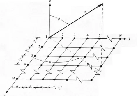
IV. PLANARARRAY
[image:2.612.190.427.547.712.2]Planar arrays are more versatile, they provide interesting symmetrical patterns with lower side lobes, with higher directivity mainly with narrow main beam planar arrays can be deployed to scan the main beam toward any point in space, [1] .
©IJRASET: All Rights are Reserved
198
Since the amplitude excitation coefficients of the elements of the array in the y-direction are proportional to those along the x, theamplitude of the (m, n) the element can be written as Imn = Im1I1n
If in addition the amplitude excitation of the entire array is uniform (Imn = I0) The array factor of a rectangular planar array, [1] .
AFn(θ,Ø)=1/M 1/N (8)
Where ψx = kdx sin θ cosØ+βx and ψy = kdy sin θ cos θ +βy
V. PROPOSED PHASED ARRAY ANTENNA Dipole DESIGN USING CST
[image:3.612.41.549.247.382.2]According to equation (1-6), a design is created by CST to make sure the dipole resonant at correct frequency 2.4GHz, the final result of Dipole can be seen at figure 2.
Figure 2. Design resonant Dipole by CST at 2.4GHz
VI. MATLAB SIMULATION RESULTS
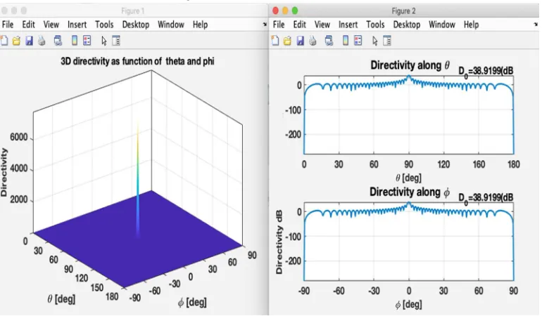
In figure 3, the radiation pattern of normalized plot and 3D plot have shown when the distance between the elements is λ/2. The number of elements is 2500.The obtained Directivity is 38.9 dB with minimum side lobes.
Fig. 3: Radiation pattern when distance between elements is half lambda or λ/2.
In figure 4, the radiation pattern of normalized plot and 3D plot have shown when the distance between the elements is λ/4 or 0. 031m.The number of elements is 2500. The obtained Directivity is 32.8 dB with minimum side lobes.
sin /2ψx
sin 1/2ψx sin /2ψy
[image:3.612.115.505.453.678.2]©IJRASET: All Rights are Reserved
199
Figure. 4. Radiation pattern when distance between elements is λ/4.It is clearly seen that the directivity is decreased by almost 6.1 dB when the separation between elements is quarter lambda so separation as half lambda is better.
[image:4.612.115.500.310.464.2]In figure 5, the radiation pattern of normalized plot and 3D plot have shown when the distance between the elements is λ or 0.125m. The number of elements is 2500.The obtained Directivity is 30.6 dB with minimum side lobes.
Figure. 5. Radiation pattern when distance between elements is λ.
We conclude that separation between elements as Lambda is even worse than quarter lambda, the result not only shows the decrease in directivity of λ/4 by 2.2 dB and 8.3 dB from separation as λ/2, but also, we have side lobes on both sides of main lobes.
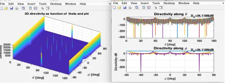
In figure 6, the radiation pattern of normalized plot and 3D plot have shown when the distance between the elements is λ or 0. 125m.The number of elements is 2500.The obtained Directivity is 34.11 dB with minimum side lobes.
Figure 6. Radiation pattern when distance between elements is 2* λ or 0.25m.
[image:4.612.123.498.547.685.2]©IJRASET: All Rights are Reserved
200
VII. CONCLUSION
A phase array antenna has already been used for military applications in the past several decades such as radar. There is a recent trend towards using PAs in civilian application and advanced communication systems. PAs been able to produce a directional beam which can be electronically steered, therefore a significant performance can be achieved in several wireless communications systems. A dipole present simplicity design, high directivity, cheap component, easy to fabricate over other types of array. A separation as lambda/2 show the perfect space between each element of 2 dimension of planar array while increasing spacing as more lambda, many side lobes appear next to main lobes which is in most case not preferable in PAAs. More directivity can be achieved when number of elements is increasing with PAAs.
VIII. ACKNOWLEDGEMENT
The Authors were supported by University of Kent- Advance Communication Engineering Department. We thank our Lecturers (Dr. C Wang and Prof S Gao) from University of Kent who provided insight and expertise that greatly assisted us in the research.
REFERENCES
[1] C. A. Balanis, Antenna Theory, vol. 3rd. New Jersey: Willey, 2005.
[2] J. D. K. and R. J. Marhefka, “White Paper on Antenna Patterns and Their Meaning,” Cisco Aironet Antennas and Accessories, pp. 1–17, 2007. [3] K. R. John.D, “Antennas for All Application.” McGRAW.Hill, New York, 1998.