425
©IJRASET: All Rights are Reserved
Simulation Model of LPG Recovery Plant to
Optimize the Process Parameters
Naeem Akbar1, Muddassar Habib2
1, 2
Chemical Engineering Department, University of Engineering and Technology, Peshawar, Pakistan
Abstract: Controlling the hydrocarbon dew point by extracting NGLs from wet gas is an important step that prevents condensation of hydrocarbon in pipeline for transporting natural gas. Recovering LPG using Turbo Expander is a process where internal energy of system is incorporated. Parameters like flow, temperature and pressure play vital role in determining the extant of LPG recovery from wet gas. In this study, LPG Recovery plant in Pakistan is simulated on AspenTech® HYSYS 10 at steady state mode and the process parameters were optimized. The simulated parameters (Pressure, Temperature, Flow rate) are validated with actual running parameters of plant. Also this simulation study ran case studies for determining the most optimum flow rate of 25.09 bpd of NGL stream which is recycled back to Deethanizer. This recycle stream has increased the LPG production by 2.88 Mton per annum. With improving the production of LPG, NGL condensation in Residual gas is minimized (HCDP dropped from 81.0 to 81.1 °F) which is going into customer pipeline network (M/s SNGPL) who is further distributing this gas at domestic level.
Keywords: LPG Plant, Turbo Expander, Simulation, HYSYS, HCDP
I. INTRODUCTION
Natural gas exist naturally and produced when deposits of decomposing animal and plant remains are pressed with high pressure along with temperature under the deep Earth over millions of years. It is Methane rich Hydrocarbon mixture including different amount of other alkanes, alkenes, alkynes and mostly traces of carbon monoxide, carbon dioxide, hydrogen-sulfide, nitrogen or helium) [1]. Source of Internal energy of these plants originally obtained from sun is preserved in the shape of chemical-bonding in the gas [2]. Other sources of Natural gas are underground formation of rocks, as associated gas with other crude oil reserves, in coal beds and as methane lattice. Over the time, mostly natural gas was created by two methods: thermo-genic and bio-genic. Bio-genic gas formed by methano-genic organisms found in swamps and deep sediments [3] [4] where as thermo-genic gas is formed by buried organic compounds at high temperature and pressure underground. Unfortunately for a long time period, this precious energy source along with other crude oil products was wasted as flaring (approximately over 150 cubic kilometers of natural gas is still flared or cold vented annually in current modern age with developed technologies, according to World Bank sources [5] [6]) Natural gas is mostly not usable at well head [7]. In order to make it marketable as fuel, it must be processed to remove by-products, impure state and impurities like moisture, free water and acid gases (CO2, CO, NOx, SOx) to meet the
specifications of marketable natural gas. Typically, the side-products of treating natural gas are heavier like C2 (ethane), C3
(propane), C4 (butanes), C5 (pentanes) and similarly higher chain hydrocarbons with more atomic weights, H2S (hydrogen sulfide)
which is usually converted in elemental sulphur, CO2 (carbon-di-oxide), free water, sometimes He (helium) and N2.
A. Hydrocarbon Dew Point
The Hydrocarbon dew point (HCDP) has many definitions as it is strongly depending on complex nature of Hydrocarbon. The temperature at which first condensation (formation of condensate) occurs in the gas for a given pressure is known as Hydrocarbon Dew Point. Due to nature of natural gas itself, this connection is complex since it is not expressed by single chemical formula, variety of blends are possible and has many fractions. Due to this, HCDP vary extensively at the given pressure and temperature. One thing is constant; first the heavier components will condense out. Hefty measurement errors will emerge if the amount of these heavier components is not accurately considered. Gas composition, temperature and pressure of the gas are prime factors in deciding HCDP [8].
B. Reasons to Control HCDP
426
©IJRASET: All Rights are Reserved
and overpowering liquid handling arrangements, flowing into compressors resulting in damaging the machines and end user custody transfer points resulting in domestic hazard. Most prominently, liquids in household stoves, flare-pilots at site and at end user locations can cause accidents involving explosion or fire. Also, removing pipeline liquids assist to avoid pipeline corrosion in the low portions where water is trapped under the condensed HC (Hydrocarbon) liquids’ layer and slowly, destroys the pipe integrity. Appropriate managing of HCDP can also avoid liquid forming as the gas cools while flowing through pressure reduction stations (e.g. city gates) that feed domestic supply systems. Controlling HCDP is important to qualify sale gas for the pipeline to market gas, involving feed for high efficiency gas turbine to reach end users that always require a consistent quality and bone dry fuel.
II. PROCESSDESCRIPTION
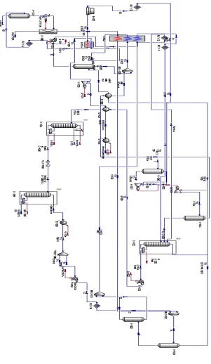
The Simulation is performed as described in figure (Figure 1), for LPG Recovery plant located at Attock, Pakistan which use Turbo Expander technology to recovery Natural gas liquids (NGL) namely Liquefied Petroleum Gas (LPG) consisting mainly of Propane and Butane, Gasoline consisting mainly of Pentane, Solvent Oil consisting mainly of Hexane and heavier hydrocarbon.
13 MMSCFD Sweet gas with composition mentioned in Table 1 is fed to LPG plant [10]. Also a PFD is shown in figure (Figure 2). Plant design is 75 MMSCFD and hence a certain stream is recycled. To avoid free water or hydrocarbons condensed to reach compressor driven expander, whose performance would be severely impaired by such slugs, a Knock Out drum (V106) is installed at the inlet. In order to remove moisture (Dehydrate) up to 0.5 ppm or even less, three molecular sieve dehydrators are utilized, operating on a conventional 12 hours cycle and regenerated at 600 F maximum. To minimize regeneration heat the water content of the inlet gas has been reduced cooling the gas at 80 F and discharging the condensed water from separator (V101) at upstream of the dehydrator.
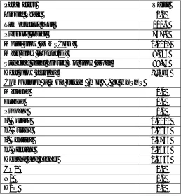
TABLE I Composition of Feed Gas to LPG recovery plant
S# Components Mole Fraction
1 Methane (C1) 0.858
2 Ethane (C2) 0.077
3 Propane (C3) 0.031
4 iso-Butane (i-C4) 0.0068
5 n-Butane (N-C4) 0.0086
6 iso- Pentane (i-C5) 0.0028
7 n-Pentane (N-C5) 0.0022
8 Hexanes plus (C6+) 0.0042
9 Carbondioxide (CO2) 0.0049
10 Nitorgen (N2) 0.0033
11 Hydrogen Sulfide (H2S) 0.0000
427
©IJRASET: All Rights are Reserved
[image:3.612.180.435.145.217.2]Process Conditions Aspen Tech product called as HYSYS Version 10 is used in this study for simulation of the LPG Recovery plant. Basis of simulation of inlet gas with process parameters are given in TABLE II while the Gas composition of the inlet stream is in TABLE I. These are running conditions at plant. Following are main components of this process:
TABLE II
Specification OF FEED GAS
Temperature 95 °F
Pressure 600 psig
Volumetric Flow (molar) 13 MMSCFD
A. Material Streams
The material stream Inlet gas is mentioned by incoming the inlet gas parameters and molar composition. In HYSYS indicator at bottom of interface turns from red to blue when the material feed stream is fully defined. Also, the process parameters in blue color are the human input to define material stream. Rests of properties (where font color is black) are estimated by this software
B. Deethanizer (C102)
Mixed stream of Chilled gas and liquefied hydrocarbon at outlet of Expander (GE101) enters the tower called as Deethanizer (C102) after passing through a knock vessel (V104) at top (tray # 10 with temperature -108 F and pressure 233 psig). Deethanizer is a 50 tray column with re-boiler (shell and tube exchanger) arrangement at bottom and reflux at top. Overhead Vapor are fed to plate type exchanger E105 at -43 F. Liquid after passing through E105 are refluxed back to C102 while gas (now called Residual gas) is fed to plate type heat exchanger (E104) and further compressed at axial gas compressors (K103 AB) for injection in customer pipeline network (M/s SNGPL of Pakistan in this case).
Fig 1 PFD of Process simulated in this study
C. Debutanizer (C104)
[image:3.612.175.445.397.602.2]428
©IJRASET: All Rights are Reserved
D. Turbo Expander (GE101)
When with internal energy of expanding gas, work is done too with the help of specific arrangements to run a load like turbine or compressor with a common shaft in between, such expander is called as turbo expander [21]. Partial liquefaction of the expanded gas is common.
Due to the reason that work is being obtained with the expanding high pressure gas, the expansion is almost an isentropic process (that is, at constant entropy) and also the outlet expanded low pressure exhaust gas from the Turbo-expander is fallen to very decreased temperature of upto −150 °F or even more, depending upon the pressure drop and natural gas composition [22]. In our case -113 F is temperature at outlet of Expander (GE101).
E. NGL Recycle Stream
NGL mostly comprising of Raw Gasoline (Pentane and traces of heavier hydrocarbon) are extracted from bottom of Debutanizer (C104). A material stream in HYSYS 10 was made to recycle back to Deethanizer (C102) through Expander to avoid slipping of Propane with overhead gas stream of Methane and Ethane. Flow rate and conditions of this stream are simulated in this paper.
TABLE III
Material Streams Simulated on HYSYS
Name Feed To K101 To E107 To E104 To V101 OVHD
Pressure [psia] 610 610 784.8 774.8 769.8 764.1
Temperature [F] 95 95 134.2 125 89.1 80
Molar Flow [MMSCFD] 13 13 13 13 13 13
Std Ideal Liq Vol Flow [BPD] 5743 5743 5743 5743 5743 5743
Molecular Weight 19.81 19.81 19.81 19.81 19.81 19.81
Mass Enthalpy [Btu/lb] -1759 -1759 -1742 -1747 -1769 .1773
Mol Density [lbmol/ft3] 0.1163 0.1163 0.1394 0.1406 0.1543 0.1573
III.PROBLEMDESCRIPTION
A. Optimizing Running Parameters
In order to evaluate the running parameters of plant, it is not possible to change the parameters (temperature, pressure, flow rate or liquid levels in vessels etc) to study the impact on rest of the process. Valid Simulation of plant is helpful in optimizing the conditions.
B. Optimizing Flow of NGL Recycle stream
Optimum flow rate of recycle stream of NGLs is required. Efficiency of LPG Recovery is measured in terms of propane slipped in residual gas. C3 slippage of running plant is 0.38 mol% [17]. Certain flow rate of NGL collected from bottom of debutanizer (C104)
can be recycled back to gas expander (GE101) inlet vessel. Liquids drain of this vessel is going in Deethanizer (C102). This recycle stream can enhance recovery of LPG by showering in Deethanizer to absorb LPG from the over head going vapors.
IV.SIMULATIONMETHODOLOGY
LPG Recovery process by Turbo expander technology is simulated through Aspen HYSYS® 10 and the real time plant data is then compared from one of the gas processing plant in Attock, Pakistan. This comparison of data simulated through Aspen HYSYS and running actual parameters of plant validates this work.
Conditions and composition for feed gas is shown in Table I, Table II respectively. The fluid package of simulation selected for this
429
©IJRASET: All Rights are Reserved
A. Simulation Basis
Peng-Robinson (PR) fluid package is used for this simulation. PR fluid package was developed by Ding-Yu Peng and Donald Robinson with goal of satisfying all calculations of fluid properties in Natural gas processes [11].
B. Simulation of Flow sheet
[image:5.612.149.478.184.330.2]Unit operations are placed on model palette in HYSYS simulation environment. All the pipelines connecting the units in industrial plants are shown as material streams. They are blue in color. On the contrary, the energy added or taken from process units are shown in energy streams. They are red in color and similar to material streams.
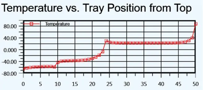
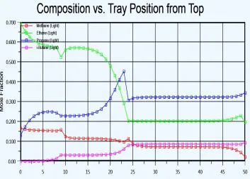
Fig 2 Deethanizer Tower (C102) Simulation Predicted Tray Vs Temperature Profile
In our simulation study, important material streams are summarized in TABLE III for quick reference. HYSYS requires the streams to be defined sufficient enough to predict rest of huge library of properties.
Table details the parameters used during the simulation in order to simulate C102 and C104 which are tray type distillation columns. Deethanizer (C102) simulation was first started. From other distillation columns in model palette of HYSYS, we have chosen the “reboiled absorber column” to simulate C102. The dimension of tower is specified in the “rating” tab of column environment, we found the residence time of 60 seconds. Tray spacing was also selected to be 1.804 ft, diameter of tower was 3.937 ft and weeping factor was fixed to be 1.0. Other feed data was top and bottom pressure and temperature, pressure drop, direction of flows and duty of reboiler, we are left one more job to do; and that is specifying the degree of freedom for this tower in “monitor” tab. When mentioning the degree of freedom, column was not solving by specifying the value of Reflux rate, bottom production rate, ethane value in top product, duty of reboiler, propane slippage in top stream or even mentioning the overhead temperature of tower. Finally column converged on specifying the value of bottom temperature of 80 °F. Temperature Vs Tray profile is mentioned in Fig 2 Deethanizer Tower (C102) Simulation Predicted Tray Vs Temperature Profile.
At this convergence, parameters were compared with real plant data and found satisfactory matching. In the parameter > Estimates tab we got the tray wise composition of each component in gas which is otherwise difficult to be calculated. HYSYS also provides the flexibility of specifying the efficiency at each tray (total trays are 50 in number). Another useful tool in solving this column was option of selecting the number of iterations to solve the column in parameters > solver tab. Here we have also selected the “fix damping factor” of 1. Solving method for this C102 was “modified HYSIM inside-out”.
Debutanizer (C104) is also simulated then. In model palette of HYSYS, we have selected the standard “Distillation column” to simulate C104. The dimension of tower is specified in the “internals” tab of column environment, we found the residence time of 60 seconds. Sieve type trays were selected from many available types of other trays used in industry. Tray spacing was also selected to be 1.804 ft, diameter of towDer was 4.921 ft and weeping factor was fixed to be 1.0.
430
©IJRASET: All Rights are Reserved
TABLE IV
Parameters of towers C102 and C104 used in simulation
Name Deethanizer (C102) Debutanizer (C104)
Number of Trays 50 50
Type of Tower Distillation Tower with Reboiler Distillation Tower with Reboiler
Internal Type Valve Type Trays Valve Type Trays
Diameter [ft] 3.937 4.921
Tray Spacing [ft] 1.804 1.804
Tray Volume [ft3] 21.97 34.32
Weeping Factor 1.0 1.0
Tray Hold up [ft3] 3.12 3.12
Feed from Expander Tray # 10 Tray # 14
Pressure (psig) 229.7 230
Reboiler Pressure (psig) 232.7 235
Stage Efficiency 0.7 (Overall) 1.0 (Overall)
Solving Method Modified HYSIM Inside-Out Modified HYSIM Inside-Out
Damping Fixed Fixed
Reboiler Duty [MMbtu/hr] 0.279300 0.4956
Reflux Ratio 0.072 1.214
Boil up Ratio 0.1504 2.554
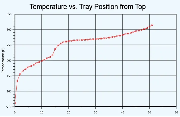
[image:6.612.35.567.96.380.2]Finally column converged on specifying the value of bottom temperature of 315 °F and specifying the residue in LPG of 5% which is amount of residue in real plant LPG also. Temperature Vs Tray profile is mentioned Fig 3.
Fig 3 Debutanizer (C104) simulation predicting the temeprature on trays of column
[image:6.612.135.489.417.648.2]431
©IJRASET: All Rights are Reserved
Turbo Expander was then simulated in the HYSYS, where we can find the dedicated unit operation for expander in model palette. This was selected and data was fed according to the dimension of actual expander at plant. Curve input method was selected as single curve. Important condition mentioned for our simulation was delta P, pressure difference of 522 psig. Outlet temperature was mentioned as -114 °F which is actual temperature at plant. Third parameters that need to be mentioned in order to get expander converged at HYSYS was flow rate passed from feed stream to be 11.11 MMSCFD. We found the adiabatic efficiency to be 61.87 and polytropic efficiency to be 59.412. Power produced was 187 hp which is being transferred to compressor K101 as this is basically turbo expander in which a common shaft is holding both expander and compressor at each end. Further results and discussions are summarized in results section.
Gasoline separated in C104 is recycled back to expander inlet in order to enhance the NGL recycling. This can be done in HYSYS by selecting a material stream and connecting it with gasoline flowrate stream at downstream of C104 and inserting a “Tee” from model palette. Using “Tee” unit operation we can divide this gasoline stream in to two material streams. One is going into storage tanks for gasoline while other is recycle back to inlet of expander. We can also select the flow rate of each stream or ratio of amount of gasoline going in each stream. We have also inserted a pump unit operation here. Pump can be selected from model palette also. This pump was placed on recycled line to pump the NGL to V103 upstream.
Important tool that we need to use here was “recycle” logical unit operation. This tool adjusts the downstream unit within the selected tolerance according to assumed value.
V. RESULTSANDDISCUSSIONS
Simulation was successfully converged and checked with actual running parameters. Following are the discussions for each section:
A. Material Streams
The different material-streams with respective operation parameters are listed below in the Error! Reference source not found., Error! Reference source not found. and Error! Reference source not found.:
TABLE V
Material streams depicted by HYSYS
Name Feed To
K10 1 To E10 7 To E10 4 To V101 OVH D To V103 To Expa nder To V104 VAP 104 To E102 To V109 LPG Pressure
[psia] 610 610
784. 8
774.
8 769.8 764.1 757.1 757.1 234.7 234.7 228.7 226.7 230
Temperature
[F] 95 95
134.
2 125 89.1 80 -40 -36.6 -114 -114
-103.7 124 61.5
Molar Flow
[MMSCFD] 13 13 13 13 13 13 13 11.11 11.11 10.54 11.96 11.96 0.889
Std Ideal Liq Vol Flow [BPD]
5743 5743 5743 5743 5743 5743 5743 4693 4693 4368 5018 5018 598.1
Molecular Weight 19.8 1 19.8 1 19.8 1 19.8
1 19.81 19.81 19.81 17.76 17.76 17.03 17.35 17.35 43.84
Mass Enthalpy [Btu/lb] -1759 -1759 -1742
-1747 -1769 .1773
-1874 -2010 -2010 -2055 -2025 -1903 -1212
Mol Density [lbmol/ft3] 0.11
0.11 6
0.13 9
0.14
432
[image:8.612.133.434.87.605.2]©IJRASET: All Rights are Reserved
Fig 4 Screen shot of simulation
B. Performance of Deethanizer (C102)
433
©IJRASET: All Rights are Reserved
TABLE VI
Key performance indicator of Deethanizer
Propane mol % around Deethanizer Tower
Stream Name Value [mol%]
C3 in Feed stream to Tower 1.4
C3 in Residual Gas stream at Downstream of Deethanizer 0.35
C. Performance of Deethanizer (C102)
[image:9.612.127.478.87.196.2]Key performance indicator for Debutanizer tower (C104) is amount of residue in LPG. This residue consists of mainly Pentane and traces of heavier [21]. Dropping the temperature of tower bottom may lead to condensation of more Butane while increase in tower re-boiler temperature may lead to increase in Pentane (residue in LPG). Optimum temperature was sorted out using HYSYS 10 and summarized as follows in TABLE VII:
TABLE VII
Key Performance indicator in Debutanizer
Residue in LPG [mol %] (Residue = mol % of i-Pentane + N-Pentane)
Feed stream to Debutanizer 13.5
LPG stream 5
Raw Gasoline stream at downstream of
Debutanizer 60.74
Propane and Butane comprise the LPG and are extracted from Debutanizer top while Pentane and heavier are taken from Tower bottom. Tray wise profile of this composition is simulated in Fig 5
[image:9.612.171.443.283.418.2] [image:9.612.132.485.462.714.2]434
©IJRASET: All Rights are Reserved
D. NGL Recycle Stream
[image:10.612.177.435.175.455.2]Gasoline separated at downstream of debutanizer can be recycled back to Deethanizer feed stream before expander (i.e at inlet of V103). The purpose of stream is enhancing Propane recovery in Deethanizer tower by creating absorption effect. It increase the flow rate of down comers and captures increased amount of Propane slipping with vapors in overhead stream of Deethanizer consisting mainly of Residual gas (Methane and Ethane). TABLE VIII shows the process parameters for this stream in HYSYS.
TABLE VIII
HYSYS conditions of NGL recycle stream
Parameters Value
Liquid Phase 1.0
Temperature [F] 100.3
Pressure [psig] 757.1
Molar Flow [MMSCFD] 0.1007
Mass Flow [Tonne/D] 9.056
Standard Ideal Liquid Vol Flow [bpd] 88.76
Heat Flow [btu/hr] -7.5E4
Composition of NGL stream (mol %) by HYSYS
Methane 0.0
Ethane 0.0
Propane 0.0
i- Butane 0.0001
n- Butane 0.0253
i- Pentane 0.3755
n- Pentane 0.2654
Hexane and higher 0.3336
CO2 0.0
N2 0.0
H2O 0.0
[image:10.612.69.550.515.648.2]After converging the stream in HYSYS, parameters are deduced by running case studies in which different flow rate of recycle stream are simulated and Propane slippage is studied at Deethanizer overhead.
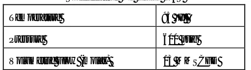
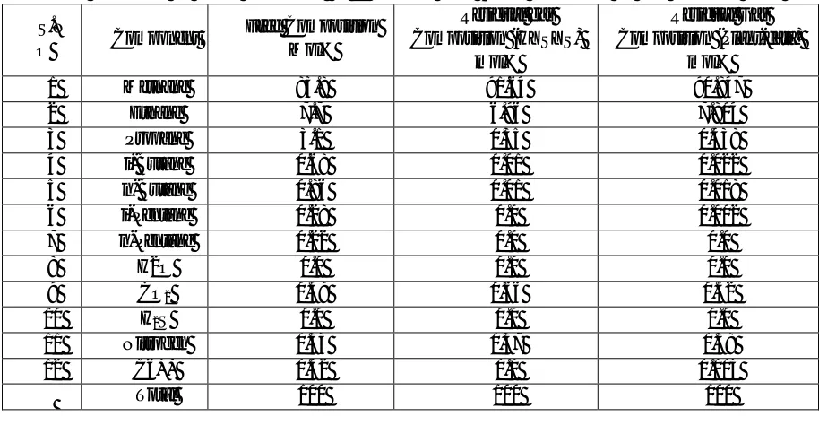
TABLE IX
Case study performed in HYSYS for optimimum flowrate of NGL recycle stream
TABLE IX shows case study was developed for NGL Recycle stream (see Error! Reference source not found.) at different flow rates of recycle stream and observing the Hydrocarbon Dew point (HCDP) of Sale gas (Residual Gas). Total flow rate of NGL stream from bottom of Debutanizer is 180.4 BPD. Above table shows the impact of recycling of NGLs at inlet of Expander. Although LPG production (0.9 MTon increased) and HCDP are improving in terms of our objective but at the cost of increased HP of Expander. At the flow-rate of 25.09 Barrel/Day (Case 3) Work done (HP) of Expander remained almost unaffected hence, this is our optimum flow rate of recycling of NGL stream back to Expander Inlet. Increase in LPG is 0.25 MTon / Day (2.88 Mton / Year).
Flow Rate (bpd)
Hydrocarbon Dew Point of Residual gas
(F)
LPG (Mton/Day)
HP of Expander (GE101)
Case 1 0.0 -81.08 45.78 167
Case 2 11.44 -81.10 45.89 168
Case 3 25.09 -81.16 46.02 168
Case 4 41.94 -81.22 46.16 178
Case 5 62.89 -81.30 46.38 182
435
©IJRASET: All Rights are Reserved
E. Simulation Model Validation
Simulation model was developed with Aspen HYSYS 10 simulation software and compared with real time plant parameters of running plant in Pindigheb distt, Pakistan. Conditions and composition of the feed are given in Table 1 and 2. The model was simulated for LPG Recovery plant using turbo expander technology. The LPG plant is feed with temperature around 110°F while pressure of 600 psig. M/s Aspentech HYSYS 10 was used then to simulate plant which removed the Propane and heavier hydrocarbon from Natural gas, minimizing the HCDP and making it saleable in clients pipeline net work (M/s SNGPL, Pakistan in this case). The composition of sale gas is shown in Table below(Error! Reference source not found.). On the other hand, this table also compares the composition data of Sales gas of real plant.
[image:11.612.77.534.253.490.2]Inspecting the data in the Table 18 results are matching within accuracy of +-9.1% for both the real running parameters and HYSYS simulation parameters. That means that Aspentech HYSYS results are in good approximation with the real plant process data.
TABLE X
Model Validation Of Hysys Simulation By Comparing With Actual Parameters Of Lpg Recovery Plant
S.N
O Component
Feed Composition Mol%
Residual gas Composition (HYSYS)
mol%
Residual Gas Composition (Plant-data)
mol%
1 Methane 85.8 91.64 90.847
2 Ethane 7.7 6.96 7.804
3 Propane 3.1 0.35 0.438
4 i-Butane 0.68 0.01 0.022
5 n-Butane 0.86 0.01 0.018
6 i-Pentane 0.28 0.0 0.002
7 n-Pentane 0.22 0.0 0.0
8 H2O 0.0 0.0 0.0
9 CO2 0.49 0.66 0.52
10 H2S 0.0 0.0 0.0
11 Nitrogen 0.33 0.37 0.38
12 C6+* 0.42 0.0 0.005
Total 100 100 100
VI.CONCLUSIONS
In this study a simulation model of LPG recovery plant is developed. Simulation result is compared further with running plant recovering LPG from natural gas at Attock, Pakistan. Process conditions are optimized to maximize the production of LPG as well as reduce the HCDP of residue gas.
Aspen HYSYS V10 is useful simulation tool in predicting the complex interaction of Hydrocarbon at gas treating facility and works close to accuracy for the Process people to perform the project activities. It is accommodating in:
1) When trouble-shooting the actual plant operating condition in comparison with the optimized-with-simulation plant results.
2) Decrease in Propane slippage in Residual gas (Sale gas) with the help of recycling NGL back to Expander inlet for showering from top of Deethanizer. HCDP of sale gas also decreased which was aim of this simulation model.
436
©IJRASET: All Rights are Reserved
VII. ACKNOWLEDGMENT
Authors wish to acknowledge University of Engineering and Technology, Peshawar in Pakistan, M/s Pakistan Oilfields Limited and other contributors for developing and maintaining the this study which have been used in the preparation of this paper.
REFERENCES
[1] (2008) Principles of Hydrocarbon Dew Point," Dew Point Control, [Online]. Available: https://www.dpc.com/resources/hcdp/ [2] (2008) NGL/LPG Recovery and Fractionation," Siirtec Nigi, [Online]. Available: https://www.siirtecnigi.com/design-ngl-lpg-recovery
[3] K. Muralikrishna, M. V.K.P and S. S.S, "Development of Dividing Wall Distillation Column Design Space for a Specified Separation," Chemical Engineering Research and Design, vol. 80, no. 2, p. March, 2002
[4] (2008) A. Kaaeid, Lokhandwala and M. Jacobs, "New Membrane Applications in Gas Processing," Membrane Technology & Research, [Online]. Available: https://www.mtrinc.com/wp-content/uploads/2018/09/GPAATLANTA_NG01.pdf.
[5] (2008) H. D. Jacoby, J. M. Reilly, J. McFarland and S. Paltsev, "MIT Joint Program on the Science and Policy of Global Change," July 2004. [Online]. Available: http://web.mit.edu/globalchange/www/MITJPSPGC_Rpt111.pdf
[6] (2018) Global Gas Flaring Reduction Partnership (GGFR)," The World Bank, [Online]. Available:
https://www.worldbank.org/en/programs/gasflaringreduction
[7] (2018) Natural Gas," Wikipedia The Free Encyclopedia, 2 6 2013. [Online]. Available: https://en.wikipedia.org/wiki/Natural_gas
[8] J. Bullin, C. Fitz and T. Dustman, "Practical Hydrocarbon dew point specification for natural gas transmission lines," Bryan Research & Engineering, LLC,
vol. 1, p. 3, 2006.
[9] (2018) Principles of Hydrocarbon Dew Point," Dew Point Control, [Online]. Available: https://www.dpc.com/resources/hcdp/. [10] Data from Gas chromatograph at residual gas, Plant literature and log books, Rawalpindi: Pakistan Oilfields Limited, 2018. [11] C. Alexander and B. Horace, "Production or recovery of lighter hydrocarbons". United States Patent US1813024A, 7 7 1931
[12] LPG Prices," Oil and Gas Regulatory Authority OGRA, [Online]. Available: http://www.ogra.org.pk/lpg-notified-prices. [Accessed 2 8 2018].