Comparative Analysis of Energy Consumption and
Cost of Different Air Conditioning Systems for
Commercial Building
Shaik Saber1, Raza Ahmed Khan2 1, 2
Nawab Shah Alam Khan College of Engineering and Technology,India
Abstract: The quick ascent in temperature because of an Earth-wide temperature boost and environmental change has raised worries over the ecological effects. These impacts can have significant consequences for the indoor condition. Climate changes will influence different aspects of the indoor condition and in addition the partners of that indoor condition. Buildings will require less heating in the winter and additional cooling in the summer, bringing about an increased utilization of Ventilation and cooling system. In the present situation significance of Air Conditioning and Ventilation systems plays a significant part in giving comfort conditions to the inhabitants of building. With developing threats of global warming and green house gas emissions, the need for equipment selection is very much important which impacts energy consumption, the initial cost of installation, and there by recurring operating and maintenance costs. The main objective of the present project is to evaluate energy consumption of HVAC System for a large commercial building with two major air conditioning methods which are Chiller air conditioning system and variable refrigerant flow air conditioning system. The task of design of a building is conducted by estimating the cooling load requirement, selection of equipment based on the use of areas inside building, to evaluate the energy consumption of HVAC equipments and net energy savings.
I. INTRODUCTION
Air conditioning system configuration is a sub train of mechanical designing, in light of the standards of thermodynamics, liquid mechanics, and heat exchange. Heating, Ventilating and Air Conditioning, (HVAC) is a tremendous field. Central air systems incorporate a range from the simple system to complex systems, utilized for comfort cooling and heating, to a great degree solid aggregate ventilating and cooling systems found in submarines and air transports. Cooling differs from the little local unit to refrigeration machines that are 10,000 times the size, which are utilized as a part of modern procedures. Contingent upon the multiphase nature of the necessities, the HVAC designer must consider numerous of issues than just keeping temperatures agreeable. The expression "ventilating and cooling" has bit by bit changed from significance simply cooling to the aggregate control of Temperature, Moisture noticeable all around (stickiness), Supply of outside air for ventilation, Filtration of airborne particles, Air development in the involved space. These are principal ideas that are utilized by originators to settle on choices about system outline, activity, and upkeep. Central air (meaning for Heating, Ventilation and Air Conditioning) makes an atmosphere that takes into consideration greatest solace by adjusting for evolving conditions. The reason for HVAC configuration is to keep up both high indoor air quality and comfort conditions for occupant to work. These double contemplations require incorporated outline effectiveness or configuration approach. (Central air) hardware needs a control system to direct the activity of a heating and cooling system with large coverage area and energy saving.The three elements of heating, ventilation, and cooling are interrelated, particularly with the need to give warm solace and adequate indoor air quality inside sensible establishment, activity, and upkeep costs. Central air systems can give ventilation, decrease air infiltration, and keep up weight connections between spaces. Central air is a vital piece of private structures, for example, structures, lodgings and living offices, medium to extensive modern and places of business, for example, high rise building, locally available vessels, and in marine situations, where protected and sound conditions are managed as for
A. Maintaining indoor air quality (expulsion of waste vapor)
B. maintaining inside room temperature (acquires cool air and exhaust hot air)
C. Remove humidity (get drier air and fumes wet air)
The development of the segments of HVAC systems ran as an inseparable unit with the mechanical and new strategies for modernization, higher proficiency, and system control are always being presented by organizations and innovators around the world.
II. OBJECTIVES OF THE PROJECT
A. Selection of reasonable HVAC system for the proposed multi story building.
B. Cooling Load calculations utilizing E20 Excel sheet
C. Detailed Design of HVAC system, for example, Ducting and piping.
D. Evaluate the Energy utilization of HVAC systems for different HVAC systems
E. To make bill of materials and assess cost of the systems.
F. To show the performance of different air conditioning systems.
III. PROJECT METHODOLOGY
A. Conducting a study and exploring the related contextual investigations, distributed universal papers, related to ASHRAE.
B. Selection of HVAC system in view of the measure of the building and Energy productivity.
C. Equipment determination according to ASHRAE measures.
D. HVAC system configuration utilizing HAP, diverse ideas and ASHRAE, SMACNA measures for finish plan of the HVAC system according to codes.
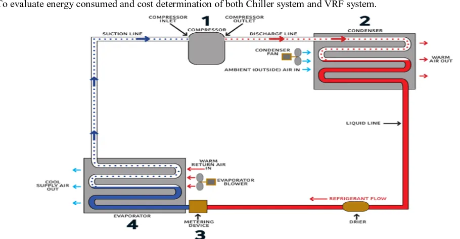
[image:2.612.62.517.316.553.2]E. To evaluate energy consumed and cost determination of both Chiller system and VRF system.
Figure -1 Schematic Diagram Of How An Air Conditioning System Work
IV. TYPES OF HVAC SYSTEMS
A. Different Types Of Hvac Systems 1) Window Air conditioners
2) Split Air Conditioners (through the wall air conditioners)
3) Unitary / Packaged air conditioners
4) VRF / VRV Air conditioners
5) Chiller Central Air-conditioning system (Air / Water Cooled)
B. Vrf / Vrv Air Conditioners
VRFs are typically installed with an Air conditioner inverter which adds a DC inverter to the compressor in order to support variable motor speed and thus variable refrigerant flow rather than simply perform on/off operation. By operating at varying speeds, VRF units work only at the needed rate allowing for substantial energy savings at load conditions. VRFs come in two system formats, two pipe and three pipe systems. In a heat pump two pipe system all of the zones must either be all in cooling or all in heating. Heat Recovery (HR) systems have the ability to simultaneously heat certain zones while cooling others; this is usually done through a three pipe design, with the exception of Mitsubishi and Carrier, whose systems are able to do this with a two pipe system using a branch circuit (BC) controller to the individual indoor evaporator zones.
Figure-2 A Typical VRF/VRV Air Conditioner System
1) Advantages of VRF/VRV Air Conditioners:
a) VRF systems are suited to any building where there are countless rooms to be aerated and cooled.
b) Variable refrigerant stream (VRF) system has capacity to react to variances in space stack conditions
2) Disadvantages of VRF/VRV Air Conditioners:
a) The cooling limit accessible to an indoor unit area is diminished at bring down open air temperatures. This constrains the utilization of the system in chilly atmospheres to serve rooms that requires year around cooling, for example, Telecom rooms.
b) The outer static weight accessible for ducted indoor areas is restricted. For ducted indoor areas the permissible ventilation work lengths and fittings must be kept to a base. Ducted indoor areas ought to be set close to the zones they serve
C. Central Air-Conditioning System
Figure-3 A Typical Central Chilled Water Air Conditioning System
V. HVAC SYSTEM DESIGN
A. Description of Building
The building considered in this Project is a Five story building located in Vijayawada, Andhra Pradesh in the south of India. The floor area of the building is 13,000 sq ft and its floor to floor height is 15 ft. with total floor area of above 65,000 sq ft. Each Floor has specific use. The walls of the building consist mainly of brick and plaster without any insulation. The roof consists of 125mm concrete block and without insulation. The windows are dotted plane with a shading coefficient of 1.0 is considered. The HVAC systems used in the building is VRF system one for each zones on each floor.
Table-1 Description Of Proposed Building
Characteristics Description of the Base Case
Location Vijayawada, Andhra Pradesh
Orientation Front Elevation facing East
Plan Shape Rectangle
Number of floors B+G+4
Floor to Floor Height 12 FT
Floor Area 5300 sqft
Type of Glass Plane dotted glass 4mm
Solar Absorbance (for Exterior Surfaces) 0.6
Exterior Walls 9” thick Brick walls
Roof 6” mm Concrete slab
Floors 5
Lighting Power Density Working Area 1.5 w/sft
Infiltration 0.5 ACH
System Type VRF System or Chilled water system
Thermostat Setting 75 degree F
VI. COOLING LOADS CALCULATIONS
Cooling Loads Classified by Source Cooling loads fall into the accompanying classifications, in view of their sources:
A. Heat exchange (increase) through the building skin by conduction, because of the outside indoor temperature difference.
B. Solar heat gain (radiation) through glass or other straightforward materials.
C. Heat gain from ventilation air as well as penetration of outside air.
D. Internal heat picks up produced by inhabitants, lights, apparatuses, and hardware.
1) Heat Load Calculations: The space cooling load is the rate at which heat should be expelled from the space to keep up a steady air temperature. To figure a space cooling load, gritty outline parameters are required.
The plan premise regularly incorporates data on
a) Geographical site conditions (scope, longitude, wind speed, precipitation and so on.)
b) Outdoor plan conditions (temperature, mugginess and so forth)
c) Indoor plan conditions
d) Building attributes (materials, size, and shape)
e) Configuration (area, introduction and shading)
f) Operating timetables (lighting, inhabitance, and equipments)
g) Additional contemplations (sort of ventilating and cooling system, fan energy, fan area, conduit heat loss and pick up, sort and position of air return system…)
VII. RESULTS
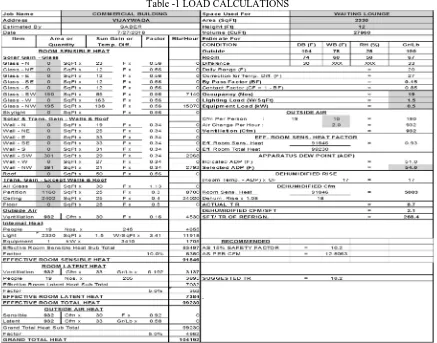
[image:5.612.88.525.382.725.2]The total heat load for the whole project was calculated and it was found to be 204 TR with the help of E-20 sheet, cooling loads are calculated using E20 sheets. Sample sheet is as shown:
A. HAP Software Energy Simulation Results
Table-2 HAP Chilled Water Plant Simulation Results
Month
Cooling Coil
Load
(kWh)
Plant Load
(kWh)
Chiller
Output
(kWh)
Chiller Input
(kWh)
January 44588 44588 44588 16090
February 58440 58440 58440 22138
March 91377 91377 91377 39211
April 111556 111556 111556 52046
May 134815 134815 134815 66935
June 127103 127103 127103 55717
July 109432 109432 109432 42437
August 99326 99326 99326 37393
September 95090 95090 95090 36580
October 84207 84207 84207 32200
November 59904 59904 59904 22035
December 43405 43405 43405 15576
Total 1059244 1059244 1059244 438359
Table-3 VRF System Simulation Results Ground Floor
Month
Terminal
Cooling Coil Load (kWh)
Terminal
Cooling Eqpt Load (kWh)
Terminal
Unit Clg Input (kWh)
January 17613 17613 3334
February 19486 19486 3987
March 25341 25341 5923
April 27436 27436 7030
May 30704 30704 8449
June 27670 27670 7009
July 24063 24063 5462
August 22410 22410 4930
September 22590 22590 5024
October 23328 23328 5003
November 20723 20723 4111
December 17941 17941 3363
Table-4 VRF System Simulation Results First Floor Month Terminal Cooling Coil Load (kWh) Terminal Cooling Eqpt Load (kWh) Terminal
Unit Clg Input (kWh)
January 7486 7486 1857
February 10292 10292 2695
March 17232 17232 5047
April 21679 21679 6802
May 26294 26294 8791
June 25763 25763 7824
July 22376 22376 6068
August 20401 20401 5364
September 18744 18744 5041
October 15559 15559 4130
November 10289 10289 2620
December 7187 7187 1774
Total 203302 203302 58011
Table-5 VRF System Simulation Results second Floor (typical )
Month Terminal Cooling Coil Load (kWh) Terminal Cooling Eqpt Load (kWh) Terminal
Unit Clg Input (kWh)
January 14891 14891 3227
February 17653 17653 4076
March 25667 25667 6667
April 30213 30213 8487
May 35368 35368 10604
June 33157 33157 9099
July 29664 29664 7302
August 27588 27588 6590
September 26281 26281 6390
October 23906 23906 5697
November 18063 18063 4071
December 14463 14463 3112
Total 296914 296914 75322
VIII. CONCLUSION
HVAC System design of the commercial building is designed for VRF and Chilled water system to evaluate the energy consumption and cost evaluation. The Energy consumption of the building is evaluated using HAP 4.51 Software. It is found that the Annual net cooling energy consumption of the building for a VRF System is 347,601 kWh, and for a chilled water system is 438,359 kWh.
Table-6 Energy consumption of VRF System Floor Energy Consumption kWh
Ground Floor 63,624
First Floor 58,011
Second Floor – Typical 3 floors 75,322
Total 347,601
The Net capital investment of chilled water system and VRF system is evaluated. The net capital expenditure of chilled water system is Rs 1, 66,82,500. And for vrf system is Rs
1,20,93,050. The net savings in the capital investment if VRF system is used is rupees 45,89,450 which accounts to 27.51 % capital savings.
REFFERENCE
[1] Carrier handbook, mcgraw-hill publishing company 1965. [2] Ashrae handbook, 2001 fundamentals applications. [3] Hvac design manualby james e.brombaugh. [4] Refrigeration and air-conditioning [5] Smacna design manual