Abstract—This paper presents a novel design concept, in which a hybrid power interface system (HPIS) is constructed to work smartly in various micro-grid (MG) operations. Some distributed generation (DG) systems, e.g., the wind turbine generator (WTG) and the Photovoltaic (PV) systems conventionally generate real power based on natural conditions thus the average utilization rate of the entire asset is normally low. To eliminate this shortcoming, the proposed HPIS aims to use the DG inverter system optimally. To achieve a cost-effective design, a three-leg zigzag transformer is incorporated into the proposed HPIS to maximize the operating capability of DG inverter in terms of real power regulation, active power filter (APF) functions for current harmonics compensation and reactive power compensator for MG voltage support and power factor correction. The HPIS is designed to fully utilize the DG inverter capacity after performing various real power control functionalities required by the system operator. In this paper, the mathematical model of HPIS and its related controllers designed in two-axis stationary reference frame are firstly addressed. Then, simulation studies on a simplified MG network are carried out and followed by a set of experimental tests on dSPACE1104. Typical results are presented with brief discussions to demonstrate the feasibility and effectiveness of the proposed control scheme.
Index Terms—hybrid power interface system (HPIS), distributed generator (DG), micro-grid (MG), active power filter (APF)
I. INTRODUCTION
OWER converter interfaced distributed power generations (DG), renewable energy resources (RES) based micro-grids (MG) and state-of-the-art communication and control technologies have been recognized to play an important role in the achievement of some energy policies set by Taiwan’s government. The goal of these energy policies include reductions in high-polluting power generations and global greenhouse gas emissions, improved diversity and security of energy supply, and exploitation of possible incentives for creating local value added opportunities for the related industrial sectors in Taiwan. Based on the related technical reports from the open literature, potential RES based power generations may include wind turbine generator (WTG)[1], photovoltaic (PV)[2], and fuel cell (FC)[3]. Of these power generating methods, the interests in PV energy is
Manuscript received December 8, 2012, accepted January 6, 2013. This work was supported in part by the National Science Council of Taiwan, R.O.C. through: NSC 101 - 2221-E -239-031.
Tsao-Tsung Ma and Tzung-Han Shr are with the Electrical Engineering Department, National United University, Miao-Li City 36003, TAIWAN, R.O.C. (phone: 886-37-381369; fax: 886-37-327887; e-mail: [email protected]).
growing worldwide, with annual growth rate of 25-35% over last ten years. It is recorded about 25 GW of total commercial PV installations at the beginning of 2012 and the increasing trend of using PV still continues. Although the PV generation system is still expensive, according to recent published reports, PV prices have dropped by 45% over last two years and further drop is expected in the near future [4]. In fact, a number of different PV incentive programs have been introduced in Taiwan since 2008. With the same objectives, some of developed countries are currently promoting residential and commercial uses of PV generation systems [5]-[7]. Based on the standards such as IEEE1547, IEEE 929 and UL1741, PV inverter systems should operate at unity power [8]; however, this regulation has some limitations in practical applications. It has been proved that with proper design of the controllers these inverter systems working as the power interfaces in WTG, PV and FC all have the capability to provide additional control functions in addition to the regulation of real power generated from various RES. Intrinsically, some DG systems, e.g. the wind turbine generator and the PV system generate real power based on weather conditions thus the average utilization rate of the entire asset is normally low. This has resulted in that the payback time period for the system owners becomes longer. To make the best use of the DG hardware systems, the concept of utilizing PV inverter as a reactive power controller during the night time for voltage control thereby increasing the connectivity of a nearby wind farm, is proposed in [9]. A number of potential operations of a 3-phase PV grid connected inverter are discussed in [10], [11]. Some similar examples regarding reactive power compensation and voltage support in MG are also illustrated in [12], [13]. However, in the above published papers, only individual control function has been included in the operation of DG inverters.
This paper proposes a novel design concept concerning the feasibility of performing multiple control functions in the DG inverter system working in micro-grids. To achieve a cost-effective design, a three-leg zigzag transformer, designed for eliminating the triplen current harmonics of the local nonlinear loads, is incorporated into the proposed HPIS to maximize the operating capability of DG inverter. With the proposed design concept the DG inverter is able to optionally utilize the unused portion of rated capacity after performing the function of real power generation. It is important to note that to verify the feasibility of the design concepts, the proposed HPIS system with dSPACE1104 as the main controller has been practically constructed in the laboratory of applied power electronics research group (APERG), National United University, Taiwan.
Design of a Cost-Effective Power Interface for
Advanced Micro-grid Operation and Control
Tsao-Tsung Ma, Member, IEEE and
Tzung-Han Shr
II.THE FIRST MICRO-GRID TEST BED IN TAIWAN
Distribution systems possessing DGs and controllable loads with the ability to operate in both grid-connected and standalone modes are an important class of the so-called MG power systems [14]-[15]. A typical MG system constructed by the Institute of Nuclear Energy Research (INER) in Taiwan is shown in Fig. 1[16]. As can be seen in Fig 1, the INER micro-grid with a designed maximum capacity of 475.5 kVA has three independent Zones. In Zone1, there is a 31.5 kVA PV, a 65 kVA microturbine, a total of 60 kVA controllable load bank, a 150kVA wind turbine and a 100 kVA ABB PCS-100 BESS. Zone2 has a 60 kVA PV system, a 65 kVA microturbine and a total of 60 kVA controllable load bank. Zone3 is equipped with a 4 kW small wind turbine, a 25 kVA wind turbine, a 10 kVA PV, a 65 kVA microturbine and a 30 kVA controllable load bank. To facilitate possible tests considering the conditions of practical operating modes, Zone 2 and Zone3 are connected in series, while Zone 1 and Zone2 are in parallel.
It is well known that MG strives for optimized operation of the aggregated distribution systems by coordinating the various DGs, ESS and load resources not only when connected to the distribution system but also in a standalone mode. In either modes of operation, advanced local controls, energy management, power quality and protection technologies are required for robustness and reliability. In practice, the energy management optimization objective function can be tailored to the needs of each application. In a practical MG project, the overall objective is to optimize operating performance and cost in the normally grid-connected mode, while ensuring that the system is capable of meeting the performance requirements in standalone mode. To satisfy the needs of possible applications, some ESS units are inevitably required. In the INER MG project, two ESS are to be installed to achieve some advanced operations and power management functions.
INER MG
SCC 1714 .2MVA X/R 8.02
69kV TPC 11.4kVINER Power System
10 MVA 7.26%
500 kVA 3.85% GCB Cable 2.5km
B0 ACB B1 NC
SSNC B2
380 V Micro -Grid
?T L1 L2
ABB
U NC
NC NFB
DMSC 100 kVA
480V 65kW 30kW 30kW
B3 L NC
380 V
4% 150kVA
380V B5
4% 150kVA inverter 12x3.6kVA
HCPV 21x1.5kW
B4 208V
PCS 100
L 30kW
L 30kW 400kVA 380V
150kVA ?T WT WT HCPV HCPV
inverter
380V 380V
inverter WT
25m 25m
30kW L 12x5kW 150kW 65kW 2x5kW 25kW 2x2kW
25m
Zone 2 Zone 3
Zone 1
NC
380 V
6x50kVAr
NUU VRB ESS 001
V_PCC P
Q Q
P IEEE 1547
UL1741 IEEE 929
SCC 1714 .2MVA X/R 8.02
69kV TPC 11.4kVINER Power System
10 MVA 7.26%
500 kVA 3.85% GCB Cable 2.5km
B0 ACB B1 NC
SSNC B2
380 V Micro -Grid
?T L1 L2 U
NC
NC NFB
DMSC 100 kVA
480V 65kW 30kW 30kW
B3 L NC
380 V
4% 150kVA
380V B5
4% 150kVA inverter 12x3.6kVA
HCPV 21x1.5kW
B4 208V L
30kW L 30kW 400kVA 380V
150kVA ?T WT WT HCPV HCPV
inverter
380V 380V
inverter WT
25m 25m
30kW L 12x5kW 150kW 65kW 2x5kW 25kW 2x2kW
25m
Zone 2 Zone 3
Zone 1
NC
380 V
6x50kVAr
NUU VRB ESS 001
V_PCC P
Q Q
P IEEE 1547
UL1741 IEEE 929
HPIS
[image:2.595.307.548.350.637.2]Harmonics
Fig. 1 System diagram of a typical micro-grid with various DG inverters (INER Micro-grid test bed, Taiwan).
III. HPIS PRINCIPLES AND CONTROL SCHEMES
A. HPIS Hardware Configuration
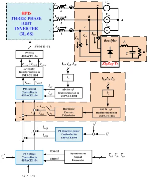
The operating principles and control concepts of the proposed HPIS are actually derived from the static synchronous compensator, a popular shunt-type FACTS device. In this paper, a basic HPIS hardware configuration which consists of a 3-phase switching converter using 6 IGBT switches, a three-phase zigzag transformer and a three-phase load bank including passive linear and nonlinear loads, as shown in Fig. 2 is chosen to introduce the proposed HPIS operating principles and its control schemes. The IGBT converter in the HPIS is designed to be operated from a DC link voltage provided by a PV or any kind of RES. In normal operations, the active power can be controlled in either direction between the AC terminals of the converter and the grid to regulate the DC voltage and thus the real power generation of the DG. In this hardware topology, the converter can also generate or absorb reactive power independently at its AC output terminals to affect system voltages or simply to act as a reactive power generator or an APF.
cona v vconbvconc
αβ
α
con v vconβ
β
o
i α
o i
αβ
s k
Q o
iα,
Q o
iβ,
*
Q Q
*
dc
V
( _ )
dc V P DG
t
ω sin
ωt cos
ab V VbcVca
h o
iα,
h o
iβ,
αβ
s k
1
S
2
S
Fig. 2 A simplified MG model with the proposed HPIS and control signals.
B. Functions of Zigzag Transformer in HPIS
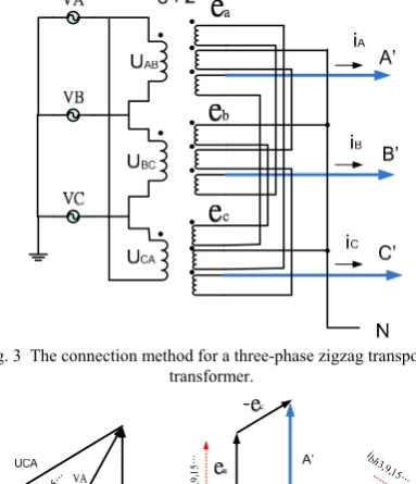
[image:2.595.49.291.505.750.2]HPIS more freedom in performing its real and reactive power flow control tasks, a zigzag transformer is incorporated into the HPIS for handling the triplen harmonics flowing in the MG distribution feeders. In the literature, a lot of research reports have proved that the zigzag transformer offers an attractive solution to harmonics problems. Typical solutions use a number of small zigzag transformers to isolate and reduce harmonic currents. Attractive features in using zigzag transformers can be summarized as: low system cost, easy to install, ability to reduce most harmonics current including the neutral, thus the size of neutral wires can be greatly reduced [17]. The connection method for a three-phase zigzag transposed transformer used in this study is depicted in Fig. 3. The relationship of voltage vectors between the primary and the secondary sides is shown in Fig. 4.
[image:3.595.80.272.239.462.2]Fig. 3 The connection method for a three-phase zigzag transposed
[image:3.595.330.551.386.574.2]transformer. 3, 9, 15 ... ah i 3,9,15 ... ch i 3,9,15... bh i 3,9,15 ... h i
Fig.4 The details of voltage vectors in a three-phase zigzag transposed transformer with the connection shown in Fig.3.
From Fig. 3 and 4, the following relationship can be derived.
' ' '
1 1 1
1 1 1
1 1 1
a b c A e B e e C ⎡ ⎤ − − ⎡ ⎤ ⎡ ⎤ ⎢ ⎥ ⎢ ⎥ ⎢ ⎥ ⎢ ⎥ = −⎢ − ⎢ ⎥⎥ ⎢ ⎥ ⎢ ⎥ ⎢− − ⎥ ⎢ ⎥ ⎣ ⎦ ⎣ ⎦ ⎣ ⎦ (1)
For a balanced three-phase system, the load currents of the zigzag transformer can be expressed as:
A B c
i i
=
=
i
=
i
(2)
IV. DESIGN OF HPISCONTROL SYSTEMS
In this paper, three important control functions are designed for the HPIS; i.e., real power regulation for DG, reactive power compensation for the grid and harmonic
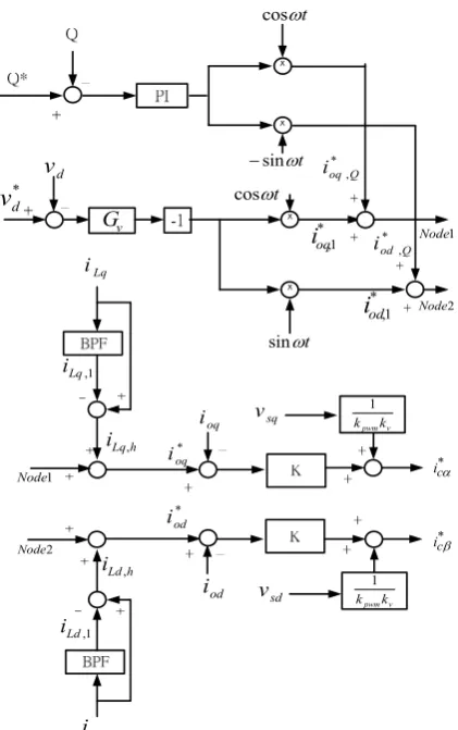
currents compensation for the local nonlinear load. These control functions can be activated simultaneously or individually. Because the proposed compensating requirements, i.e., real and reactive power or harmonic compensation, are directly related to the currents, shunt-type connection of DG inverter is a realistic topology as it normally injects currents at PCC. Therefore, this study uses the shunt-type connecting format for the implementation of HPIS control system shown in Fig. 2. With a number of mathematical manipulations, the output voltages and current commands of the HPIS can be obtained in two-axis stationary reference frame as briefly addressed below.
From Fig.2, the following voltage and current equations can be easily obtained on KVL.
⎪
⎪
⎪
⎩
⎪⎪
⎪
⎨
⎧
−
−
=
−
−
=
−
−
=
nN cn CN oC nN bn BN oB nN an AN oAV
V
V
dt
dI
L
V
V
V
dt
dI
L
V
V
V
dt
dI
L
(3) The above (3) can be rewritten into (4) and the equivalent forms in d-q frame as expressed in (5) and (6).) ( 1 2 1 2 1 2 1 1 2 1 2 1 2 1 1 3 2 ⎥ ⎥ ⎥ ⎦ ⎤ ⎢ ⎢ ⎢ ⎣ ⎡ − ⎥ ⎥ ⎥ ⎦ ⎤ ⎢ ⎢ ⎢ ⎣ ⎡ ⎥ ⎥ ⎥ ⎥ ⎥ ⎥ ⎦ ⎤ ⎢ ⎢ ⎢ ⎢ ⎢ ⎢ ⎣ ⎡ − − − − − − = ⎥ ⎥ ⎥ ⎥ ⎥ ⎥ ⎦ ⎤ ⎢ ⎢ ⎢ ⎢ ⎢ ⎢ ⎣ ⎡ cn bn an CN BN AN oC oB oA V V V V V V dt dI L dt dI L dt dI L (4) ⎥ ⎦ ⎤ ⎢ ⎣ ⎡ ⎥ ⎦ ⎤ ⎢ ⎣ ⎡ − ⎥ ⎦ ⎤ ⎢ ⎣ ⎡ ⎥ ⎦ ⎤ ⎢ ⎣ ⎡ = ⎥ ⎥ ⎥ ⎥ ⎦ ⎤ ⎢ ⎢ ⎢ ⎢ ⎣ ⎡ α β α β α β s s con con pwm o o v v v v k dt dI L dt dI L 1 0 0 1 1 0 0
1 (5)
⎥
⎦
⎤
⎢
⎣
⎡
⎥
⎦
⎤
⎢
⎣
⎡
−
⎥
⎦
⎤
⎢
⎣
⎡
⎥
⎦
⎤
⎢
⎣
⎡
=
⎥
⎦
⎤
⎢
⎣
⎡
α β α β α β s s con con pwm o ov
v
sL
v
v
sL
k
I
I
1
0
0
1
1
1
0
0
1
(6)Finally, the three-phase output current signals for the HPIS can be directly derived from (6) by using the inverse Clarke’s transformation.
the DC voltage of the HPIS or the real power of the DG if desired. To achieve a better dynamic performance, a feed forward compensating path is also used.
t ω
sin
− t
ω cos
*
,Q
oq
i
*
,Q
od
i *
d
v
d v
v
G
* 1 , od
i
* 1 , oq
i
t
ω cos
t ω
sin
Lq
i
Ld
i 1 ,
Lq
i
1 ,
Ld
i
h Lq
i ,
h Ld
i , *
oq
i
*
od
i
oq
i
od
i
v pwmk
k 1
v pwmk
k 1
*
c
iα
sq
v
sd
v
2
Node
1 Node
2
Node
1 Node
*
c
[image:4.595.64.275.95.431.2]iβ
Fig. 5 The signal block diagram of the derived HPIS controller.
V.CASE STUDIES AND RESULTS
To investigate the detailed dynamics of the proposed HPIS and to validate the proposed control method, simulations are carried out on a MG distribution network connected with a nonlinear DG link in Matlab/Simulink environment. It is considered that for the whole period of simulations the local loads are fed by the main source of the micro-grid feeder. In this study, during the simulation process active power which is delivered from DG link is assumed not activated. This assumption makes it possible to evaluate the capability of HPIS to track the fast change in the harmonic currents and the reactive current components of the reactive power required by the load or the grid independently. To simulate a realistic operation scenario in micro-grid network, the loads are connected and disconnected to MG distribution network randomly and the harmonic distortion of current waveform are calculated and compared in various conditions. Since the principle of proposed current control technique is based on separating active and reactive current components in stationary reference frame known as the two-axis components, in all conditions only phase-a parameters (voltage and current) are shown. To demonstrate the performance of the proposed HPIS to compensate total reactive power, load voltage, load current, source current and the output current of the HPIS are shown simultaneously.
In addition to the simulation cases for various control functions of the HPIS, in this paper, the proposed HPIS control scheme is further experimentally tested in a laboratory setup as shown in Fig. 6. In the experimental setup, a SPWM controlled three phase grid-connected inverter and a set of three-phase nonlinear load modules are used. Test conditions and parameters are the same as that used in simulation studies. All controllers except the SPWM circuit are implemented with dSPACE1104 control card on a PC. The sensed currents and voltages acquired to the dSPACE1104 and the control signals output to the SPWM circuit are using the AD/DA interfaces in dSPACE1104. The sampling frequency for data acquisition is set at 20 kHz to achieve satisfactory response. In this test, the DC voltage controlled at 400V with the three-phase 220V, 60Hz power grid.
Zigzag Power
Grid
Scope Power
Analyzer
Inverter Rectifier
Fig. 6 The experimental setup of the HPIS.
Case_1: Connection of nonlinear load link to the MG feeder with only zigzag transformer in operation.
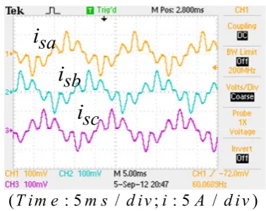
To test the effectiveness of a zigzag transformer in eliminating the triplen harmonics, a set of nonlinear load with three-phase balanced output currents are tested in this case. The results show that the third and its triplen harmonic currents contribute to the largest value of THD currents. In addition, the 5th, 7th, and 11th also give to the THD level; however, the amount is not significant. The decrease of the third and its triplen harmonic currents after the use of zigzag transformer is shown in Fig. 7 (a) to (e) for the balanced case. It is found that the THD current can be reduced about 40 % on the primary side (delta winding) of the zigzag transformer.
[image:4.595.315.534.615.756.2]2.1 2.15 2.2 2.25 2.3 2.35 2.4 2.45 2.5 2.55 2.6 x 10⁴
-5 -4 -3 -2 -1 0 1 2 3 4 5
t (1e-4s)
I(
A
)
La
i
Lb
i
Lc
i
(T i m e2.1 2.15 : 52.2 m s2.25 2.3/ d i v i2.35 ; : 52.4 2.45A2.5/ d i v2.55x 10)2.64
-5 -4 -3 -2 -1 0 1 2 3 4 5
t (1e-4s)
I(
A
)
La
i
Lb
i
Lc
i
(T i m e : 5m s / d i v i; : 5A / d i v)
(b) The current waveforms on the load side of zigzag transformer (simulation).
(
T i m e
: 5
m s
/
d i v i
; : 5
A
/
d iv
)
La
i
Lb
i
Lc
i
(
T i m e
: 5
m s
/
d i v i
; : 5
A
/
d iv
)
La
i
Lb
i
Lc
i
(c) The current waveforms on the load side of zigzag transformer (measured).
2.1 2.15 2.2 2.25 2.3 2.35 2.4 2.45 2.5 2.55 2.6 x 10⁴
-5 -4 -3 -2 -1 0 1 2 3 4 5
t (1e-4s)
I(
A
)
sa
i
sb
i
sc
i
(T i m e : 5m s / d i v i; : 5A / d iv)
(d)The current waveforms on the primary side of zigzag transformer (simulation).
(
T im e
: 5
m s d iv i
/
; : 5
A
/
d iv
)
sa
i
sb
i
sc
i
[image:5.595.61.258.57.193.2](e)The current waveforms on the primary side of zigzag transformer (measured).
Fig. 7 The current waveforms of the test with a balanced three-phase nonlinear load.
Case_2: Connection of nonlinear load link to the MG feeder with both HPIS and zigzag transformer in
operation.
In this test case, the HPIS link is connected to the network at t=0.0 s. At this moment a nonlinear load is added to PCC and it is removed at t=8.0 s. Fig.8 and Fig.9 respectively show the related voltages and currents in various HPIS control functions and grid operating conditions. As can be seen in Fig. 8 (a) and (b), after the connection of HPIS link to feeder the source current becomes sinusoidal since the harmonic currents are fully provided by the HPIS link. In Fig.9 (a) and (b), the nonlinear load is the same as that in previous case but the reactive power command of DG is set to 1000VAr to provide the demand of the grid. As shown in Fig.9, (c) and (d), when the command for the output reactive power of the DG is reversed there is a negative reactive power (-1000VAr) feeding backward to the HPIS link.
3.5 3.6 3.7 3.8 3.9
-3 -1 1 3
t(sec)
3.5 3.6 3.7 3.8 3.9
-5 -3 -1 1 3 5
t(sec)
3.5 3.6 3.7 3.8 3.9
-3 -1 1 3
t(sec)
(T im e: 8m s/d iv i; : 2A/d iv v; : 1 0 0V /d iv)
L a
i
H P I S ai
s a
i
s a
v
(a) Simulated results of voltage and current waveforms.
(Time: 5ms div i/ ; : 5 /A div v; :100 /V div) La
i
H PISa isa
i
sa
v
[image:5.595.339.518.286.429.2](b) Measured results on dSPACE1104 based hardware system . Fig. 8 The results of Case_2 when the HPIS is in operation.
7.5 7.6 7.7 7.8 7.9
-5 -3 -1 1 3 5
t(sec)
7.5 7.6 7.7 7.8 7.9
-5 -3 -1 1 3 5
t(sec)
7.5 7.6 7.7 7.8 7.9
-3 -1 1 3
t(sec)
(T im e: 8m s d iv i/ ; : 2A d iv v/ ; : 1 0 0V /d iv)
L a
i
H P I S a i
s a
i
s a
v
[image:5.595.77.266.587.736.2] [image:5.595.337.517.622.761.2](Time ms div i: 5 / ; : 5 /A div v; :100 /V div)
La
i
HPISai
sa
i
sa
v
(b) Measured results on APF function and a 1000 VAr reactive power command for HPIS.
5.5 5.6 5.7 5.8 5.9
-5 -3 -1 1 3 5
t(sec)
5.5 5.6 5.7 5.8 5.9
-5 -3 -1 1 3 5
t(sec)
5.5 5.6 5.7 5.8 5.9
-5 -3 -1 1 3 5
t(sec)
(T im e: 8m s d iv i/ ; : 2A d iv v/ ; : 1 0 0V /d iv)
L a
i
H P IS a is a
i
s a
v
(c) Simulated results on APF function and a -1000 VAr reactive power command for HPIS.
(
Time ms div i
: 5
/
; : 5 /
A div v
; :100 /
V div
)
La
i
HPISai
sa
i
sa
v
[image:6.595.78.267.60.210.2](d) Measured results on APF function and a -1000 VAr reactive power command for HPIS.
Fig. 9 The results of Case_2 when the HPIS is in operation with nonlinear load and a bilateral reactive power control.
VI. CONCLUSION
This paper has demonstrated a novel design of a flexible hybrid power interface system in which any DG inverter system can be utilized as an APF for harmonic currents compensation and a reactive power generator for power factor correction and voltage control at the PCC. It is important to note that decoupled current controllers are used in the functional control loops designed for the HPIS, better dynamic response can be achieved in various control functions performed by the proposed control algorithms. Based on comprehensive simulation studies with a simple
MG network carried out in Matlab/Simulink software environment and the hardware tests on dSPACE1104 controllers, the feasibility and effectiveness of the proposed HPIS concept incorporating the three-phase zigzag transformer to maximize the capability of DG inverters have been confirmed.
REFERENCES
[1] K.M. Syafii and M. A-A. Nor, Steady-State Wind Turbine Generation Model for Three-Phase Distribution Load Flow Analysis, IREMOS, Vol. 4 N. 2, April 2011 (Part B), pp. 772-777. [2] S. Arabi Nowdeh, B. Tousi, A. A. Zoraghchian and M. Hajibeigy,
Optimal PV and FC Application in a Hybrid Power System with the Aim of Selling Electrical Energy to Distribution Network,
IREMOS, Vol. 4 N. 5, October 2011(Part B), pp. 2392-2401.
[3] S. Aghajani, I. A. Joneidi, M. Kalantar and V. Mortezapour, Modeling and Simulation of a PV/FC/UC Hybrid Energy System for Stand Alone Applications, IREMOS, Vol. 3 N. 1, February 2010, pp. 82-89.
[4] M. Grubb, Renewable Energy Strategies for Europe, The Royal
Institute of International Affairs, Vol. I, Foundations and Context,
London, UK, 1995.
[5] Y.Miyamoto and Y. Hayashi, Evaluation of improved generation efficiency through residential PV voltage control of a clustered residential grid-interconnected PV, IEEE PES Innovative Smart
Grid Technologies Conference Europe (ISGT Europe), Vol.1, pp.
1-8, Oct. 2010.
[6] H. Laukamp, The new German electric safety standard for residential PV systems, The 25th IEEEPhotovoltaic Specialists
Conference, 13 May 1996, pp.1405-1408.
[7] J.Carr, J.C.Balda and A.Mantooth, A high frequency link multiport converter utility interface for renewable energy resources with integrated energy storage, Energy Conversion Congress and
Exposition (ECCE), 12-16 Sept. 2010IEEE, pp.3541-3548.
[8] IEEE Standard for Interconnecting Distributed Resources with Electric Power Systems, IEEE Standard 1547-2003, July 2003. [9] R.K. Varma, V. Khadkikar, and R. Seethapathy,
NighttimeApplication of PV solar farm as STATCOM to Regulate Grid Voltage, IEEE Trans. Energy Conversion (Letters), Vol.24, no.4, Dec. 2009, pp.983-985.
[10] R.A. Mastromauro, M.Liserre, T.Kerekes and A.Dell'Aquila, A Single-Phase Voltage-Controlled Grid-Connected Photovoltaic System With Power Quality Conditioner Functionality, IEEE
Transactions on Industrial Electronics, Vol.56, Issue 11, 2009,
pp.4436-4444.
[11] M. Anwari, M.I.M. Rashid and Taufik, Power quality analysis of grid-connected photovoltaic system with Adjustable Speed Drives,
2010 International Conference on Control Automation and
Systems (ICCAS), 2010, pp. 2452-2456.
[12] R. Majumder, A. Ghosh, G. Ledwich and F. Zare, Power Management and Power Flow Control With Back-to-Back Converters in a Utility Connected Microgrid, IEEE Transactions
on Power Systems, Vol. 25 , no. 2, 2010, pp 821 - 834.
[13] C.-L. Chen, Y. Wang, Jih-Sheng Lai, Yuang-Shung Lee and D. Martin, Design of Parallel Inverters for Smooth Mode Transfer Microgrid Applications, IEEE Transactions on Power Electronics,
Vol. 25, no. 1, 2010, pp 6-15.
[14] H. Nikkhajoei, R.H. Lasseter, Distributed Generation Interface to the CERTS Microgrid, IEEE Transactions on Power Delivery,
Vol. 24, no.3, 2009, pp 1598-1608.
[15] R.H. Lasseter, A Akhil, C. Marnay, J Stephens, J Dagle, R Guttromson, A. Meliopoulous, R Yinger, and J. Eto, The CERTS Microgrid Concept, White Paper for Transmission Reliability Program, Office of Power Technologies, U.S. Department of
Energy, April 2002.
[16] T.T. Ma,Yih-Der Lee, Yung-Ruei Chang and Chin-Lung Hsieh ,
“Advanced Operation and Control Schemes for a Micro-grid with Battery Energy Storage Systems,” International Journal of
Advanced Renewable Energy Research, Vo. 1, Issue 6, pp.
596-604, November 2012.
[17] H. K. Høidalen and R. Sporild, Using Zigzag Transformers with Phase-shift to reduce Harmonics in AC-DC Systems, International
Conference on Power Systems Transients (IPST’05) in Montreal,