57
©IJRASET: All Rights are Reserved
Performance Study of Archimedes Spiral Wind
Turbine using Numerical and Experimental
Analysis
Dr. S. Adinarayana1, Dr. S. Srinivas Rao2, K. Praveen Kalla3, B. Sai Charan4
1
Professor, 2, 3Associate Professor, 4Post Graduate Student, Department of mechanical engineering, MVGR college of engineering (A), Vizianagaram, Andhra Pradesh, India.
Abstract: In our research a comparative analysis for aerodynamic characteristics and performance of Horizontal axis wind turbine blade adopting Archimedes Spiral principle had done. The Horizontal axis wind turbine blade is designed based on variety of design blade configurations and shape factors. The performance of Horizontal axis wind turbine blade is dependent on geometrical blade design and wind speed. Both numerical approach and experimental approach is verified. Both analytical and experimental approach are in good deal with the applied design configurations. It is observed that the power produced by the wind turbine is good at low wind speeds and power production increases when wind speed increases and this design is adoptive for house hold usage applications and suitable for urban areas where wind speed is low and influence of pressure and velocity distributions contribute to workability of the turbine in future if further wind speed is increased.
Keywords: Archimedes spiral wind turbine, CFD ANSYS CFX, Field test, Acrylonitrile Butadiene Styrene (ABS), Power production.
I. INTRODUCTION
58
©IJRASET: All Rights are Reserved
II. DESIGN AND FABRICATION OF ARCHIMEDES SPIRAL WIND TURBINE
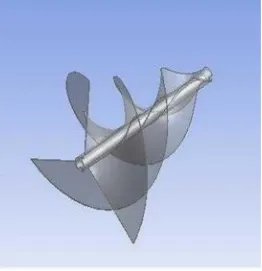
[image:2.612.185.447.130.401.2]The design of the Archimedes wind turbine is done by CREO parametric in such a way that spiral shape has to be formed this is initially done by producing two motions about a point such that a uniform motion in a fixed direction and a motion in a circle with constant speed. Fig 1 representing Archimedean spiral wind turbine of diameter 0.25 m and length 0.27 m length
Fig 1 Archimedes spiral rotor blade
The material used for the turbine blade is ABS (Acrylonitrile Butadiene Styrene) which has high heat resistance, toughness and internal resistance. The shaft is assembled to the turbine blade in which its inner hole radius is 16 mm. The fabricated equipment is attached to the frame, base.
III. SIMULATION ANALYSIS AND EXPERIMENTAL ANALYSIS
A. Simulation Method
The analytical method is used here is CFD based ANSYS CFX and version is ANSYS Workbench 16.2. Usually this type of software is based on CFD and major application is solve problems that are encountered such as heat transfer, mass transfer and chemical reactions. The Reynolds Averaged Navier Stokes Equation (RANS) and finite volume method is based on CFX. Also CFX consists of various turbulence models such that SST k-ω and k-ε model which is a mere benefit for it such the two models such as k
-ω represents k-turbulence kinetic energy and ω is the specific rate of dissipation and in k-ε represents such that k-turbulence kinetic
energy and ε is the rate of dissipation of turbulent kinetic energy [1].
B. Mesh Generation
59
[image:3.612.152.469.90.324.2]©IJRASET: All Rights are Reserved
Figure 2 Meshing of Stationary and Rotating domain 3.1.2 Boundary Setup
In ANSYS CFX analysis various conditions have been taken to predict power from the torque under different load conditions such as 50 grams, 100 grams, 150 grams and 200 grams. Various wind speed (m/s) and Turbine rotation (RPM) has been taken.
Figure 3 Boundary conditions setup at ANSYS CFX
Free slip boundary wall conditions have been applied at the top, bottom and side surfaces this means that there is no wind speed gradient normally and no flow across top, bottom and side surfaces.
C. Experimental Setup
[image:3.612.109.524.384.581.2]60
©IJRASET: All Rights are Reserved
[image:4.612.122.467.183.436.2]2) Experimental Setup: The experiment is conducted on centrifugal blower test rig which has motor speed of 2880 RPM and motor capacity of 5 HP. The blower is made to run at various speeds such that at the outlet air at different speeds is obtained by regulating the blower valve. Initially, experiment is carried out at no load and various load conditions such that different weights which are tied to the rope that surrounds the pulley that is connected to the aluminium shaft. The weights starting from the 50 grams, 100 grams, 150 grams and 200 grams are tied to the rope which surrounds the disc of 0.47 m diameter which is made up of Acrylic glass such that it minimises losses due to inertia about rotor axis. The rope is tied to the rope brake dynamometer which shows deflection of spring are Starting from no load the wind velocity occurred at the outlet is measured by anemometer and turbine speed is measured by digital tachometer.
[image:4.612.150.453.450.706.2]Figure 4 Experimental set up of wind turbine model assembly
61
©IJRASET: All Rights are Reserved
IV. RESULTS
A. Results from CFD analysis
The results of CFD analysis indicate aerodynamic characteristics of turbine blade. The inlet wind speeds with different turbine speed of wide range on different load conditions have been accounted. Table 1 represents results of power from both CFD and experiment is indicated which are obtained at different inlet wind speeds and turbine rotational speed under different load conditions. Experimental and simulation results of power show an increasing tendency with increase in wind speed under different load conditions.
[image:5.612.66.515.208.711.2]1) At Load of 50 Grams
Table 1: Comparison of Power produced by the turbine at different loads
S. NO
Wind Speed Speed of the turbine Power (Watts)
% Error
(m/sec)
Rpm Simulation Experimental
1 8.5 275.5 3.63 3.38 -7.39
2 10.8 487.9 10.33 12.01 13.91
3 13 680.7 20.82 25.13 17.14
4 15 989.7 40.23 42.62 5.61
At load of 100 grams
S. NO
Wind Speed Speed of the turbine Power (Watts)
% Error (m/s) Rpm
Simulation Experimental
1 16.7 234.7 12 12.71 5.88
2 18.2 465.3 28.03 29.77 5.84
3 20.5 773.2 59.74 60.88 1.87
4 23 1204 117.23 118.51 1.08
b) At load of 150 grams
S.NO
Wind Speed Speed of the turbine Power (Watts)
% Error
(m/s)
Rpm Simulation Experimental
1 21.1 295 24.09 25.4 5.15
2 24.2 587 62.4 60.06 -3.86
3 25.4 758 88.78 89.53 0.83
4 27.3 1188 160.7 160.7 0
c) At load of 200 grams
S.NO
Wind Speed Speed of the turbine Power (Watts)
% Error
(m/s)
Rpm Simulation Experimental
1 28.3 906 131.906 133.775 0.01
62
©IJRASET: All Rights are Reserved
B. Comparison of Experimental and CFD Analysis
[image:6.612.177.421.133.327.2]The result of power comparison between both simulation and experimental conditions as shown in the figure 5 such that both the power obtained from experimental and simulation agrees and both shows an increasing tendency. So, the results calculated from CFD analysis are power, velocity contour, pressure and streamlines.
Figure 6 Streamlines
The figure 6 shows velocity streamlines in which the influence of wind speed velocity over the turbine to determine its uniform passage and swivels at some portion to be determined. For every increase in wind speed the increase in velocity occurred at the portion which are indicated in the red lines at some portion of the turbine.
The pressure contours at various inlet wind speeds at different load At 50 grams load
(a) 8.5 m/s (b) 10.8 m/s
63
©IJRASET: All Rights are Reserved
1) At 100 Grams Load
(a) 16.7 m/s (b) 18.2 m/s
(c) 20.5 m/s (d) 23 m/s
2) At 150 Grams Load
(a) 21.1 m/s (b) 24.3 m/s
64
©IJRASET: All Rights are Reserved
3) At 200 Grams
(a) 28.3 m/s (b) 29.5 m/s
It is observed from all pressure contours that red colour presence on the surface of the turbine which indicates that pressure is increased at the surface of the turbine which is related to the structure and efficiency of the turbine such that the increase in pressure leads to damage of turbine in future which also depend upon material used ABS (Acrylonitrile Butadiene Styrene) and also it is observed that the pressure contour increases with increase in wind speed at particular load.
The velocity contours at various speeds under different load conditions At 50 grams load
(a) 8.5 m/s (b) 10.8 m/s
(c) 13 m/s (d) 15 m/s
4) At 100 Grams Load
65
©IJRASET: All Rights are Reserved
(c) 20.5 m/s (d) 23 m/s
5) At 150 Grams
(a) 21.1 m/s (b) 24.3 m/s
66
©IJRASET: All Rights are Reserved
6) At 200 Grams Load
(a) 28.3 m/s (b) 29.5 m/s
The velocity contour indicates that the velocity at the centre of mass of the blade is more for a wind speed. So, as the wind speed increases the velocity or turbulence at the centre of turbine blade is also increased which is indicated in the red colour. The velocity contour concluded that velocity has not much influence in structural damage to the turbine.
V. CONCLUSIONS
The Archimedes spiral wind turbine of 0.25 m diameter and 0.27 m length is designed to predict aerodynamic characteristics such as power, torque, velocity distribution and pressure distribution. Initially the wind turbine is designed in CREO 2.0 parametric and analysed in CFD simulation like ANSYS CFX for determining power, velocity distribution, and pressure distribution and compared with the results obtained through field test in which both tests agree with each other. The following conclusions are drawn which are summarised as
A. This work provides that the ANSYS CFX is efficient software for producing power which undergoes high methods of resolution in determining fluid flow, power at different wind speed, pressure coefficient and velocity coefficient.
B. It produces maximum power of 118.51 watts under low speed and design configuration of the blade.
C. The material Acrylonitrile Butadiene Styrene (ABS ) used as turbine blade material is best suited due to its impact resistance, strength and heat resistance.
D. As there is a use of tangential, radial and axial forces so it is unnecessary to use electric yawing equipment.
E. As per the CFD ANSYS CFX results this Archimedes wind turbine is better than HAWT in terms of promising power and due to the design parameters of the blade we can extract power under low speed.
F. ANSYS CFX agrees with experimental observations which are taken by the running centrifugal blower test rig.
G. The pressure contours indicate that highest pressure of magnitude is 1489.54 Pa is found on the surface of the blade tip and low pressures is found at the back thus resulting in lifespan of the wind turbine blade.
H. The velocity contour indicate that highest velocity is obtained as 76.26 ms-1 so there is low velocity distribution throughout the turbine blade and its life workability is safe under various conditions.
REFERENCES
[1] Dr S. Srinivasa Rao and Kota Shanmukesh et al “Design and analysis of Archimedes aerofoil wind turbine through low and moderate wind speed” IJRMEE, August 2018, Volume:5, Issue:8,Pg No: 01-05, www.ijrmee.org
[2] Dr.S.Srinivasa Rao, B Rakesh, Ch.Y.V. Kiran Kumar, M.Anand Kumar, D.Duryodhana “Design fabrication and experimental analysis of Archimedes Spiral Wind Turbine” April 2019, IJIRT 147913, Volume 5, Issue 11, Pg No: 304-310
[3] Sashank Chaudhary, Shubham Jaiswal, Richa Nanda, Saurabh Patel“Comparison of torque characteristics of Archimedes wind turbine blade evaluated by analytical and numerical study” Aug-2016, IJMPE, Vol-5, Issue-8, Pg no:75-78
[4] Peter j. Schubel and Richard J Crossley, “Wind Turbine Blade design” Energies 2012, 5, 3425-3449; doi: 10.3390/en5093425.
[5] Shafiqur Rehman, Md.Mahbub Alam, Luai M. Alhems, “ Horizontal axis wind turbine blade design methodologies for efficiency enhancement” Energies 2018, 11,506; doi:10.3390/en11030506.
[6] Mahmood M. Shokrieh, Roham Rafiee, “Simulation of fatigue failure in a full composite wind turbine blade” 13 June 2005, Composite structures 74 (2006), 332-342, doi:10.1016/j.compstruct.2005.04.02
[7] Ismail B.Celik, “Introductory turbulence modelling” Dec-1999,
[8] Ho Seong Ji, Joon Ho BAEK, “The aerodynamic performance study on small wind turbine with 500W class through wind tunnel experiments” IJRES, 2016, Vol-1, www.iaras.org, Page no: 7-12.
67
©IJRASET: All Rights are Reserved
[10] Bhushan.S.Patil “Computational fluid dynamic analysis of wind turbine at various angles of attack and different Reynolds number” Procedia Engineering 127(2015), 1363-1369, ICCHMT, doi:10.1016/j.proeng.2015.11.495.
[11] Kyung Chung Kim, Ho Seong Ji, “Experimental and numerical study of aerodynamic characteristics of Archimedes wind turbine blade” Energies 2014, 7, 7893-7914; doi: 10.3390/en7127893.
[12] Raju kumar, Priyanka Jhawar, “A CFD analysis of a wind turbine blade design at various angles of attack and low Reynolds number” IJSRET, Vol-2, Issue-5, Sept 2016, ISSN (Online):2395-566X, Pg No:1-7.
[13] Han Cao, “Aerodynamic analysis of a small horizontal axis wind turbine blades using 2D and 3D CFD modelling”, May 2011, Pg No: 1-93.
[14] Arman Safdari and Kyung Chun Kim, “Aerodynamic and structural evaluation of Horizontal Archimedes of wind turbine” Journal of clean energy technologies, Vol-3, No-1, January 2015, Pg No:1-5.
[15] Yoon keen Kim and Qian Lu “A multi-prong study on aerodynamic characteristics of Archimedes spiral wind turbine blade” Pg no:1-6. [16] Asress Mulugeta Biadgo and Gerawork. “Aerodynamic design of Horizontal axis wind turbine blades” FME transactions (2017) 45, 647-640.
[17] Wirron monatrakul and Ratchaphon. “Effect of blade angle on turbine efficiency of spiral horizontal axis turbine” Sciencedirect Energy procedia 138 (2017) 811-816.
[18] Hiroyunki hirahara and M. Zakir Hussain.”Testing basic performance of a very small wind turbine designed for multi purposes” Renewable Energy 38 (2005) 1279-1297.
[19] Nobyunki fujisawa. “Velocity measurements and numerical calculations of flow fields in and around Savonius rotors” Journal of wind engineering and industrial aerodynamics 59 (1996) 39-50.
[20] Nak joon choi, sang hyun nam, Jong hyun jeong, hyung chin kim. “Numerical study on the Horizontal axis wind turbines arrangement in a wind farm: Effect of separation distance on the turbine aerodynamic output” J.Wind Eng.Ind, Aerodyn. 117 (2013)
[21] Chein-chang chen and Cheng hsiung Kuo. “Effects of pitch angle and camber angle on flow characteristics and performance of a small size Darrieus VAWT” J Vis (2013) 16:65-74.
[22] Marco Bortolini, Mauro Gamberi, Alessandro Graziani. “Performance and viability analysis of small wind turbine in european union” Renewable energy 62 (2014) 629-639.