Optimisation of Process Parameter for Material
Removal Rate of Wire Cut EDM using Taguchi
Method
Shrey Kapoor1, Mr. Sharad Shrivastava2 1
M.Tech, Department of Production engineering, Rajasthan Institute of Engineering and Technology, Jaipur
2
Assistant Professor, Department of Mechanical Engineering, Rajasthan Institute of Engineering and Technology, Jaipur
Abstract: Accompanying the development of production, aerospace and automotive industries, the demand for alloy materials
having high hardness, toughness and impact strength are increasing. As these alloy materials are having high material properties for machining them to finish product, need high advantageous machines other than traditional machines. So to machine these materials non-traditional machine are used which are very advantageous. Wire Cut EDM (WEDM) machine is non-traditional machine which have application to cut electrical conduction material irrespective of their high physical and chemical properties.
The ultimate requirement in manufacturing is to have high material removal rate (MRR). The paper deals with the optimisation of process parameters of WEDM to machine M-35 HSS with 5% Cobalt material. The process parameter pulse on time (ton), pulse off time (toff) and wire feed (Wf) are optimised using Taguchi’s method. The result shows optimised values of parameters for material to get high MRR.
Keywords: Wire Cut EDM (WEDM), material removal rate (MRR), M-35 HSS with 5% Cobalt material, Taguchi’s method
I. INTRODUCTION
Electrical discharge machining (EDM) is a non-traditional, thermo electrical process, which erodes material from the work piece by a series of discrete sparks between the work and tool electrode immersed in a liquid dielectric medium. These electrical discharges melt and vaporize minute amounts of the work material, which are then ejected and flushed away by the dielectric.
A wire EDM generates spark discharges between a small wire electrode and a work piece with de-ionized water as the dielectric medium and erodes and work piece to produce complex two and three-dimensional shapes according to a numerically controlled (NC) path.
The main goals of WEDM manufacturers and users are to achieve a better stability and higher productivity of the WEDM process. As newer and more exotic materials are developed, and more complex shapes are presented, traditional machines continue to reach their limitation and to machine alloy material having WEDM machine plays a key role and its usage in manufacturing field accelerating.
Wire electrical discharge machining manufactures and users emphasize on achievement of higher machining productivity with a desired accuracy and precession. To machine tough physical property materials with optimal values we need to find better values of input parameters to achieve desire output.
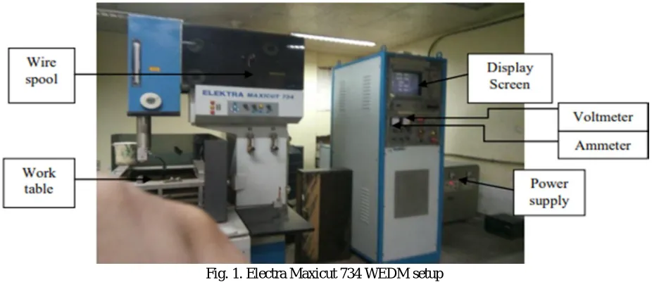
II. EXPERIMENTAL SETUP
In wire electrical discharge machining (WEDM), a thin single-strand metal wire, usually brass, is fed through the work piece, submerged in a tank of dielectric fluid, typically deionised water. Wire-cut EDM is typically used to cut plates as thick as 300mm and to make punches, tools, and dies from hard metals that are difficult to machine with other methods.
Fig. 1. Electra Maxicut 734 WEDM setup
III. WORKPIECE MATERIAL
M-35 HSS with 5% Cobalt material is used as work material. It is having several advantages in making parting blades, tool bits etc.
Table I
[image:2.612.100.511.353.543.2]Chemical Composition Of Work Piece
Fig. 2. M-35 HSS with 5% Cobalt
IV. METHODOLOGY
[image:2.612.151.467.650.739.2]Process parameters are pulse on time, pulse off time and wire feed are taken in three levels and experimented as per the L9 orthogonal array which is created by MINITAB software. There are nine experimental inputs which are varied for each cut and other parameters are set constant. For each cut the material removed is calculated and Taguchi optimisation technique is applied to find optimised value for higher MRR.
Table II
Process Parameter And Their Levels
Parameter Symbol Unit Level
Table III. Taguchi Orthogonal Array L9 Ton
(µs)
Toff (µs)
Wf (m/min)
4 3 3
4 4 4
4 5 5
5 3 4
5 4 5
5 5 3
6 3 5
6 4 3
6 5 4
V. RESULT & DISCUSSION
A. Experiment for MRR
The process parameter varied for nine different set of values which gives respond parameter as MRR which show in following table. TABLE IV. RESULT TABLE FOR MRR
Ton (µs)
Toff (µs)
Wf (m/min)
MRR (mm3/min)
4 3 3 0.321
4 4 4 0.381
4 5 5 0.45
5 3 4 0.495
5 4 5 0.356
5 5 3 0.451
6 3 5 0.479
6 4 3 0.501
6 5 4 0.382
B. Analysis
Output values of MRR for selected process parameter is now analysed using Taguchi Method in Minitab software and signal to noise ratio and mean values are calculated. Signal to noise ratio calculated to eliminate loss factors.
TABLE V. Values Of S/N Ratio And Mean For Mrr
Ton Toff Wf MRR
MRR* S/N ratio MEAN
4 3 3 0.321 -9.8699 0.321 4 4 4 0.381 -8.3815 0.381 4 5 5 0.45 -6.93575 0.45 5 3 4 0.495 -6.1079 0.495 5 4 5 0.356 -8.971 0.356
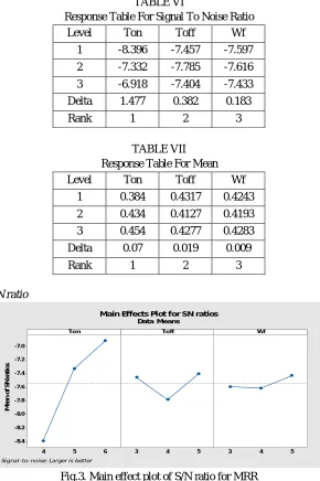
C. Response Table
After getting values of S/N ratio and mean the optimised response table is outputted as per Taguchi method, which gives delta values of each parameter and rank as per their influencing the response parameter.
TABLE VI
Response Table For Signal To Noise Ratio Level Ton Toff Wf
1 -8.396 -7.457 -7.597
2 -7.332 -7.785 -7.616 3 -6.918 -7.404 -7.433 Delta 1.477 0.382 0.183
Rank 1 2 3
TABLE VII Response Table For Mean Level Ton Toff Wf
1 0.384 0.4317 0.4243 2 0.434 0.4127 0.4193
3 0.454 0.4277 0.4283 Delta 0.07 0.019 0.009
Rank 1 2 3
[image:4.612.162.452.134.570.2]D. Graphs for mean and S/N ratio
[image:4.612.158.458.592.719.2]Fig.3. Main effect plot of S/N ratio for MRR
Fig.4. Main effect plot of mean For MRR 6 5 4 -7.0 -7.2 -7.4 -7.6 -7.8 -8.0 -8.2 -8.4 5 4
3 3 4 5
Ton M e a n o f S N r a ti o s Toff Wf
Main Effects Plot for SN ratios
Data Means
Signal-to-noise: Larger is better
6 5 4 0.46 0.45 0.44 0.43 0.42 0.41 0.40 0.39 0.38 5 4
3 3 4 5
Ton M e a n o f M e a n s Toff Wf
Main Effects Plot for Means
E. Result
From the graphs of S/N ratio and mean we can come to a result that for machining M-35 HSS with 5% Cobalt material to get high MRR respond factor we need to set process parameter as given in following table.
TABLE VIII
optimal Parameter for High MRR Pulse on time 6µs Pulse off time 3µs
Wire feed 5m/min
VI. CONCLUSION
On the basis of experimental result, from S/N ratio, mean values and graph plots for both, we can come to a conclusion that to machine M-35 HSS with 5% cobalt material to get higher MRR respond factor the values for process parameters pulse on time is 6µs, pulse off time is 3µs and wire feed is 5m/min. Also we have ranks for factors with influences the respond factor MRR as per their ranks so in the response table we have pulse on time as rank 1, it means pulse on time highly influence MRR then we have pulse on time as rank 2 which shows it has intermediate impact on response factor and wire feed has rank 3 which denotes it has less influence on MRR.
REFERENCES
[1] Prasath. K, R.Prasanna, Milon D.Selvam, Optiisation of process parameters in wire cut EDM of mild steel and stainless steel using robust design, International Journal of ChemTech Research, 2018,11(01): 83-91. 85
[2] S. Dhamotharan, B. Babu, Optimisation of Machining Parameters in Wire Cut EDM for Cemented Tungsten Carbide using Taguchi Technique, International Journal for Research in Applied Science & Engineering Technology, ISSN: 2321-9653, Volume 6 Issue XI, Nov 2018.
[3] Kadirgama, K., Noor, M.M. and Rahman, M.M., Optimization of surface roughness in end milling on mould aluminium alloys (AA6061-T6) using response surface method and radian basis function network. Jourdan Journal of Mechanical and Industrial Engineering, 2(4), 2008.
[4] Lin, J.L. and Lin, C.L., The use of the orthogonal array with grey relational analysis to optimize the electrical discharge machining process with multiple performance characteristics. International Journal of Machine Tools and Manufacture, 42(2), pp.237-244, 2002.
[5] Selvam, M.D., Dawood, D.A.S. and Karuppusami, D.G., Optimization of machining parameters for face milling operation in a vertical CNC milling machine using genetic algorithm. IRACST Engineering Science and Technology: An International Journal (ESTIJ), 2(4), 2012.