Mechanical Properties of Thermomechanical Treated Hyper-Eutectic
Al–Si–(Fe,Mn,Cu) Materials
Osamu Umezawa
*Division of Mechanical Engineering and Materials Science Graduate School of Engineering, Yokohama National University, Yokohama 240-8501, Japan
Tensile and high-cycle fatigue behavior of thermomechanical treated hyper-eutectic Al–Si–(Fe,Mn,Cu) materials were studied. Through the repeated thermomechanical treatment (RTMT) which is a repeat of the multi steps cold-working followed by heat treatment, Si crystals and/ or intermetallic compounds were broken into some fragments and dispersed in the aluminum matrix. Fine dispersion of the second phase particles exhibited good ductility, since early fracture was overcome. A few large Si crystals or aggregates of compounds, however, gave an origin of fatigue crack generation. Since microcrack linkage generates a larger fetal crack, not only refinement but also random distribution of second particles may be required to improve fatigue strength at and below room temperature. At higher temperature, on the other hand, dynamic recovery may cause apparent strain rate dependence on flow curves.
(Received July 4, 2005; Accepted August 26, 2005; Published December 15, 2005)
Keywords: aluminum–silicon alloys, thermomechanical treatment, microstructual refinement, flow stress, ductility, fatigue fracture
1. Introduction
Al–Si alloys are one of major cast materials, and have much advantage of the recyclable material design as
mentioned in the reference.1) However, coarse Si crystals
and/or intermetallic compounds cause poor ductility and often give an origin of fatigue crack initiation site as well as inclusion. The ductility must be improved to apply Al–Si alloys to wrought products such as forged parts and extruded ones. To improve both workability and mechanical proper-ties, it is necessary that the Si crystals and compounds are refined to avoid the sample fracture due to their cracking. Microstructural modifications have been commonly achieved by the addition of elements such as Sr and P into the melt, or by the hot-forging and long-time solution heat-treatment. Nevertheless, the ductility of the treated materials is not enough, and they can hardly be applied to wrought materials. The most promising method of refining microstructures is rapid solidification. Spray-forming and thixoforming have
been used for refining the Si in Al–Si alloys.2,3) The rapid
solidification methods, however, are not amenable to mass production. That is why the present work deals with a novel thermomechanical treatment for hyper-eutectic Al–Si based
cast alloys. Umezawa and Nagai4)have proposed a repeated
thermomechanical treatment (RTMT) to produce a heavily deformable hyper-eutectic Al–Si material. Furthermore, not only silicon but also iron, manganese and copper are major impurities in the secondary aluminum cast alloys, and those elements form intermetallic compounds. The RTMT has
successfully provided a fine dispersion of the compounds.5–7)
Basic ideas for the design and control of themesocomplex
structure,1)where the second phase basically are distributed
in matrix with high density and fine structure, are mentioned in the followings (Fig. 1). In those the heavy working plays an important role on building the fine microstructure.
(1) Microscopic distribution of second phase:
When second phase is deformable, the increase of
plastic strain leads to the decrease of lamella spacing. When second phase cannot be deformed, the plastic strain causes the cracking of second phase.
(2) Role of second phase as a pinning site for deformation of matrix:
The rapid increase of plastic strain in the matrix makes a dynamic recovery and recrystallization in fine scale grain size. The second phase is a site for local deformation and a pinning site for the dynamic recovery in matrix.
When the second phase particles, i.e. Si crystal and
intermetallic compound, in the soft matrix (Al) is non-deforming, the plastic work causes a cracking into the second phase. The succeeding heat treatment softens the aluminum matrix again. Since the liner thermal expansion coefficient of aluminum is much higher than that of Si, especially at higher temperature, voids or microcracks may partially heal during heat treatment. Successive cold working pressed the cracks and separated the segments with the flow of aluminum. Therefore, the repeat of cold work and annealing operations is believed to result in the annihilation of the cracks. Consequently, several times combination of the thermome-chanical treatment can make the fine dispersion of Si and compound phases. In addition, the speroidization of them is attained within several hours, although nearly ten hours are needed to speroidize large Si crystal for the Al–Si cast materials. Such modification of microstructure reveals
sig-nificantly increase of ductility.4,5,8)The RTMT is beneficial
for not only cracking Si and compounds, but also healing cracks and speroidizing them.
Microcrack linkage model, however, has pointed out concerning effects of brittle phases on the mechanical
properties.9)Coarse Si crystal gives a fatigue crack initiation
site.10) The manor is remarkable in the low temperature
regime, since slip deformation modes are rather limited.11)
In the present study, therefore, the flow stress and high-cycle fatigue behavior for the thermomechanical treated hyper-eutectic Al–Si based alloys were examined.
*Corresponding author, E-mail: [email protected]
Materials Transactions, Vol. 46, No. 12 (2005) pp. 2616 to 2623 Special Issue on Growth of Ecomaterials as a Key to Eco-Society II
2. Experimental Procedure
2.1 Materials
The test materials are five kinds of hyper-eutectic Al–Si– (Fe,Cu,Mn) alloys. Their chemical compositions are listed in Table 1. In L1 to L4, rods with 39 mm in diameter were machined from alloy ingots produced by a permanent mold
casting.6,7)In the case of ingots cooled slowly, cast materials
exhibit extremely low workability at and below room temperature, since they involve very large Si crystals and compounds. They need to introduce a hot-working step providing a certain cold-workability such as 20% reduction
without visible cracks.12)The cast rods, L1 to L4, were heated
at temperature between 673 and 693 K, and were either extruded (L1, L2 and L3) or swaged (L4) with working strain
of 0.97 (¼lnA0=A,A0: section area of sample, A: section
area of worked sample). Both the hot-extruded rods (HE) and the hot-swaged ones with 21 mm in diameter were annealed at 793 K for 3.6 ks, and then the repeated thermomechanical
treatment (RTMT)4) was conducted. For the RTMT,
cold-working operations were carried out in several steps; intermediate annealing operations at 793 K for 3.6 ks were introduced to soften the worked materials. The cold-working operation by swaging was done out in a number of multiple passes or steps at room temperature. Each cold
reduction was less than 20% in section area, and the cold-work-anneal cycle was repeated over four times. The total reduction in area was about 70%.
On the other hand, SF material was produced by spray
forming (Ospray method) and hot-extruded at 673 K by
67.4 percent reduction in area.2,3)
2.2 Tensile test
Tensile specimens were machined from the rods parallel to the longitudinal direction. Tensile testing was conducted in a motor-driven testing machine at 77 K (immersed in liquid nitrogen), 293 K (in air) and 453 K (immersed in oil) under displacement control. Displacement rate for each specimen was chosen to correspond to an engineering strain rate of
approximately from3:3104 to 3.3 per second within the
plastic regime. Specimen elongation was monitored by a clip gauge with knife edges set onto the tensile specimen at both ends of the gauge length. Engineering stress and strain data were converted to true stress and true strain values by assuming volume conservation during uniform elongation.
2.3 Hardness test
[image:2.595.111.483.72.314.2]Micro-vickers hardness tests for the L4 and SF materials were done. In the low temperature regime, the samples were kept in a bath with temperatures at 77, 213 and 293 K. High Fig. 1 Effects of coarse second phase on microstructure evolution through severe deformation process.
Table 1 The chemical compositions of the test materials.
Material Concentration/mass%
Si Fe Cu Mg Mn Cr Zn Ti
L1 12.5 2.14 0:004 0:010 <0:001 <0:001 0.004 0.011
L2 12.0 0.11 3:43 0:009 <0:001 <0:001 0.003 0.010
L3 20.6 0.13 0:027 0:008 0:006 0:006 0.005 0.005
L4 7.56 2.56 <0:01 <0:01 1:83 — — —
[image:2.595.44.550.370.460.2]temperature micro-vickers hardness tests by using type-QM2, Nikon, were also carried out at 323, 373, 423, 473, 523, 573, 623 and 673 K during heating for a sample.
2.4 Fatigue test
Using a servo hydraulic fatigue test machine, load-controlling tests were carried out with stress ratio,
Rðmin=maxÞ ¼0:01, in a sine wave at 296 and 77 K.
Hourglass shaped fatigue test specimens were machined with minimum diameter of 3 mm from the rods parallel to the longitudinal direction.
2.5 Microstructural analyses
SEM (scanning electron microscopy)-EDS (energy dis-persive spectroscopy) analyses for both microstructure and fracture surface were carried out. Orientation imaging microscopy which is based on electron backscatter diffrac-tion (EBSD) in SEM was applied to determine the grain boundary characteristics in the microstructure. X-ray dif-fraction (XRD) analysis was also done to characterize second phase.
3. Results and Discussion
3.1 Microstructure and plasticity
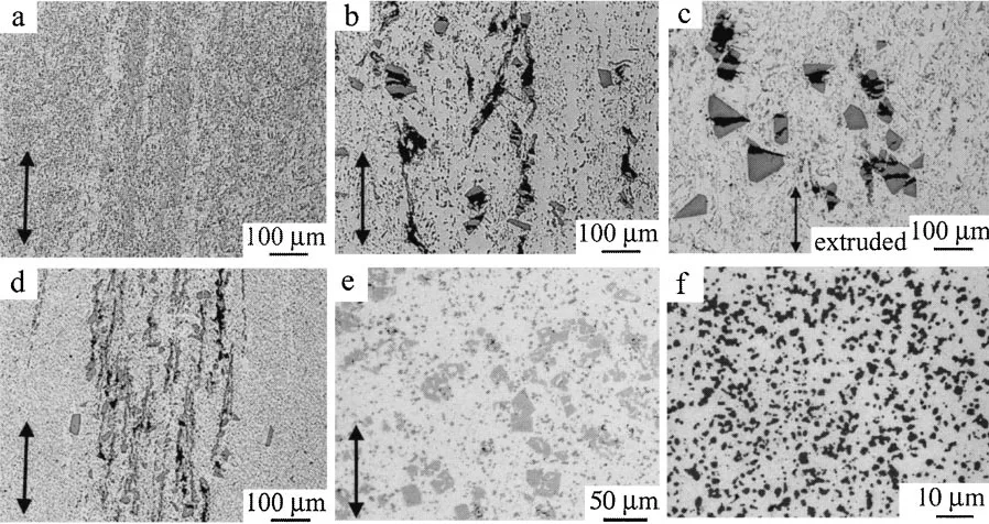
Figure 2 shows microstructure of the test materials in the center part of longitudinal section. In the L1 RTMT, acicular
intermetallic compound,phase (Al5SiFe), are divided into
the pieces of less than a few tenmmin length [Fig. 2(a)]. In
the L2 RTMT, primary Si crystals are refined to less than
50mmin diameter [Fig. 2(b)], although their fragmentation
and dispersion in the aluminum matrix are not enough. For the L3 HE as extruded rod, primary Si crystals were cracked as shown in Fig. 2(c). In the L3 RTMT, primary Si crystals
are refined to less than 20mmin diameter, but the cracks in
the primary Si remain [Fig. 2(d)]. In the L4 RTMT, the size
[image:3.595.73.522.519.757.2]of primary compounds is less than a few tenmmin diameter
[Fig. 2(e)]. Mostly Si crystals and compounds are aligned along the longitudinal direction (RD). Eutectic Si crystals are commonly broken and dispersed as spheroidized particles. In the SF, Si crystals are uniformly dispersed with high density
in the aluminum matrix and their size is about 2mm in
diameter [Fig. 2(f)].
For the resulting RTMT materials in the final annealed state, multiple-pass swaging was successfully done over 90%
reduction in section area.6,7) In the matrix of the severely
deformed materials, the highly dense dislocation structure were not observed, but the sub-grains structure with about
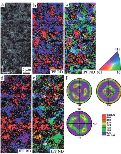
200 nm in diameter was detected.6) Figure 3 shows EBSD
analysis images in the transverse (RD) section of the worked
rod. In the case of rod, {111} fiber and {100} cube texture
appear in the plane normal to the RD [Fig. 3(f)]. Even as cold-worked condition, the average grain size with high angle
grain boundaries is above 1mm, according to the comparison
with the orientation maps along RD [Fig. 3(b)] and ND [Fig. 3(c)]. Dynamic recovery and/or continuous
recrystal-lization may occur around second particles predominantly.13)
Furthermore, grain refinement occurred at a dramatically higher rate in the particle-containing alloy during severe
deformation processing.14)After aging, {111} fiber grains
were rotated along RD and became larger with several mm
[Figs. 3(d) and (e)], but no big difference in texture and microstructure was appeared. If the finished product must be stronger than the fully annealed material, then the final operation must be a cold-working step with the proper degree of deformation to produce the desired strength. Such a procedure to develop a certain combination of strength and ductility in the final product is more successful than trying to achieve the same combinations of properties by partially softening a fully cold-worked material.
Fig. 2 Microstructures of the test materials in the longitudinal section: (a) L1 RTMT, (b) L2 RTMT, (c) L3 HE (d) L3 RTMT, (e) L4 RTMT and (f) SF.
3.2 Tensile properties
Figure 4 summarized tensile strength and elongation for the test materials. All cast materials showed poor elongation and early fracture caused by second phase cracking. At both 77 and 296 K, the RTMT materials had a significantly enhanced ductility as well as SF. The RTMT samples showed the necking instability. Especially at lower temperature, microstructural refinement could result in the avoidance of early fracture. On the other hand, ultimate tensile strength of the RTMT materials was higher that of the cast ones, but no
big difference was between them. 0.2% proof stress of the RTMT materials was much lower than that of cast ones. The fracture surface showed a ductile fracture manner, but numerous cracked particles were observed as shown in Fig. 5. Cracking of big particles either Si or compound and their linkage with plastic shearing may have an important
role in the damaged process.15)Microstructural modifications
by both spray forming and RTMT are effective to improve tensile properties.
[image:4.595.83.507.64.606.2]3.3 Strain rate dependence and dynamic recovery Although almost no strain rate dependence on flow carves was detected at 293 K, it markedly revealed at 453 K as shown in Fig. 6. At 77 K, on the other hand, strain rate dependence on flow carves was also revealed. It shows that the thermally activated process on dislocation gliding appears below 293 K. Dynamic recovery, therefore, may cause the strain rate dependence at higher temperature. Influence of temperature on thermal activated process was analyzed by hardness. Figure 7 shows the relationship between hardness and 1/T. Two tangent lines from both low and high temperatures are installed in the figure. Those are crossed at around 460 K. This transformation may correspond to a change of deformation mode that is between
low temperature deformation type of thermal activated process and high temperature one with dynamic recovery. But it occurs continuously and the recovery process may be active above 293 K. It is substantiated the sub-grains structure formation mentioned in above.
3.4 Fatigue strength and crack generation
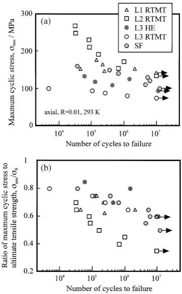
Figure 8(a) shows S–N data at 293 K. The SF shows higher fatigue strength in high-cycle range than L3 HE and RTMT.
In SF material,107cycles fatigue strength is about 90 MPa at
293 K. At 77 K, fatigue strength in high-cycle range was 100 MPa. The increase of fatigue strength with lowing temperature was proportional to the increase in tensile strength. In both L3 HE and L3 RTMT, on the other hand, there is no big difference of fatigue strength between in low
cycle and high cycle. Ratio of107cycles fatigue strength to
ultimate tensile strength is about 0.5 at 77 and 293 K. At 77 K, the fatigue strength is 40 MPa higher than that at 296 K, although tensile strength increase is 80 MPa. In the L3 HE,
107 cycles fatigue strength is about 60 MPa at 293 K and
Fig. 5 Tensile fracture surface of L4 RTMT at 293 K. Photograph (b) is a magnified image in photograph (a).
Fig. 4 Tensile strength and elongation of the test materials with initial strain rate of3:3103s1.
[image:5.595.57.291.67.567.2] [image:5.595.307.547.69.486.2]85 MPa at 77 K. The fatigue strength becomes 25 MPa higher, although tensile strength is 44 MPa higher. In those materials including coarse primary Si crystal, the difference in fatigue strength between 77 and 296 K does not correspond to that in tensile strength.
L1 and L2 showed almost the same 107 cycles fatigue
strength at each temperature, although tensile strength of L2
was higher than that of L1. Ratio of 107 cycles fatigue
strength to ultimate tensile strength for L2 was about0:35B
at 296 K and0:45Bat 77 K. L1 exhibits a good ratio of107
cycles fatigue strength to ultimate tensile strength. Lower the temperature is, better the balance between tensile and fatigue properties exhibits.
In SF material, fatigue crack initiated near specimen surface. In some cases pore and inclusion were detected at the origin as shown in Fig. 9(d), but no Si cracking was observed. On the contrary, coarse primary Si crystal was selected as a major origin of fatigue crack initiation site in L3 HE and L3 RTMT as shown in Figs. 9(a) and (b). Primary Si crystals in RTMT material were almost broken during RTMT process, but a few of larger Si crystals remained. It is considered that cracking of the remained large Si crystals gave an origin of fatigue crack initiation. A few of larger Si crystals in the L2 were also remained and gave an origin of fatigue crack initiation. The influence of Si crystal size on
fatigue life is applicable as mentioned in the reference.10)
Fig. 6 Strain rate dependence on true stress-true plastic strain curve of L4
RTMT at 293 K (a) and 453 K (b). Fig. 7 Relationship between hardness and 1/T for L4 RTMT (a) and SF (b).
[image:6.595.79.273.64.426.2] [image:6.595.330.525.71.432.2] [image:6.595.336.517.476.768.2]Fig. 9 Matching halves of near fatigue crack initiation site of the L3 RTMT sample fractured at 77 K (max¼133MPa, Nf¼1604240
cycles). Photograph (c) shows fatigue fracture surface of the SF sample fractured at 293 K (max¼222MPa, Nf¼1638800cycles).
[image:7.595.82.515.71.373.2]Photograph (d) is magnified image near fatigue crack initiation site of photograph (c).
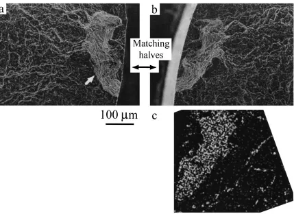
Fig. 10 Matching halves of near fatigue crack initiation site of the L1 RTMT sample fractured at 77 K (max¼249MPa, Nf¼1535800
cycles). An arrow indicates the crack initiation site. Micrograph (c) shows iron image of the region in (b).
[image:7.595.85.514.446.758.2]No only large Si crystals but also compounds were selected as a major origin of fatigue crack initiation site in RTMT materials. In L1, crack initiation site was identified as an aggregate of broken compounds as shown in Fig. 10. At the initiation site, iron is enriched [Fig. 10(c)]. The acicular compounds were fully fragmented, but were aligned. In this case, microcrack linkage may generate a larger fetal crack. In order to improve fatigue strength of RTMT material, there-fore, not only refinement but also random distribution of second particles may be required. Thus second phase compound is needed to control itself as not acicular but globular form in the cast structure.
4. Conclusions
We have studied the tensile and high-cycle fatigue behavior of thermomechanical treated hyper-eutectic Al– Si–(Fe,Mn,Cu) materials. During the RTMT process, Si crystals and/or intermetallic compounds were broken into some fragments and dispersed in the aluminum matrix. Main results are as follows;
(1) Fine dispersion of the second phase particles resulted in good ductility, since early fracture was overcome. (2) Above 450 K, dynamic recovery may cause apparent
strain rate dependence on flow curves.
(3) A few large Si crystals or aggregates of compounds gave an origin of fatigue crack generation. Since microcrack linkage generates a larger fetal crack, not only refinement but also random distribution of second particles may be required to improve fatigue strength at and below room temperature.
Acknowledgement
This work has been supported by Nissan Foundation and by RISTEX of Japan Science and Technology Agency. The author thanks Drs. H. Yokoyama (Nittan Valve) and Y. Osawa (NIMS) for their experimental help.
REFERENCES
1) O. Umezawa and K. Nagai: Trans. MRS-J20(1996) 190–193. 2) K. Shibue and N. Tokizane: Mater. Jpn. 34 (1995) 736–740 (in
Japanese).
3) N. Tokizane, H. Sano, K. Shibue and Y. Ohkubo: J. Jpn. Soc. Powder Powder Metall.41(1994) 927–932 (in Japanese).
4) O. Umezawa and K. Nagai: Metall. Mater. Trans. A30A(1999) 2221– 2228.
5) C.-Y. Lim, O. Umezawa and K. Nagai: Metals & Mater. Int.4(1998) 1027–1031.
6) O. Umezawa, H. Yokoyama and K. Nagai:Int. J. Mater. & Product Tech.,Special Issue,SPM1(2001) 568–573.
7) O. Umezawa, M. Nakamoto, Y. Osawa, K. Suzuki and S. Kumai: Mater. Trans.46(2005) 2609–2615.
8) G. Guiglionda and W. J. Poole: Mater. Sci. Eng. AA336(2002) 159– 169.
9) J. Gammage, D. Wilkinson, Y. Brechet and D. Embury: Acta Mater.52
(2004) 5255–5263.
10) Y. Murakami, K. Ohyama, H. Ikeda, T. Takahashi and H. Kobayashi: J. Soc. Mater. Sci. Jpn.44–497(1995) 194–200 (in Japanese). 11) O. Umezawa and K. Nagai: ISIJ International37(1997) 1170–1179. 12) H. Yokoyama, O. Umezawa, K. Nagai and K. Kokubo:Proc. 4th Inter.
Conf. ECOMATERIALS, (The Society of Non-traditional Tech., Tokyo, 1999) 491–494.
13) F. J. Humphreys: Acta Metall.45(1997) 1323–1344.
14) P. J. Apps, J. R. Bowen and P. B. Prangnell: Acta Mater.51(2003) 2811–2822.
15) A. Mocellin, Y. Brechet and R. Fougeres: Acta Metall. Mater. 43