Eye centre localisation and gaze gesture recognition
for human computer interaction
W
ENHAO
Z
HANG
,
*
M
ELVYN
L.
S
MITH
,
L
YNDON
N.
S
MITH
,
A
BDUL
F
AROOQ
Centre for Machine Vision, Bristol Robotics Laboratory, University of the West of England, T Block, Frenchay Campus, Coldharbour Lane, Bristol, BS16 1QY, UK
*Corresponding author: [email protected]
Received XX Month XXXX; revised XX Month, XXXX; accepted XX Month XXXX; posted XX Month XXXX (Doc. ID XXXXX); published XX Month XXXX
This paper introduces an unsupervised modular approach for accurate and real-time eye centre localisation in images and videos following a coarse-to-fine, global-to-regional scheme. The trajectories of eye centres in consecutive frames, i.e. gaze gestures, are further analysed, recognised and employed to boost human computer interaction (HCI) experience. This modular approach makes use of isophote and gradient features to estimate the eye centre locations. A Selective Oriented Gradient (SOG) filter has been specifically designed to remove strong gradients from eyebrows, eye corners and shadows, which sabotage most eye centre localisation methods. A real-world implementation utilising these algorithms has been designed in the form of an interactive advertising billboard to demonstrate the effectiveness of our method for HCI. The eye centre localisation algorithm has been compared with 10 other algorithms on the BioID database and 6 other algorithms on the GI4E database. It outperforms all the other algorithms in comparison in terms of localisation accuracy. Further tests on the extended Yale Face Database b and self-collected data have proved this algorithm to be robust against moderate head poses and poor illumination conditions. The interactive advertising billboard has manifested outstanding usability and effectiveness in our tests; and shows great potential in benefiting a wide range of real-world HCI applications.
OCIS codes: (100.5010) Pattern recognition; (110.2960) Image analysis; (330.2210) Vision - eye movements; (100.3008) Image recognition, algorithms and filters
1. INTRODUCTION
Human computer interaction (HCI), as a cross-disciplinary area, has been under extensive study for nearly half a century. It has not only become central to information science theoretically and professionally, but also has stepped into peoples’ lives, offering multiple types of communication channels, i.e. modalities. These modalities, independently or when combined [1], have played different assistive roles in their corresponding HCI applications [2].
Eye/gaze analysis is a visual modality that has great potential to revolutionise the way human beings interact with computers. Common studies regarding eye/gaze analysis include eye centre localisation and gaze tracking. These two closely related research topics have comprised various paradigms where the data acquisition devices, the eye models, the features and the classifiers may differ from one another. Moreover, the emerging systems facilitated by these research works and commercial designs are becoming seemingly more accurate, reliable, and diverse in their applications. This is evidenced by their contributions to face registration [3], health monitoring, user awareness/attention monitoring, marketing, advertising and other sectors.
As an example of gaze tracking, smart solutions are available that monitor the gaze direction of a driver in order to identify driver distraction/drowsiness and provide timely alerts [4]. These driver assistance systems, capable of detecting and acting on driver inattentiveness, are of great value to road safety. Regarding health monitoring, a wearable eye tracker is proposed by [5] to monitor patients’ mental health in daily life settings. By illustrating that numerous mental illnesses affect eye movements in specific ways, it demonstrated the viability and usability of the day-to-day monitoring process. More recently, the sophistication of eye-tracking data analysis has brought great potential to marketing-related disciplines. Eye gaze
statistics collected by eye trackers help reveal novel ways customers interact with services and evaluate certain once immeasurable costs and benefits of investments [6].
Although research in these areas has become increasingly active and sophisticated, applications driven by eye/gaze analysis are still confined within controlled environments. Some algorithms designed for laboratory environments experience dramatic performance deterioration in real-world scenarios. Regarding commercial eye trackers, these take the form of wearable devices [7] and/or expensive hardware configurations [8].
Overall, a few issues remain unresolved that restrict most works from being transformed into assistive HCI systems that can benefit the daily lives of human beings. We summarise the three major general issues that undermine the practicability of these works as follows:
1) Lack of accuracy in real-world scenarios. Many research works are tested on controlled databases where ideal illumination, high-resolution images and desirable viewpoint are available. When tested under various types of real scenes with dynamic environmental factors, their performance drops severely.
2) Undesirable real-time performance. As powerful as they might be, sophisticated algorithms often incur large computational cost, rendering them unsuitable for real-time implementations.
3) High dependence on expensive or inconvenient hardware configuration. A high cost and complexity of algorithm implementation will limit the usability and applicability of any method. Inexpensive yet effective methods are in high demand in order to boost assistive technologies.
variations; and to decrease computational cost by following a global-to-regional scheme. We also design a Selective Oriented Gradient (SOG) filter specifically to strengthen robustness to shadows and interfering facial edges. Moreover, the method is unsupervised and only requires a webcam to function. Therefore it is of great practical value due to its ease of use and implementation.
2. RELATED WORK
According to features extracted and analysed, eye centre localisation methods fall into two main categories: inherent feature based methods and additive feature based methods. An additive feature based method actively projects near-infrared illumination toward the eyes, and results in reflections on the corneas, which are referred to as ‘glints’ in the literature [9]. Being highly reliant on dedicated devices, this method essentially alters the primary task of eye centre detection into corneal reflection detection as a simplified detection task. A passive inherent feature based method is more generalizable since it employs characteristic features from the eye region itself and therefore becomes the method we explore in this paper. Generally, eye centre localisation methods explore either geometric features with eye models (normally unsupervised), or appearance features from periocular regions with a trained classifier.
To date, common limitations of both types of methods have been caused by challenges including low-resolution images, illumination variation, head pose variation, interfering edges from eyebrows, eyelids and shadows, which can be amplified by the presence of makeup and facial accessories.
Low-resolution images can result in a high level of image noise and cause blurred or deformed edges/textures. Techniques such as [10] and [11] analyse detailed textures of an eye iris and iris boundaries. They can tolerate specularities and partial eyelid occlusions when high-resolution images are available (e.g. when an iris region is around
100 × 100 pixels). However, in practice, a 640 × 480 image containing a face captured at 1 metre away can only provide an iris region of less than 10 × 10 pixels. In view of this, a number of approaches have been proposed to deal with low-resolution images.
For example, a cumulative distributed function (CDF) was employed by [12] for adaptive centre of pupil detection on frontal face images of low resolution. This approach firstly extracts the top-left and top-right quarters of a face image as the regions of interest and then filters each region of interest with a CDF. An absolute threshold is then defined for the filtering process given the fact that the pixels in the pupil region are darker than the rest of the eye region. Another study [13] explored edge projections for eye localisation. With a face image available, this method firstly defines a rough horizontal position for the eye region according to facial anthropometric relations. After the eye band is cropped, it gathers eye candidate points that are extracted by a high-pass filter of a wavelet transform. Finally, the probability value for every eye candidate is estimated by a classifier. Unfortunately, both methods require that all face images are perfectly aligned so that the facial geometry is known and fixed. This type of method is effective on frontal faces but cannot cope with different head poses.
To explore features with rotational invariance, one geometrical feature based method [14] localises eye centres by means of gradients. In this approach, the iris centre obtains the maximised value in an objective function that peaks at the centre of a circular object. This method has achieved high accuracy since its eye model is capable of dealing with deformation of a circular pupil/iris contour in an image, which is likely to be caused by image noise, head pose, pupil position and undesirable illumination. Another unsupervised method using geometric features [15] investigated the Self-Similarity Space, where image regions that could maintain peculiar characteristics under geometric transformations receive high self-similarity scores. This eye model is derived from the relative rotational invariance of a pupil/iris region. An appearance feature based method [16] analyses greyscale pixel values in relation to their neighbouring pixels. Their method utilises images scaled to different resolutions for increased robustness.
However the performance of this type of methods declines in the presence of strong gradients from eyelids, eyebrows, shadows and occluded pupils that overshadow iris contours. This is known to be a common problem suffered by most eye centre localisation methods and remains unsolved to date.
A number of machine learning based methods employed support vector machines [17] and AdaBoost [18] to tolerate environmental variations by training classifiers with manually constructed datasets. However it requires a huge collection of training images incorporating a large array of variations to construct a robust feature space, meaning that they are less practical than unsupervised methods. In general, unsupervised methods have the advantages that they are independent of training data (which are likely to be biased toward a certain type of environmental setting [19]) so that they are more adaptive to dynamic environments, and therefore they become the focus of our study.
The unresolved challenges posed by head rotations, interfering edges and a lack of applicability of current methods lead us to design an unsupervised approach that incorporates different eye models, global and regional features and a specially designed filter to tackle a range of intrinsic and environmental variations in real-world scenarios.
From an applied point of view, the practical value of eye centre localisation methods has been exploited by researchers to boost HCI experience through various means, for example, via gaze gestures. As opposed to absolute eye fixation points, gaze gestures are sequences of relative eye positions that reflect eye gaze shifts in the spatial-temporal domain.
A study was carried out by [20] on eye-gaze interaction for mobile phone use following two methods, the standard dwell-time based method and the gaze gesture method. Proposing to implement an eye tracker on a mobile phone platform, they further designed a number of gaze gestures which, upon recognition, can trigger certain actions such as scrolling up and down a phone book, opening or closing an internet browser. This study concludes that gaze gesture is robust to head movement since it only captures relative eye movement rather than absolute eye fixation. Calibration is also unnecessary and this makes eye gesture more suitable for real-world applications. The two interaction methods are further compared by [21] where participants were using either gaze gestures or dwell icons in the context of a 3D immersive game. At the end of the experiment, they evaluated the task completion time, selection error and missed gestures or clicks so as to compare the two types of command input method. They suggested that “gaze gestures are not only a feasible means of issuing commands in the course of game play, but they also exhibited performance that was at least as good as or better than dwell selections”. Another study [22] achieved gaze gesture recognition for HCI under more general circumstances. It employs the hierarchical temporal memory pattern recognition algorithm to recognise predefined gaze gesture patterns. The recognition of 10 different intentional gaze gesture patterns achieved 98% accuracy. Some other works on gaze gestures dedicated to HCI have similar limitations. Firstly, they all depend on active NIR lighting for eye centre localisation. Secondly, the eye centre localisation algorithms only work at short distances.
In summary, eye centre localisation offers huge potential for HCI applications, despite the unresolved challenges that sabotage successful implementations of many methods. We illustrate in Section 3 the effectiveness of the proposed modular approach in dealing with head rotations, interfering edges and shadows and specularities caused by poor illumination. In Section 4, we further provide a statistic review by comparing the proposed method with other state-of-the-art methods on two publicly available databases.
3. EYE CENTRE LOCALISATION – AN UNSUPERVISED
MODULAR APPROACH
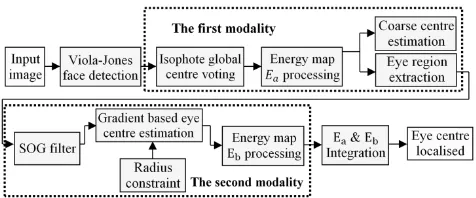
Fig. 1. An overview of the eye centre localisation algorithm chain
The algorithm includes two modalities. The first modality performs a global estimation of the eye centres over a face image and extracts the corresponding eye regions. Results from the first modality are fed into the second modality as prior knowledge and lead to a regional and more precise estimation of the eye centres. The two energy maps generated by the two modalities are fused to produce the final estimation of the eye centres. Note that the two modalities operate on a pre-detected face image. We employed the Viola-Jones face detector [23] to search for a face with a moderate head rotation in an image, which is most commonly seen in an active HCI session.
A. Isophote-based Global Centre Voting and Eye Detection Human eyes can be characterised as radially symmetrical patterns which can be represented by contours of equal intensity values in an image, i.e. isophotes [24]. Due to the large contrast between the iris and the sclera as well as that between the iris and the pupil, the isophotes that follow the edges of the iris and the pupil reflect the geometrical properties of the eye. Therefore the centres of these isophotes will be able to represent the estimated eye centres. An isophote-based algorithm enables pixels in an eye region to vote for the isophote centres they belong to [25]. The displacement vector pointing from a pixel to its isophote centre follows Eq. (1):
{𝐷𝑥, 𝐷𝑦} = −
{𝐼𝑥, 𝐼𝑦}(𝐼𝑥2 + 𝐼𝑦2)
𝐼𝑦2𝐼𝑥𝑥− 2𝐼𝑥𝐼𝑥𝑦𝐼𝑦+ 𝐼𝑥2𝐼𝑦𝑦 (1)
where 𝐼𝑥 and 𝐼𝑦 are first-order derivatives of the luminance function
𝐼(𝑥, 𝑦) in the 𝑥 and 𝑦 directions. 𝐼𝑥𝑥, 𝐼𝑥𝑦 and 𝐼𝑦𝑦 are the second-order
partial derivatives of the luminance function in the 𝑥 and 𝑦 directions. The importance of each vote is indicated by the curvedness of the isophote since the iris and pupil edges that are circular obtain high curvedness values as opposed to flat isophotes. The curvedness [26] is calculated as:
𝑐𝑑(𝑥, 𝑦) = √𝐼𝑥𝑥2 + 2 × 𝐼𝑥𝑦2 + 𝐼𝑦𝑦2 (2)
We also consider the brightness of the isophote centres in the voting process based on the fact that the pupil is normally darker than the iris and the sclera. Therefore, an energy map 𝐸𝑎(𝑥, 𝑦) is constructed that
collects all the votes to reflect the eye centre position following Eq. (3):
𝐸𝑎(𝑥 + 𝐷𝑥, 𝑦 + 𝐷𝑦) = [𝛼 − 𝐼(𝑥 + 𝐷𝑥, 𝑦 + 𝐷𝑦)] × 𝑐𝑑(𝑥, 𝑦) (3)
where 𝛼 is the maximum greyscale in the image (𝛼 = 255 in the experiments). Though isophotes have been employed by a number of methods, they have only been extracted from the eye regions which are either cropped according to anthropometric relations (which are interrupted by head rotations) or found by an eye detector (which largely increases the complexity of the algorithm). Our method is different, in that it extracts isophote features for the whole face and constructs a global energy map 𝐸𝑎(𝑥, 𝑦). The energy points that are
below 30% of the maximum value are removed. The remaining energy points therefore become the new eye centre candidates that are fed to
our second modality for further analysis. For the top-left and the top-right quarters of the energy map ( 𝐸𝑎𝑢𝑙(𝑥, 𝑦) and 𝐸𝑎𝑢𝑟(𝑥, 𝑦)), the energy
centres, i.e. the first moment divided by the total energy, are calculated and selected as the optimal eye centres. For example, 𝐸𝑎𝑢𝑙(𝑥, 𝑦) can
be calculated by Eq. (4):
{cx𝑎𝑢𝑙, cy𝑎𝑢𝑙} =
∑𝑚𝑥=1∑𝑛𝑦=1{𝑥, 𝑦} ∙ 𝐸𝑎𝑢𝑙(𝑥, 𝑦)
∑𝑚𝑥=1∑𝑛𝑦=1𝐸𝑎𝑢𝑙(𝑥, 𝑦) (4)
where 𝐶𝑎𝑢𝑙= {cx𝑎𝑢𝑙, cy𝑎𝑢𝑙} is the optimal estimation of the left eye
centre, 𝑚 and 𝑛 are the maximum row and column number in 𝐸𝑎𝑢𝑙.
The eye region to be analysed by our second modality is then selected which centres at the optimal eye centre estimation (its width being 1/10 of the face size and its height being 1/15 of the face size). As a result, our method does not require an eye detector and is robust to moderate head rotations since global isophotes are investigated. This process is shown in Fig. 2.
Fig. 2. An example of isophote-based eye centre detection. (a) The top-left quarter of a face image where an eye region and an eye centre is detected. (b) The corresponding curvedness image. (c) The displacement vector field. (d) The energy map.
B. Gradient-based Eye Centre Estimation
The first modality performs the initial eye centre estimation, filtering eye centre candidates and selecting local eye regions for the second modality. Based on an objective function (Eq. (5)), we further introduce a radius constraint and design a SOG filter to re-estimate the eye centre positions with enhanced accuracy and reliability.
The radially symmetrical patterns of the eye generate isophotes around the iris and pupil edges that can effectively vote for the eye centre. When simply modelled as circular objects, the iris and pupil can produce gradient features that give an accurate estimation of the eye centre. This is based on the idea that the prominent gradient vectors on the circular iris/pupil boundary should agree with the radial directions and therefore the dot product of each gradient vector with its corresponding radial vector is maximised. This model is formulated as an objective function [14]:
𝒄∗=arg 𝑚𝑎𝑥
𝒄 { 1
𝑁∑ ∑ 𝐼𝒄(𝑥, 𝑦) ∙ (𝒅𝑻 𝑛
𝑦=1 (𝑥, 𝑦) ∙ 𝒈(𝑥, 𝑦)) 2 𝑚
𝑥=1 } (5)
𝒅(𝑥, 𝑦) = 𝒑(𝑥, 𝑦) − 𝒄
‖𝒑(𝑥, 𝑦) − 𝒄‖2, ∀𝑥∀𝑦: ‖𝒅(𝑥, 𝑦)‖2= 1, ‖𝒈(𝑥, 𝑦)‖2= 1 (6)
where 𝒄 is the centre candidates, 𝒄∗ is the optimal centre, 𝑁 is the
number of pixels in the eye region to be analysed, 𝒅(𝑥, 𝑦) is the displacement vector connecting a centre candidate 𝒄 and 𝒑(𝑥, 𝑦)
which is any pixel different from 𝒄, 𝒈(𝑥, 𝑦) is the gradient vector on the edge point, 𝐼𝒄 is the intensity value at an isophote centre
and 𝑚 𝑎𝑛𝑑 𝑛 have the same definition as in the preceding subsection. The displacement vectors and gradient vectors are normalised to unit vectors. This objective function is then modified such that the direction of the gradient vector is only considered if it is reverse to the displacement vector based on the fact that the pupil is always darker than its neighbouring regions and thus generates outward gradients.
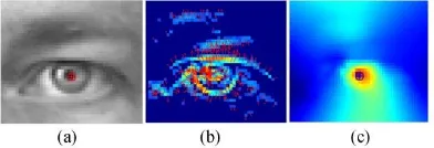
[image:3.612.318.559.247.315.2]Fig. 3. An example of gradient-based eye centre localisation. (a) An eye image. (b) Gradient magnitude image where the gradient directions are represented by arrows. Gradients with magnitude below 70% of the maximum are removed. (c) The resulting energy map.
While this modality provides an effective solution to eye centre estimation, it has a number of inherent limitations that would cause error or even failure in the estimation. These limitations are mainly caused by its sensitivity to other circular pixel clusters such as eye corners and shadows, as well as strong gradients on the eyelid and eyebrows which can be even exaggerated by the use of facial makeup. To resolve the above problems shared by most methods that utilise geometrical features for eye centre localisation, we introduce a radius constraint and design a SOG filter that effectively deal with the circularity measure and problems posed by eyebrows and eyelids.
C. Iris Radius Constraint
A radius constraint is introduced such that the Euclidean norms of the displacement vectors, which are related to the estimated iris radius, have more influence on the calculation of eye centre localisation. This is based on the assumption that the shadows and the eyebrow segments have random radius values, while the iris radii are more constant relative to the size of a face.
This provides a way to differentiate circular clusters of various radii and to determine their weights in the energy map accumulation. The function for the significance measure emulates the frequency response of a Butterworth low pass filter:
𝑟𝑤(𝑥, 𝑦) = √
1
1 + (‖𝒅(𝑥, 𝑦)‖2− 𝐷
𝜔 )
2𝜎
2 (7)
where ‖𝒅(𝑥, 𝑦)‖2 is the 𝐿2 norm of the displacement vector without
being normalised to a unit vector. D is the estimated radius of the iris. 𝜎
[image:4.612.328.548.489.688.2]and 𝜔 correspond to the order and the cutoff frequency of the filter. The curves corresponding to varying 𝜎 and 𝜔 following Eq. 7 are shown in Fig. 4. It should be noted that in each subfigure only one parameter is variable while the other remains constant.
Fig. 4. Significance measure of a SOG filter with different parameters. (a) Curves with varying 𝜎 (𝜎 = 1, 2 , 3) and constant 𝜔 (𝜔 = 2). (b) Curves with varying 𝜔 (𝜔 = 1, 2 , 3) and constant 𝜎 (𝜎 = 2).
The radius weight function is maximally flat around the estimated centre D and drops rapidly when the radius is out of the flatness band whose range is controlled by 𝜎. The roll-off rate is controlled by 𝜔, indicating the decreasing rate in weight. Increasing 𝜔 while decreasing
𝜎 will enhance the rigidity of the constraint which could be assumed
for circumstances where strong shadows are present. The value for D can be set according to the size of the face in an image. Therefore, the radius weight function allows adjustable coefficients that effectively alleviate the problematic issues posed by circular dark pixel clusters.
D. SOG Filter
A SOG filter is introduced that discriminates gradients of rapid change in orientation from those of less change. We specifically design this novel SOG filter and introduce it into the modular eye centre localisation scheme so that it is perfectly tailored to reinforce the two main modalities despite its versatile applicability.
The basic idea takes the form of a statistical analysis of the gradient orientations within a window centred at a pixel position. For each
𝐷𝑥× 𝐷𝑦 window centred at pixel 𝑖, the gradients in 𝑥 and 𝑦 directions
are calculated whose orientations follow:
𝑜𝑟𝑖𝑒𝑛𝑡𝐺 = tan−1(𝐼𝑦
𝐼𝑥)∙
180°
𝜋 (8)
The gradient orientations are then accumulated into 𝑘 (𝑘 < 360)
orientation bins, where each bin contains the count of the orientations from 𝑏 ∙360°𝑘 to (𝑏 + 1) ∙360°𝑘 (0 ≤ 𝑏 ≤ 𝑘 − 1) within the window. If the count recorded in a bin exceeds a threshold, the corresponding pixels that accumulate the bin will have their gradient vector halved, i.e. their weights reduced. As a result, the objective function becomes:
𝒄∗=arg 𝑚𝑎𝑥
𝒄 {1𝑁∑ ∑ 𝑠𝑤(𝑥, 𝑦) ∙ 𝑟𝑤(𝑥, 𝑦) ∙ [𝛼 − 𝐼(𝑥, 𝑦)] ∙ (𝒅𝑻
𝑛
𝑦=1 (𝑥, 𝑦) ∙ 𝒈(𝑥, 𝑦)) 2 𝑚
𝑥=1 } (9)
where 𝑠𝑤(𝑥, 𝑦) is the weight of the gradient adjusted by the SOG filter. The threshold for the counts is determined by an absolute value as well as a value relative to the number of pixels with non-zero gradients within the window. As a result, the pixels that maintain similar gradient orientations to their neighbours will have their weights reduced. Therefore the SOG filter can be used for general curvature discrimination tasks. It has the advantage that it does not require an explicit function for the curve and also it is effective in dealing with curves that form irregular shapes. Fig. 5 demonstrates the effectiveness of a SOG filter applied to different images of an eye region, with or without the presence of glass frames.
[image:4.612.52.285.560.652.2]Fig. 5(a) demonstrates that the SOG filter works effectively on images of eyes with eyeliner drawn, prominent eyebrows, overexposed nose regions, protruding eye pouch, and sharp edges caused by sunken eye profile. Fig. 5(b) demonstrates that it also works on images of eye regions occluded by glass frames of different colours, shapes and orientations. Note that in Fig. 5(b), the rightmost raw eye image is a rotated version (30 degrees) of its left one. We do not rely on the SOG filter to discriminate all the other edges from pupil and iris edges. While a SOG filter can remove most interfering gradient pixels, the gradient based modality will continue to analyse the remaining gradient features. This approach allows the magnitude and orientation of gradients to serve independently in obtaining representative features. It resolves the challenges brought by shadows, facial makeup and edges on the eyelids, eyebrows and other facial parts outside the iris that are most interfering in geometric feature based eye centre localisation approaches.
E. Energy Map Integration
In the final stage, the two energy maps 𝐸𝑎 and 𝐸𝑏 are integrated into
𝐸𝑓(𝑥, 𝑦) so that they both contribute to the election of the eye centre. It
is critical, prior to the integration, to determine the confidence of each modality, to estimate the complexity of the eye image, and thus to determine their weights in the fusion mechanism.
The left eye region is taken as an example to illustrate the fusion mechanism. If the equivalent centroid 𝐶𝑎𝑢𝑙calculated by Eq. (4) is
close to the pixel position 𝐶𝑚𝑎𝑥𝑙 that has the maximum value in the
first energy map 𝐸𝑎𝑢𝑙(𝑥, 𝑦), 𝐶𝑎𝑢𝑙 is considered confident since the
isophote centre and the equivalent centroid coincide. In this case, stronger gradients from the pupil/iris edges are present, allowing the second modality to be more robust and precise. The two modalities are then utilised and fused following Eq. (10). When 𝐶𝑎𝑢𝑙 and 𝐶𝑚𝑎𝑥𝑙
disagree and have a large Euclidean distance, the first energy map will have high energy clusters sparsely distributed, potentially caused by severe shadows and specularities. The second modality will be influenced by gradients outside the iris region and produce erroneous centre estimates. Therefore only the equivalent centroids 𝐶𝑎𝑢𝑙 and
𝐶𝑎𝑢𝑟 are selected to be the final eye centres.
𝐸𝑓(𝑥, 𝑦) = ‖𝐶 1
𝑎𝑢𝑙 − 𝐶𝐸𝑎𝑚𝑎𝑥‖2∙ 𝐸𝑎(𝑥, 𝑦) + 𝐸𝑏(𝑥, 𝑦) (10) where 𝜖 takes a value relative to the width of the eye region 𝜖𝑓 and
0 < ‖𝐶𝑎𝑢𝑙− 𝐶𝐸𝑎𝑚𝑎𝑥‖2≤ 𝜖. In our experiments, 𝜖 = 0.3𝜖𝑓 pixels.
The maximum response in the final energy map will represent the
estimated eye centre. The estimate for the final right eye centre follows the same procedure.
4. EYE CENTRE LOCALISATION EXPERIMENTS AND
RESULTS
Three publicly available databases were tested in our experiments: the BioID database [27], the GI4E database [16] and the extended Yale Face Database b [28]. The BioID database is the most widely employed database for eye centre localisation studies since it contains an array of variations including illumination, face scale, moderate head pose and the presence of glasses; The GI4E database is known for containing images of 103 subjects with 12 different gaze directions; The extended Yale Face Database b is captured under extremely challenging lighting conditions and also contains various head poses. Since the proposed method is geometric feature/model based and is unsupervised, it does not attempt to deal with images where pupil/iris regions are invisible. Therefore, we experimented on a subset of the extended Yale Face Database b where the absolute azimuth and elevation angles are no larger than 40 degrees such that the periocular regions are not completely shadowed.
The relative error measure proposed by [29] was used to evaluate the accuracy of the proposed algorithm. It firstly calculates the absolute error (i.e. Euclidian distance between centre estimates and ground truth provided by the database) and then normalises the Euclidian distance relative to the pupillary distance. This is formulated by Eq. (11):
𝑒 = max(𝑑𝑙𝑒𝑓𝑡, 𝑑𝑟𝑖𝑔ℎ𝑡)
𝜔 (11)
where 𝑑𝑙𝑒𝑓𝑡 and 𝑑𝑟𝑖𝑔ℎ𝑡 are the absolute errors for the eye pair, and 𝜔
is the pupillary distance. The maximum of 𝑑𝑙𝑒𝑓𝑡 and 𝑑𝑟𝑖𝑔ℎ𝑡 after
normalisation is defined as ‘max normalised error’ 𝑒𝑚𝑎𝑥. Additionally,
the accuracy curve for the minimum normalised error 𝑒𝑚𝑖𝑛 and the
average normalised error 𝑒𝑎𝑣𝑔 are calculated. A relative distance of
𝑒 = 0.25 corresponds to half the width of an eye.
[image:5.612.74.538.539.695.2]
The evaluations on the BioID database are shown in Fig. 6 and are further compared with 10 state-of-the-art methods in the literature, summarised in Table 1.
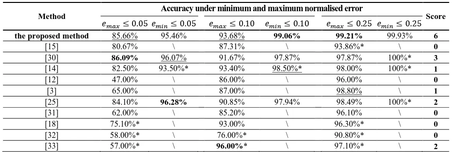
Table 1. Comparison of the Accuracy for Eye Centre Localisation on the BioID Databasea
Method
Accuracy under minimum and maximum normalised error
Score 𝑒𝑚𝑎𝑥≤ 0.05𝑒𝑚𝑖𝑛≤ 0.05 𝑒𝑚𝑎𝑥≤ 0.10 𝑒𝑚𝑖𝑛≤ 0.10 𝑒𝑚𝑎𝑥≤ 0.25 𝑒𝑚𝑖𝑛≤ 0.25
the proposed method 85.66% 95.46% 93.68% 99.06% 99.21% 99.93% 6
[15] 80.67% \ 87.31% \ 93.86%* \ 0
[30] 86.09% 96.07% 91.67% 97.87% 97.87% 100%* 3
[14] 82.50% 93.50%* 93.40% 98.50%* 98.00% 100%* 1
[12] 47.00% \ 86.00% \ 96.00% \ 0
[3] 65.00% \ 87.00% \ 98.80% \ 1
[25] 84.10% 96.28% 90.85% 97.94% 98.49% 100%* 2
[31] 62.00% \ 85.20% \ 96.10% \ 0
[18] 75.10%* \ 93.00% \ 96.30%* \ 0
[32] 58.00%* \ 76.00%* \ 90.80%* \ 0
[33] 57.00%* \ 96.00%* \ 97.10%* \ 2
aThose with a ‘*’ notation are not explicitly provided by the authors but are measured from the accuracy curves available. Those with a ‘\’ notation are
Fig. 8. Evaluation result on a subset of the extended Yale Face Database b. (a) Representative eye regions in the subset with challenging illumination (when the azimuth and elevation angles are no larger than 40 degrees). (b) Representative eye regions not included in the subset (when the azimuth and elevation angles are larger than 40 degrees). (c) Accuracy curves for different error measures.
Fig. 6. Accuracy curves of the proposed method on the BioID database
Fig. 7. Accuracy curves of the proposed method on the GI4E database, in comparison with 6 other methods.
The proposed method gains the best results for the accuracy measure 𝑒𝑚𝑖𝑛≤ 0.10 as well as 𝑒𝑚𝑎𝑥≤ 0.25, and the second best for
𝑒𝑚𝑎𝑥≤ 0.05 and 𝑒𝑚𝑎𝑥≤ 0.10. Except for the accuracy measure for
𝑒𝑚𝑖𝑛≤ 0.25 where very similar results are achieved, a score of 2 is
assigned to every first rank and a score of 1 is assigned to every second rank. The proposed method gains a total score of 6, outperforming all the other methods when comparing the classification accuracy.
Further evaluations on the GI4E database are compared to 6 other methods (similarly to [16] and [34]), as shown in Fig. 7. Outperforming all the other methods in comparison, the proposed method proves to be robust against eye movement by achieving 97.9% accuracy for 𝑒𝑚𝑎𝑥≤ 0.05. Tests on a subset of the extended Yale Face
Database b also reflect that the proposed method can maintain high accuracy on 8 different head poses and challenging lighting conditions as long as pupil/iris regions are not entirely shadowed. These results can be found in Fig. 8.
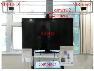
Apart from tests on the three publically available databases, we conducted an additional set of experiments on data captured out of laboratory environments. We have designed a data capture system, shown in Fig. 9, intended to gather facial data in real-world environments. The design of the system consists of 1) a high-definition (HD) 47-inch display, 2) a webcam (referred to as camera 1 in the rest of the paper) operating at 640×480 resolution, 3) two near-infrared (NIR) illuminators (SFH4232 with 850 nm wavelength) used to create controllable yet challenging lighting conditions, 4) a Point Grey GS3-U3-41C6NIR-C camera (referred to as camera 2 in the rest of the paper) operating at 2048×800 resolution, with a 850nm +/-5nm NIR band pass filter and 5) a PC in the cabinet for camera and illuminator control and data storage/processing. The cameras are 2.1 metres from the floor and the NIR illuminators are both 0.75 metres from the cameras.
The data capture process is described as follows:
1) The data capture system was placed at a university public kitchen area and then at a library foyer. A total number of 172 volunteers participated in the experiment during 6 recording sessions.
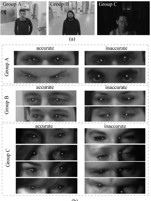
2) Every volunteer was asked to stand at 1 metre away from the display and look at the centre of the display while his/her face image was recorded by camera 1. These facial data are referred to as ‘Group A’ data in the rest of the paper.
3) Every volunteer was then asked to look at the top-right corner of the display while his/her face image was recorded by camera 1. These facial data are referred to as ‘Group B’ data in the rest of the paper.
4) Lastly, every volunteer was asked to look at the far left side of the display while his/her face image was recorded by camera 2. One of the two NIR illuminators was randomly selected and switched on during this experiment. In this part of the experiment, the NIR illuminator was the sole provider of illumination. These facial data are referred to as ‘Group C’ data in the rest of the paper.
5) The eye centre positions for all the facial images were then manually labelled as the ground truth for algorithm validation.
It should be noted that all the volunteers were asked to behave naturally, i.e. they were allowed to perform head movement, eye movement or a combination of both when they changed their eye gaze. The use of NIR lights allows us to simulate insufficient and uneven illumination conditions, which introduces shadows and specularities.
Fig. 9. The data capture system structure
[image:6.612.57.289.199.335.2] [image:6.612.362.523.546.668.2]Fig. 10. Representative results on the self-collected dataset. (a) Sample images from Group A, B and C data. (b) Representative examples of accurately and inaccurately localised eye centres.
[image:7.612.55.291.508.722.2]It can be seen from Fig. 10 that our algorithm is able to deal with images captured under poor illumination conditions where severe shadows and specularities are present. Only when the iris and pupil regions are completely shadowed or occluded will they cause false identifications of eye centres. In Fig. 11, we further summarise the eye centre localisation results in the form of accuracy curves for a total number of 516 images.
Fig. 11. Accuracy curves for (a) ‘Group A’ data, (b) ‘Group B’ data, and (c) ‘Group C’ data. (d) Accuracy curve for the BioID database as a reference.
Fig. 11(a) and (b) show that the proposed algorithm maintains high accuracy with ‘Group A’ and ‘Group B’ data where the interfering variations include long camera-subject distance, head pose and eye movement. All the curves representing the maximum error, the minimum error and the average error under realistic scenes are comparable to those generated from the BioID database (Fig. 11(d)). Fig. 11(c) corresponds to the experiment where the NIR illuminator deliberately created challenging self-cast shadows, resulting in at least one pupil and/or iris in every image being obscure or even invisible. This accounts for the declined accuracy shown by the curve of the maximum error. Nevertheless, the robustness of the proposed method is validated by the curve of the minimum error, which indicates that even under poor illumination conditions, at least one eye centre in every image is localised with extremely high accuracy.
As the proposed eye centre localisation algorithm exhibits high accuracy and robustness under real-world scenarios, we further design a gaze gesture recognition algorithm, intended to boost HCI experience.
5. GAZE GESTURE CONTROL FOR HUMAN COMPUTER
INTERACTION
A. Gaze Gesture Recognition
Gaze gestures are predefined sequences of eye movements which hold great potential in HCI. It has been proposed in the literature for disability assistance and other HCI purposes [37,38]. The realisation of remote control of a HCI system via gaze gestures is non-invasive, low-cost and efficient, involving 4 main stages: accurate eye centre localisation in the spatial-temporal domain, eye movement encoding [20], gaze gesture recognition [39] and HCI event activation.
In this paper, we employ the algorithm introduced in section 3 for accurate and robust eye centre localisation in the first stage. We did not employ any tracking based techniques since facial features can be dramatically influenced by user-camera distance, head pose and other factors, which would cause tracking failures that cannot be detected and restored easily. Performing the eye centre localisation algorithm on individual frames ensures that erroneous estimations in one image frame will have negligible impact on subsequent frames.
For every image frame in a video, two eye centre positions
𝐸𝑙(𝑓) = {𝑒𝑙𝑥, 𝑒𝑙𝑦} and 𝐸𝑟(𝑓) = {𝑒𝑟𝑥, 𝑒𝑟𝑦} are estimated and
recorded. The mean value of them is calculated as 𝐸̅(𝑓) = {𝑒̅𝑥, 𝑒̅𝑦},
where 𝑓 is the frame number and the 𝑥 and 𝑦 notations stand for the horizontal and vertical components. In the second stage, the first order derivatives of the vectors 𝑬𝒍, 𝑬𝒓and 𝑬̅are calculated as 𝑮𝒍(𝑓) =
{𝑒𝑙𝑥′, 𝑒𝑙𝑦′}, 𝑮𝒓(𝑓) = {𝑒𝑟𝑥′, 𝑒𝑟𝑦′} and 𝑮̅(𝑓) = {𝑒̅𝑥′, 𝑒̅𝑦′}, respectively.
A threshold (4.5 % in the experiments) is then set to remove any small values in the two vectors, which might be caused by unintentional saccadic movements. It should be noted that the threshold is
normalised by the pupillary distance
(𝑃𝑑= √(𝑒𝑙𝑥− 𝑒𝑟𝑥)2+ (𝑒𝑙𝑦− 𝑒𝑟𝑦)2) so that it is independent of
user-to-camera distance. Additionally, the movements of the two eyes are compared with regard to their magnitudes according to Eq. (12).
𝑅𝑔=
{
log10
(
√𝑒𝑙𝑥′2+ 𝑒𝑙𝑦′2
√𝑒𝑟𝑥′2+ 𝑒𝑟𝑦′2)
, 𝑖𝑓√𝑒𝑙𝑥′2+ 𝑒𝑙𝑦′2≥ 1 & √𝑒𝑙𝑥′2+ 𝑒𝑙𝑦′2≥ 1
0 , 𝑜𝑡ℎ𝑒𝑟𝑤𝑖𝑠𝑒
(12)
Only when the ratio 𝑅𝑔 is under a threshold (0.6 in the experiments)
are the eye centre positions updated by those from the subsequent frame. If we decompose 𝑮̅(𝑓) into 𝑮̅̅̅̅(𝑓) = 𝑒̅𝒙 𝑥′ and 𝑮̅̅̅̅(𝑓) = 𝑒̅𝒚 𝑦′ , a
positive value in 𝑮̅̅̅̅(𝑓)𝒙 is denoted by ‘1’, a negative value by ‘2’; a
positive value in 𝑮̅̅̅̅(𝑓)𝒚 is denoted by ‘4’ and a negative value by ‘7’.
[image:7.612.318.562.639.683.2]two gaze shift vectors 𝑮̅̅̅̅(𝑓)𝒙 and 𝑮̅̅̅̅(𝑓)𝒚 and produce 𝑮̅̅̅(𝑓)𝒔 , the
[image:8.612.49.301.116.360.2]integrated gaze shift vector. We define in the experiments for HCI 7 types of gaze gestures, shown in Table 2.
Table 2. Definition of 7 Types of Gaze Gestures for HCIa
Gesture No.
Gesture
Sequence Gesture Pattern Gesture Name
1 1 → 2 → 4 → 7 Top-left gaze
2/3/4
2 → 1 → 4 → 7/ 1 → 2 → 7 → 4/
2 → 1 → 7 → 4
Similar to Gesture No. 1
Top-right gaze/
Bottom-left gaze/ Bottom-right gaze
5 1 → 2 → 1 → 2 Reset gaze
6 4 → 7 → 4 → 7 Zoom-in gaze
7
2 → 4 → 1 → 7 4 → 1 → 7 → 2 1 → 7 → 2 → 4 7 → 2 → 4 → 1
Change-content gaze
aA ‘★’ denotes the starting position of a gaze gesture and a ‘•’ denotes the
end of a gaze gesture; the circled numbers represent the encoded gaze shifts; the arrows denote saccadic strokes.
In the third stage, the gaze gesture patterns are recognised by searching for specific gesture sequences in 𝑮̅̅̅(𝑓)𝒔 , which will trigger
pre-defined HCI events in the last stage.
B. Gaze Gestures for HCI
[image:8.612.317.558.626.739.2]Digital signage systems have been prevalent for years in this digital era and the information age. Their use for advertising has become ubiquitous and can be found at venues such as restaurants, shopping malls, airports and other public spaces. Often referred to as digital out-of-home (DOOH) advertising [40,41], this advertising format aims to extend the exposure and the effectiveness of marketing messages by engaging consumers to an increased extent, compared to conventional print based billboards [42]. Following the idea of switching from print media to digital media, it is only intuitive to reform a conventional DOOH advertising system toward a HCI system [43] for enhanced interactivity and adaptability. To this end, we have designed an experimental interactive advertising system as our case study for algorithm test. The design of the system follows the same structure as our data capture system introduced in the previous section (Fig. 9), where the HD display acts as a billboard capable of displaying an advertisement.
Fig. 12. An example of triggering the interactive advertising system with ‘type 2’ and ‘type 6’ gaze gestures (see Visualisation1).
As demonstrated by Fig. 12, when an individual approaches the system, the proposed algorithm detects his/her face from the images
captured by the webcam. It then performs eye centre localisation and gaze gesture analysis on the face images to decide on the advertisement display. Advertisement thumbnails are brought to random circulation when no face appears in a frame. If the user interacts with the system by issuing a gaze gesture, the advertisement display mode will be altered accordingly. For example, when gaze gesture No. 2 is detected, the top-right advertisement thumbnail will be displayed at the screen centre. When gaze gesture No. 6 is detected as a subsequent gesture, an enlarged view of the centred thumbnail becomes available. This puts the user in an active role for being able to receive the recommended advertisements from the system as well as being able to browse or switch the advertisements oneself. The mean eye centre coordinates 𝐸̅(𝑓) can be recorded over time to reflect the relative attentiveness of a user. In our tests, the system can robustly, accurately and in real time perform advertisement selection (gaze gesture type 1, 2, 3, 4, 7), reset (gaze gesture type 5) and zoom-in (gaze gesture type 6). Any gaze gesture can be recognised as soon as the last eye saccade in a gaze gesture sequence is issued by a user (efficiency discussed in Section 6.A.5).
The contactless gaze control method developed from our novel eye centre localisation algorithm is not only beneficial to the interactive advertising system, but it has great potential in the assistance of the disabled and the elderly who cannot easily manipulate HCI systems at public venues such as airports, train stations and shopping malls.
6. DISCUSSION
A. The Benefits Brought by All the Modules in the Eye Centre Localisation Method
1. A Built-in Eye Detector
As stated previously, the first modality computes an energy map for a whole face region (different from other isophote feature based methods that generate energy maps only for a pre-located eye region), and then reveals an eye centre candidate by calculating the energy centre. A rectangular region around the estimated centre location is cropped as the eye region that is fed to the second modality for a regional analysis. As a result, the first modality provides a built-in eye detector that can not only interact with the second modality, but can be applied more generally to other eye detection tasks.
2. Tolerance to Head Poses
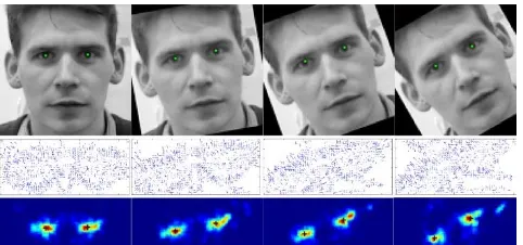
Also benefiting from the first modality, the tolerance to head poses is embedded in the global analysis. When head rotation occurs, the relative eye position on a face changes dramatically and breaks the anthropometric relations set for a frontal face. Therefore, the extraction of a local facial region according to facial geometries can no longer ensure that it contains a complete eye region. This however has minimal influence on the proposed method since the true eye centre candidates always reside in the global energy map. An example is shown in Fig. 13 where eye centres are accurately localised on a face image manually rotated by 10, 20 and 30 degrees.
[image:8.612.49.290.639.714.2]3. Tolerance to Shadows
The iris radius constraint drastically lowers the impacts (weights) of shadowed pixels even when they feature dark circular regions that resemble pupil/iris regions. This is facilitated by the prior knowledge that the size of a pupil/iris is a relative constant, compared to shadows of random radii. Therefore, when the radius of a dark circular region deviates from the pre-defined constant, the weights of the votes from this region should be diminished. However, the proposed method can be undermined by images where the pupil/iris regions are almost invisible (e.g. completely shadowed). This is because the proposed method is unsupervised and is intended to explore geometric features from the periocular regions. This limitation can be compensated by employing systems similar to that in Fig. 9 to provide active illumination. Another possible solution is to utilise a classifier trained with poorly illuminated face/eye images to explore anthropometric relations or face appearance features.
4. Tolerance to Interfering Facial Edges
The SOG filter is what brings more robustness to the proposed algorithm in that it is able to measure the gradient similarity of any regular or irregular shape. The idea is based on the fact that the pupil/iris edges should be largely curved. Other gradients, regardless of their magnitudes, are more likely to be produced by shape edges from eyebrows, shadows and face accessories. The SOG filter results in a reduction of edges that have similar gradient directions, determined by means of statistical analysis.
5. Superior Efficiency
We demonstrate the simplicity and efficiency of the proposed method by comparing it to [14] which claims to have achieved excellent real-time performance as one of its key features. Take the image containing a 41 × 47 eye region, i.e. 1927 pixels, as an example (Fig. 3), [14] performs per-pixel estimation of the eye centre, assuming that every pixel is an eye centre candidate. Therefore 1927 iterations are needed before the optimal candidate is selected. The proposed method, on the other hand, resolves the problem by utilising the prior knowledge drawn from the first modality which, through an initial estimation, avoids the per-pixel candidate assumption. The removal of the low-energy pixels in the first modality largely reduced the number of candidates, i.e. number of iterations in the second modality. In the
[image:9.612.51.292.535.639.2]41 × 47 eye region, the iterations are decreased to only 67 from 1927, making our algorithm 29 times faster.
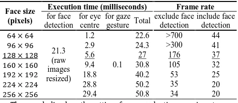
Table 3. The Efficiency of the Proposed Algorithma
Face size (pixels)
Execution time (milliseconds) Frame rate
for face detection
for eye centre
for gaze gesture Total
exclude face detection
include face detection 64 × 64
21.3 (raw images resized)
1.2
0.1
22.6 >700 44
96 × 96 2.9 24.3 >300 41
128 × 128 5.6 27 176 37
160 × 160 9.4 30.8 105 32 192 × 192 18.8 40.2 53 25 224 × 224 28.8 50.2 35 20 256 × 256 29.4 50.8 34 20
aThose underlined are the settings for our evaluation experiments
We further tested the proposed algorithm with Microsoft Visual Studio 2012 and the OpenCV library on a computer with an Inter(R) Core(TM) i5-4570 CPU and 12G memory. The average execution time is calculated for every frame of a video (150 frames in total) recorded by a webcam at 640 × 480 resolution and at 30 frames per second. These results can be found in Table 3. Note that for face detection, the raw images were resized to a uniform size of 320 × 240 pixels, given the fact that the Viola-Jones detector was trained on small face images. However, the detected face regions are cropped from the raw images and were resized to 7 different sizes for evaluating their respective
computational cost. Our evaluation experiments on all the databases employed face regions resized to 128 × 128 and obtained superior results. The frame rate of 37 frames per second in this setting ensures that the proposed algorithm can run in real time.
B. the Interactive Advertising System
As our case study, the interactive advertising system has fulfilled two tasks: 1) capture of 3 groups of facial data, and 2) HCI implementation and test.
For data capture, this system can create various controllable illumination conditions that can be evaluated independently or analysed in a comparative manner.
For HCI, it allows a user to actively interact with the system by issuing up to 7 types of gaze gestures. In the case where a group of individuals are recognised by the system, the one individual that is the closest to the system (the one with the largest pupillary distance in the image) obtains the highest priority in controlling the system. More generally, other different gaze gestures can be designed to suit an individual HCI application. Users can then manipulate virtual objects on a screen (e.g. switch TV channels or turn up the speaker) or browse specific content (e.g. an interactive map or an electronic brochure).
7. CONCLUSION
This paper introduces a novel method for eye centre localisation and gaze gesture recognition which is intended for use in gathering human behavioural data for enabling a better HCI experience. The main contributions of our method include the following algorithm designs and system developments: 1) a modular eye centre localisation method consisting of two modalities, an iris radius constraint and a SOG filter, 2) communication through initiation of gaze gestures and employment of a gaze gesture recognition algorithm, and 3) development of an experimental HCI system.
Tested on the BioID database and the GI4E database, our method has obtained the highest accuracy, outperforming 10 other methods and 6 other methods, respectively. Evaluations on a subset of the extended Yale Face Database b also demonstrated the robustness of the proposed method against illumination and moderate head pose variations. Moreover, we designed a data capture system and gathered three groups of facial data under realistic scenes where we further introduced challenging environmental variations. Results from these data have again validated the high accuracy and robustness of the proposed eye centre localisation method. To test our algorithms from an applied point of view, the data capture system is further developed into an experimental HCI system, which creates a user-centred HCI environment. Users are able to effortlessly and remotely browse and switch content displayed on the screen by issuing up to 7 types of gaze gestures. This HCI system (Fig. 9) is configured in such a way that it allows for future development to provide enhanced intelligence and interactivity. In our future work, we will fully employ the NIR illuminators to develop a synchronised system that is able to gather 2D facial data as well as recovering 3D facial data. This will afford great potential for increased accuracy for eye centre localisation and gaze gesture control. In addition, it will allow us to explore other facial attributes by utilising a combination of 2D and 3D features, which collectively can lead to multi-functional HCI systems with higher usability and intelligence. Overall, the methods introduced in this paper contribute theoretically to the research in eye centre localisation and gaze analysis; as well as demonstrating their potential for providing a richer HCI experience.
REFERENCES:
2.A. Kapoor, W. Burleson, and R.W. Picard, “Automatic prediction of frustration,” International journal of human-computer studies 65, 724-736 (2007).
3.B. Kroon, A. Hanjalic, and S.M. Maas, “Eye localization for face matching: is it always useful and under what conditions?,” in
Proceedings of the 2008 international conference on Content-based
image and video retrieval (ACM, 2008), pp. 379-388.
4.A. Tawari, K.H. Chen, and M.M. Trivedi, “Where is the driver looking: Analysis of head, eye and iris for robust gaze zone estimation,” in
Proceedings of the17th International IEEE Conference on Intelligent
Transportation Systems (IEEE, 2014), pp. 988-994.
5.M. Vidal, J. Turner, A. Bulling, and H. Gellersen, “Wearable eye tracking for mental health monitoring,” Computer Communications 35, 1306-1311 (2012).
6.E. Li, J. Breeze, M. Horsley, and D.A. Briely, “Private and Public: Eye Movement and Eye Tracking in Marketing,” in Current Trends in Eye
Tracking Research (Springer, 2014), pp. 201-209.
7.T. Toyama, T. Kieninger, F. Shafait, and A. Dengel, “Gaze guided object recognition using a head-mounted eye tracker,” in Proceedings of
the Symposium on Eye Tracking Research and Applications (ACM,
2012), pp. 91-98.
8.J.D. Morgante, R. Zolfaghari, and S.P. Johnson, “A critical test of temporal and spatial accuracy of the Tobii T60XL eye tracker,” Infancy 17, 9-32 (2012).
9.Z. Zhu and Q. Ji, “Robust real-time eye detection and tracking under variable lighting conditions and various face orientations,” Computer Vision and Image Understanding 98, 124-154 (2005). 10.J. G. Daugman, “High confidence visual recognition of persons by a
test of statistical independence,” IEEE Transactions on Pattern Analysis and Machine Intelligence 15, 1148-1161 (1993).
11.M. Barbosa and A. C. James, “Joint iris boundary detection and fit: a real-time method for accurate pupil tracking,” Biomedical optics express 5, 2458-2470 (2014).
12.M. Asadifard, and J. Shanbezadeh, “Automatic adaptive center of pupil detection using face detection and cdf analysis,” in Proc. International MultiConference of Engineers and Computer Scientists
(IAENG, 2010), 3.
13.M. Türkan, M. Pardas, and A.E. Cetin, “Human eye localization using edge projections,” presented at the International Conference on Computer Vision Theory and Applications, Barcelona, Spain, 8-11 March, 2007.
14.F. Timm, and E. Barth, “Accurate Eye Centre Localisation by Means of Gradients,” presented at the International Conference on Computer Vision Theory and Applications, Algarve, Portugal, 5-7 March, 2011.
15.M. Leo, D. Cazzato, T. De Marco, and C. Distante, “Unsupervised Eye Pupil Localization through Differential Geometry and Local Self-Similarity Matching,” PloS one 9, e102829 (2014).
16.A. Villanueva, V. Ponz, L. Sesma-Sanchez, M. Ariz, S. Porta, and R. Cabeza, “Hybrid method based on topography for robust detection of iris center and eye corners,” ACM Transactions on Multimedia Computing, Communications, and Applications9, 25 (2013). 17.H. J. Kim and W. Y. Kim, “Eye detection in facial images using
Zernike moments with SVM,” ETRI journal 30, 335-337 (2008). 18.Z. Niu, S. Shan, S. Yan, X. Chen, and W. Gao, “2D cascaded Adaboost
for eye localization,” in Proceedings of the 18th International
Conference on Pattern Recognition (IEEE, 2006), pp. 1216-1219.
19.X. Zhu, and D. Ramanan, “Face detection, pose estimation, and landmark localization in the wild,” in Proceedings of 2012 IEEE
Conference on Computer Vision and Pattern Recognition (IEEE,
2012), pp. 2879-2886.
20.H. Drewes, A.D. Luca, and A. Schmidt, “Eye-gaze interaction for mobile phones,” in Proceedings ofthe 4th international conference on mobile technology, applications, and systems and the 1st international symposium on Computer human interaction in mobile technology
(ACM, 2007), pp. 364-371.
21.A. Hyrskykari, H. Istance, and S. Vickers, “Gaze gestures or dwell-based interaction?,” in Proceedings of the Symposium on Eye
Tracking Research and Applications (ACM, 2012), pp. 229-232.
22.D. Rozado, F.B. Rodriguez, and P. Varona, “Low cost remote gaze gesture recognition in real time,” Applied Soft Computing 12, 2072-2084 (2012).
23.P. Viola and M. J. Jones, “Robust real-time face detection,” International journal of computer vision 57, 137–154 (2004). 24.J. Lichtenauer, E. Hendriks, and M. Reinders, “Isophote properties as
features for object detection,” in Proceedings of IEEE Computer Society Conference on Computer Vision and Pattern Recognition
(IEEE, 2005), pp. 649-654.
25.R. Valenti and T. Gevers, “Accurate eye center location and tracking using isophote curvature,” in Proceedings of IEEE Conference on
Computer Vision and Pattern Recognition (IEEE, 2008), pp. 1-8.
26.J.J. Koenderink and A.J.v. Doorn, “Surface shape and curvature scales,” Image and vision computing 10, 557-564.
27.BioID Technology Research, “BioID Face Database,” https://www.bioid.com/About/BioID-Face-Database.
28.A. S. Georghiades, P. N. Belhumeur, and D. J. Kriegman, “From few to many: Illumination cone models for face recognition under variable lighting and pose,” IEEE Transactions on Pattern Analysis and Machine Intelligence23, 643-660 (2001).
29.O. Jesorsky, K.J. Kirchberg, and R.W. Frischholz, “Robust face detection using the hausdorff distance,” Audio-and video-based
biometric person authentication (Springer, 2001), pp. 90-95.
30.R. Valenti and T. Gevers, “Accurate eye center location through invariant isocentric patterns,” IEEE Trans. Pattern Anal. Mach. Intell. 34, 1785-1798 (2012).
31.P. Campadelli, R. Lanzarotti, and G. Lipori, “Precise eye localization through a general-to-specific model definition,” in Proceedings of
British Machine Vision Conference (BMVA Press, 2006), pp. 187-196.
32.M. Hamouz, J. Kittler, J.K. Kamarainen, P. Paalanen, H. Kalviainen, and J. Matas, “Feature-based affine-invariant localization of faces,”
IEEE Trans. Pattern Anal. Mach. Intell.27, 1490-1495 (2005).
33.D. Cristinacce, T.F. Cootes, and I.M. Scott, “A Multi-Stage Approach to Facial Feature Detection,” in Proceedings of British Machine Vision
Conference (BMVA Press, 2004), pp. 1-10.
34.S. J. Baek, K. A. Choi, C. Ma, Y. H. Kim and S. J. Ko, “Eyeball model-based iris center localization for visible image-model-based eye-gaze tracking systems,” IEEE Transactions on Consumer Electronics 59, 415-421 (2013).
35.J. Daugman, “How iris recognition works,” IEEE Transactions on Circuits and Systems for Video Technology 14, 21-30 (2004). 36.J. G. Wang, E. Sung, and R. Venkateswarlu, “Estimating the eye gaze
from one eye,” Computer Vision and Image Understanding 98, 83-103 (2005).
37.J.O. Wobbrock, J. Rubinstein, M.W. Sawyer, and A.T. Duchowski, “Longitudinal evaluation of discrete consecutive gaze gestures for text entry,” in Proceedings of the 2008 symposium on Eye tracking
research & applications (ACM, 2008), pp. 11-18.
38.D. Rozado, J.S. Agustin, F.B. Rodriguez, and P. Varona, “Gliding and saccadic gaze gesture recognition in real time,” ACM Transactions on
Interactive Intelligent Systems (ACM, 2012), 10.
39.H. Drewes and A. Schmidt, “Interacting with the computer using gaze gestures,” in Human-Computer Interaction–INTERACT 2007
(Springer, 2007), pp. 475-488.
40.P. Lasinger and C. Bauer, “Situationalization, the New Road to Adaptive Digital-out-of-Home Advertising,” in Proceedings of IADIS
International Conference e-Society (IADIS, 2013), pp. 162-169.
41.U. Stalder, “Digital Out-of-Home Media: Means and Effects of Digital Media in Public Space,” in Pervasive Advertising (Springer, 2011), pp. 31-56.