Asymmetric Bounded Neural Control for an
Uncertain Robot by State Feedback and Output
Feedback
Linghuan Kong, Wei He,
Senior Member, IEEE,
Yiting Dong,
Student Member, IEEE,
Long Cheng,
Senior
Member, IEEE,
Chenguang Yang,
Senior Member, IEEE,
Zhijun Li,
Senior Member, IEEE
Abstract
—In this paper, an adaptive neural bounded control
scheme is proposed for an
n-link rigid robotic manipulator with
unknown dynamics. With combination of neural approximation
and backstepping technique, an adaptive neural network control
policy is developed to guarantee the tracking performance of
the robot. Different from the existing results, the bounds of the
designed controller are known
a priori
, and they are determined
by controller gains,
making them applicable within actuator
limitations
. Furthermore, the designed controller is also able
to compensate the effect of unknown robotic dynamics. Via
Lyapunov stability theory, it can be proved that all the signals
are uniformly ultimately bounded (UUB). Simulations are carried
out to verify the effectiveness of the proposed scheme.
Index Terms
—Neural networks, Asymmetrically bounded
in-puts, A robotic manipulator, Adaptive control
I. I
NTRODUCTIONRobots have a wide range of applications in various fields
such as prospecting, navigation, aviation and so on [1]–[8].
Control design and stability analysis for a robot are
increas-ingly important and have received considerable attention [9],
[10]. A significant topic in the robot field is trajectory tracking
[11]. Thus, many research results have been obtained in the
past decades [12]–[14]. However, an avoidable challenge for
controller design is that there exists model uncertainty due to
the fact that robots are highly nonlinear and strongly coupled
[15]–[18].
Model-based control has been proved to be effective in
practical applications. An inevitable shortcoming for
model-This work was supported in part by the National Natural Science Foundation of China under Grant 61873298, Grant 61873268, Grant 61633016, Grant 61751310 and Grant 61573147, in part by the Anhui Science and Technology Major Program under Grant 17030901029, in part by the Beijing Science and Technology Project (Grant No. Z181100003118006), in part by the Beijing Municipal Natural Science Foundation (Grant No. L182060), and in part by the Engineering and Physical Sciences Research Council (EPSRC) under Grant EP/S001913.
L. Kong and W. He are with School of Automation and Electrical Engineer-ing, University of Science and Technology BeijEngineer-ing, Beijing 100083, China, and also with the Institute of Artificial Intelligence, University of Science and Technology Beijing, Beijing 100083, China. (Email: weihe@ieee.org)
Y. Dong is with the Department of Mechanical Engineering, Texas Tech University, Lubbock, TX 79409, USA.
L. Cheng is with the State Key Laboratory of Management and Control for Complex Systems, Institute of Automation, Chinese Academy of Sciences, Beijing 100190, China, and also with the University of the Chinese Academy of Sciences, Beijing 100049, China.
C. Yang is with Bristol Robotics Laboratory, University of the West of England, Bristol, BS16 1QY, UK.
Z. Li is with Department of Automation, University of Science and Technology of China, Hefei, China.
nonstrict-feedback systems with input saturation. In [70], a novel
adap-tive sliding mode controller is designed for Takagi-Sugeno
fuzzy systems with actuator saturation and system uncertainty.
An asymmetric saturation situation may be encountered if
the actuators partially loss their effectiveness for an uncertain
robot, due to motor fault, change of mechanical structure, etc,
which drives us to solve the asymmetric saturation constraint
problems for an uncertain robot. In [66]–[70], the bounds of
the designed controller are considered to be unknown for the
controller design, which motivates us to further investigate the
adaptive neural network control with asymmetric and known
bounds for an
n
-link rigid robotic manipulator with uncertain
dynamics, making the designed controller applicable within
actuator limitations.
Motivated by above observations, this paper focuses on
the adaptive bounded control for an
n
-link rigid robotic
manipulator with unknown dynamics, where the bounds of
the designed controller are asymmetric and known
a prior
and
furthermore can be predetermined by changing control gains,
making the designed controller applicable within actuator
limitations
. Neural networks are employed to approximate
unknown robotic dynamics. A high-gain observer is introduced
to estimate the immeasurable states.
Compared with the previous works, the main contributions
are summarized as follows:
1) Compared with [66]–[70], a main feature in this paper is
that the bounds of the designed controller are asymmetric
and known
a priori
, and furthermore they are
predeter-mined by changing control gains.
2) In [66], an additional auxiliary variable is designed to
eliminate the effect of input saturation. Compared with
[66], we directly adopt hyperbolic tangent function
tan-h
(
·
)
to obtain the bounded control. Thus, the structure
of the designed controller in this paper may be more
simpler to some extent, which is beneficial to controller
implementation and real-time control.
The structure of the paper is presented. Section II shows
preliminaries and problem formulation. The main results are
given in Section III. In Section IV, some simulation examples
are provided to demonstrate the effectiveness of the proposed
method. Finally, Section V concludes this paper.
Notations 1:
Let
∥ • ∥
be the Euclidean norm of a vector
or a matrix. Let
A
i(
i
= 1
, . . . , n
)
denote the
i
th row and the
i
th diag element
A
iiof the vector
A ∈
R
nand the matrix
A ∈
R
n×n, respectively. The symbol “
I
” is used to denote an
identity matrix with appropriate dimensions.
II. P
RELIMINARIES ANDP
ROBLEMF
ORMULATIONA. Problem Formulation
Consider an
n
-link rigid robotic manipulator model [71] in
joint space as
M
(
q
)¨
q
+
C
(
q,
q
˙
) ˙
q
+
G
(
q
) =
µ
(1)
where
q
∈
R
n,
q
˙
∈
R
n,
q
¨
∈
R
ndenote the vector of joint
position, velocity and acceleration,
M
(
q
)
∈
R
n×ndenotes
the positive definite quality inertia matrix,
C
(
q,
q
˙
)
∈
R
n×ndenotes the coriolis and centrifugal matrix,
G
(
q
)
∈
R
ndenotes
the gravitational forces,
µ
∈
R
ndenotes the control torque
vector and satisfies
µ
−ci≤
µ
i≤
µ
+ci(2)
where
µ
+ci∈
R
+,
µ
−ci∈
R
−,
i
= 1
, . . . , n
, denote the upper
and lower bound of
µ
i, respectively.
The control objective in this paper is to design an
asymmet-rically bounded control scheme ensuring: 1) the robot given
in (1) can track the reference trajectory
x
dwith an acceptable
accuracy; 2) tracking errors are uniformly ultimately bounded
(UUB).
Assumption 1:
[72] System matrixes
M
(
q
)
,
C
(
q,
q
˙
)
and
G
(
q
)
are unknown, and furthermore
M
−1(
q
)
exists.
Property 1:
[72]
M
˙
(
q
)
−
2
C
(
q,
q
˙
)
is a skew symmetric
matrix.
∀
x
∈
R
n,
x
T( ˙
M
(
q
)
−
2
C
(
q,
q
˙
))
x
= 0
.
B. Radial Basis Function Neural Networks (RBFNNs)
In the consequent design, unknown nonlinear functions
would be approximated by RBFNNs in the following form.
h
n(
Z
) = ˆ
θ
Tφ
(
Z
)
(3)
where
h
n(
Z
)
is any nonlinear function,
Z
∈
Ω
Z⊂
R
qis the input vector,
θ
ˆ
= [ˆ
θ
1, . . . ,
θ
ˆ
l]
T∈
R
lis the weight
vector,
l >
1
is the neural network node number, and
φ
(
Z
) = [
φ
1(
Z
)
, . . . , φ
l(
Z
)]
Twith
φ
i(
Z
)
chosen as the
Gaussian radial basis function.
φ
i(
Z
)
is given by
φ
i(
Z
) = exp[
−
(
Z
−
ϱ
i)
T(
Z
−
ϱ
i)
η
2i
]
(4)
where
ϱ
i= [
ϱ
i1, . . . , ϱ
iq]
Tis the center of the receptive field
and
η
iis the width of the Gaussian radial basis function,
i
=
1
, . . . , n
.
Lemma 1:
[73] For given accuracy
ϵ >
0
with sufficiently
large node number
l
, neural networks (3) can approximate any
continuous nonlinear function
h
(
Z
)
defined in the compact set
Ω
⊂
R
qsuch that
h
(
Z
) =
θ
Tφ
(
Z
) +
ϵ
(
Z
)
,
∀
Z
∈
Ω
⊂
R
q(5)
where
θ
is the optimal weight defined as
θ
:= arg min
ˆ
θ⊂Rl
{
sup
Z∈Ω
|
h
(
Z
)
−
θ
ˆ
Tφ
(
Z
)
|
}
,
(6)
and
ϵ
(
Z
)
is the approximation error satisfying
∥
ϵ
(
Z
)
∥ ≤
ϵ
¯
with
¯
ϵ
being positive constants.
Lemma 2:
[73] Given that the Gaussian radial basis
func-tion with
Z
ˆ
=
Z
−
γν
¯
being the input vector, where
ν
is a
bounded vector and
¯
γ
is a positive constant, then we have
φ
i( ˆ
Z
) = exp[
−
( ˆ
Z
−
ϱ
i)
T( ˆ
Z
−
ϱ
i)
η
2i
]
, i
= 1
, . . . , l
(7)
φ
( ˆ
Z
) =
φ
(
Z
) + ¯
γφ
(8)
∥
φ
(
Z
)
∥
2≤
l
(9)
where
φ
is a bounded function vector.
C. Useful Properties, Definitions and Lemmas
and maximum eigenvalues of
A
. For
∀
x
∈
R
n, there is
λ
min(
A
)
||
x
||
2≤
x
TA
x
≤
λ
max(
A
)
||
x
||
2.
η
i,
i
= 1
, . . . , n
,
Definition 1:
Define the diagonal matrix
Tanh
2(
.
)
∈
R
n×nas follows:
Tanh
2(
η
) = diag[tanh
2(
η
1)
, . . . ,
tanh
2(
η
n)]
(10)
where
η
= [
η
1, . . . , η
n]
T∈
R
n.
Lemma 3:
Assume that
f
(
µ
)
is an asymmetric saturation
function represented as
f
(
µ
) =
µ
+c
if
µ
+c< µ
µ
if
µ
−c≤
µ
≤
µ
+cµ
−cOtherwise
(11)
where
µ
+cand
µ
−care the upper and lower bound of
µ
,
respectively. When
µ
=
µ
+cor
µ
=
µ
−c, there is a sharp corner.
Then a novel smooth function is introduced to approximate
this saturation function in the following form.
f
(
µ
) =
δµ
+ctanh(
µ
µ
+c) + (1
−
δ
)
µ
−ctanh(
µ
µ
−c) +
p
(
µ
)
(12)
where
δ
denotes a switching function defined as [74]
δ
=
{
1
if
µ
≥
0
0
Otherwise
(13)
and
p
(
µ
)
denotes a bounded function. Then we present a proof
showing that
p
(
µ
)
is bounded.
Proof:
Two cases are considered as follows:
•
Case one:
µ > µ
+c
. (12) is rewritten as
f
(
µ
) =
µ
+c
tanh(
µ µ+c
)+
p
(
µ
)
. With combination of (11), it follows
that
|
p
(
µ
)
|
=
|
µ
+c
(1
−
tanh(
µ µ+c
))
| ≤ |
µ
+c
|
, which
illustrates that
p
(
µ
)
is bounded for the case
µ > µ
+c
.
Similar proof can also be presented for the case
µ
−c> µ
.
•
Case two:
0
≤
µ
≤
µ
+c
. (12) is rewritten as
f
(
µ
) =
µ
+ctanh(
µµ+c
)+
p
(
µ
)
. With combination of (11), it follows
that
p
(
µ
) =
µ
−
µ
+ctanh(
µ µ+c
)
≤
µ
+c(1
−
tanh(
µ µ+c
))
,
similarly, implying that
p
(
µ
)
is bounded when
0
≤
µ
≤
µ
+c
. Similar proof can also be presented for the case
µ
−c≤
µ <
0
.
III. C
ONTROLD
ESIGNFor the convenience of controller design, before controller
design, we define
x
1=
q
and
x
2= ˙
q
, and then (1) can be
rewritten as
˙
x
1=
x
2(14)
˙
x
2=
M
−1(
µ
−
G
−
Cx
2)
(15)
where
x
1= [
x
11, . . . , x
1n]
T,
x
2= [
x
21, . . . , x
2n]
T. In the
subsequent design,
M
,
C
and
G
denote
M
(
x
1)
,
C
(
x
1, x
2)
and
G
(
x
1)
, respectively.
A. Model-based Control Design
Tracking errors are defined as
z
1=
x
1−
x
d(16)
z
2=
x
2−
α
(17)
where
α
is defined as
α
=
−
A
+ ˙
x
d(18)
where
A
= [
k1ln cosh(z11)tanh(z11
, . . . ,
knln cosh(z1n)
tanh(z1n)
]
T
∈
R
n, and
K
= diag[
k
1, . . . , k
n]
∈
R
n×nis a positive definite matrix.
Then error dynamics is calculated as
˙
z
1=
z
2−
A
(19)
˙
z
2=
M
−1(
µ
−
G
−
Cx
2)
−
α
˙
(20)
Choose a positive Lyapunov function candidate as
V
1=
n
∑
i=1
ln(cosh(
z
1i)) +
1
2
z
T
2
M z
2(21)
Substituting (19) and (20) into the time derivative of (21), we
get
˙
V
1=
−
n
∑
i=1
k
iln(cosh(
z
1i)) +
n
∑
i=1
z
2itanh(
z
1i)
+
z
2T(
µ
−
G
−
Cα
−
M
α
˙
)
(22)
Then, model-based control
µ
is designed as
µ
=
−
tanh(
z
1)
−
K
1tanh(
z
2) +
B
tanh(
B
−1ψ
)
(23)
where
µ
= [
µ
1, . . . , µ
n]
T∈
R
n,
K
1= diag[
k
11, . . . , k
1n]
∈
R
n×nis a positive definite matrix, and
B
= diag[
δ
i
µ
+i+ (1
−
δ
i)
µ
−i]
∈
R
n×nwith
µ
−ibeing negative constants and
µ
+
i
being positive constants. It should be emphasized that
µ
−iand
µ
+iare also considered as adjustable control gains. Auxiliary
variable
ψ
is defined as
ψ
i=
δ
iµ
+iarctanh
(
(
G
+
Cα
+
M
α
˙
)
iµ
+i)
+ (1
−
δ
i)
µ
−iarctanh
(
(
G
+
Cα
+
M
α
˙
)
iµ
−i)
(24)
where
arctanh(
·
)
denotes the inverse function of
tanh(
·
)
, and
ψ
= [
ψ
1, . . . , ψ
n]
T∈
R
n. We assume that initial values satisfy
µ
−i<
(
G
+
Cα
+
M
α
˙
)
i(0)
< µ
+i.
δ
iis a switching function
defined as
δ
i=
{
1
if (
G
+
Cα
+
M
α
˙
)
i>
0
0
Otherwise
(25)
Substituting (23) into (22), we get
˙
V
1=
−
n
∑
i=1
k
iln(cosh(
z
1i))
−
z
T2K
1tanh(
z
2)
+
z
2T(
B
tanh(
B
−1ψ
)
−
G
−
Cα
−
M
α
˙
)
(26)
Define
f
(
µ
) =
G
+
Cα
+
M
α
˙
, and by ultilizing Lemma 3, we
have
f
(
µ
) =
B
tanh(
B
−1ψ
) +
p
(
µ
)
, where
p
(
µ
)
denotes the
approximation error, and furthermore it is assumed that
p
(
µ
)
positive constants. Thus we have
z
T2
(
B
tanh(
B
−1ψ
)
−
G
−
Cα
−
M
α
˙
) =
−
z
T2
p
(
µ
)
≤
1 2z
T
2
z
2+
12p
¯
2
. According to Taylor
expansion, we know
tanh(
z
2) =
z
2+
o
(
z
2)
,
∥
z
2∥
<
π
2
(27)
where
o
(
z
2) =
−
13z
32+
2 15z
5 2
−
17 315
z
7
2
+
· · ·
, and in the interval
∥
z
2∥
<
π2,
o
(
z
2)
is bounded, i.e.,
∥
o
(
z
2)
∥ ≤
o
¯
with
¯
o
being
a positive constant. With aid of Young’s inequality, thus (26)
becomes
˙
V
1=
−
n
∑
i=1
k
iln(cosh(
z
1i))
−
z
T2K
1z
2−
z
2TK
1o
(
z
2)
+
1
2
z
T
2
z
2+
1
2
p
¯
2
≤ −
κ
1V
1+
C
1(28)
where
κ
1=
min
{
min
i=1,...,nk
i,
λmin(K1−I)
λmax(M)
}
,
C
1=
1
2
λ
max(
K
T
1
K
1)¯
o
2+
12p
¯
2. To ensure
κ
1>
0
, controller
param-eters should satisfy
min
i=1,...,nk
i>
0
and
λ
min(
K
1−
I
)
>
0
.
Then the following theorem is obtained.
Theorem 1:
For robotic system (1), by designing
model-based control input (23), the controller can ensure that
all the error signals are UUB. Furthermore,
z
1eventu-ally converges to the compact set defined as
Ω
z1:=
{
z
1∈
R
n||
z
1i| ≤
√
2
e
H1, i
= 1
, . . . , n
}
, and
z
2eventual-ly converges to the compact set defined as
Ω
z2:=
{
z
2∈
R
n|||
z
2|| ≤
√
2H1
λmin(M)
}
, where
H
1=
V
1(0) +
Cκ11.
Proof
: See Appendix
Remark 1:
If
δ
i= 1
, (23) can be rewritten as
µ
i=
−
tanh(
z
1i)
−
k
1itanh(
z
2i) +
µ
+itanh(
ψi
µ+
i
)
,
i
= 1
, . . . , n
,
and by the utilization of the property of the continuous
function
tanh(
·
)
, we know that
µ
iis upper bounded, i.e.,
µ
i≤
1 +
k
1i+
µ
+i. If
δ
i= 0
, (23) can reduce to
µ
i=
−
tanh(
z
1i)
−
k
1itanh(
z
2i) +
µ
−itanh(
ψi
µ−i
)
,
i
= 1
, . . . , n
,
and we further know that
µ
iis also lower bounded, i.e.,
µ
i≥ −
(1 +
k
1i+
µ
−i)
. Then, defining
µ
+
ci
= 1 +
k
1i+
µ
+iand
µ
−ci=
−
(1 +
k
1i+
µ
−i)
implies
µ
−ci≤
µ
i≤
µ
+ci, i
= 1
, . . . , n
.
It should be noted that
k
1i,
µ
+iand
µ
−i,
i
= 1
, . . . , n
can also
be considered as controller gains, which, if necessary, may
also change for both satisfactory tracking performances and
suitable bounds of controllers, making the controller applicable
within actuator limitations.
B. State-Feedback-Based Adaptive Neural Control Design
Assume that
M
,
C
and
G
are unknown such that
model-based control (23) is unavailable in practice. Furthermore,
auxiliary variable
ψ
given in (24) is also unknown. Then neural
networks are employed to approximate
ψ
in the following
form.
θ
Tφ
(
Z
) =
ψ
+
ϵ
(
Z
)
(29)
where
θ
is the desired weight vector,
Z
= [
x
T1, x
2T, z
T1, z
2T]
T∈
R
4nis the input of RBFNNs, and
ϵ
(
Z
)
is the approximation
error satisfying
∥
ϵ
(
Z
)
∥ ≤
¯
ϵ
with
¯
ϵ
being a positive constant.
Then an adaptive neural network controller is designed as
µ
=
−
tanh(
z
1)
−
K
1tanh(
z
2) +
B
tanh(
B
−1ψ
ˆ
)
(30)
ˆ
ψ
= ˆ
θ
Tφ
(
Z
)
(31)
˙ˆ
θ
i=
−
Γ
i(
φ
(
Z
)
z
2i+
ς
θ
ˆ
i)
, i
= 1
, . . . , n
(32)
where
K
1= diag[
k
11, . . . , k
1n]
∈
R
n×nis a positive definite
matrix,
B
= diag[
δ
iµ
+i+ (1
−
δ
i)
µ
−i]
∈
R
n×nwith
δ
idefined
as
δ
i=
{
1
if ˆ
θ
Ti
φ
(
Z
)
≥
ℓ
i0
Otherwise
,
(33)
ℓ
i,
θ
˜
Tiφ
(
Z
) +
ϵ
i(
Z
)
,
(ˆ
•
)
denotes the estimation of
(
•
)
satisfying
(˜
•
) = (ˆ
•
)
−
(
•
)
,
Γ
iis a symmetric positive
definite matrix, and
ς
is a small constant which improves the
robustness.
Remark 2:
Note that switching function
δ
igiven in (25) is
based on an assumption that
M
,
C
and
G
are all known.
However, in this section
M
,
C
and
G
are assumed to be
unknown, which causes switching function
δ
igiven in (25) to
be ineffective. Therefore switching function
δ
ineed redesigned
again. Due to the fact that
θ
Tφ
(
Z
) = ˆ
θ
Tφ
(
Z
)
−
θ
˜
Tφ
(
Z
)
,
(29) is rewritten as
ψ
= ˆ
θ
Tφ
(
Z
)
−
θ
˜
Tφ
(
Z
)
−
ϵ
(
Z
)
. Let us
recall switching function
δ
igiven in (25) and consider the
fact that
arctanh(
.
)
is an odd function, and we know: 1)
when
(
G
+
Cα
+
M
α
˙
)
i≥
0
, it follows that
ψ
i≥
0
and
ˆ
θ
Ti
φ
(
Z
)
≥
θ
˜
iTφ
(
Z
) +
ϵ
i(
Z
)
; 2) when
(
G
+
Cα
+
M
α
˙
)
i<
0
,
it follows that
ψ
i<
0
and
θ
ˆ
iTφ
(
Z
)
<
θ
˜
Ti
φ
(
Z
) +
ϵ
i(
Z
)
. By
defining
ℓ
i= ˜
θ
Tiφ
(
Z
) +
ϵ
i(
Z
)
, one can obtain the switch
function
δ
igiven in (33),
i
= 1
, . . . , n
.
Similar to analysis in Remark 1, we can conclude that
µ
i, i
=
1
, . . . , n
given in (30) are bounded, i.e.,
µ
−ci≤
µ
i≤
µ
+ci, i
=
1
, . . . , n
, are guaranteed. A Lyapunov function candidate is
chosen as
V
2=
n
∑
i=1
ln(cosh(
z
1i)) +
1
2
z
T
2
M z
2+
1
2
n
∑
i=1
˜
θ
TiΓ
−i1θ
˜
i(34)
Substituting (19) and (20) into the time derivative of (34), we
get
˙
V
2=
−
n
∑
i=1
k
iln(cosh(
z
1i)) +
n
∑
i=1
z
2itanh(
z
1i)
+
z
T2(
µ
−
G
−
Cα
−
M
α
˙
) +
n
∑
i=1
˜
θ
iTΓ
−i 1θ
˙ˆ
i(35)
Substituting (30) and (32) into (35), we further get
˙
V
2=
−
n
∑
i=1
k
iln(cosh(
z
1i))
−
n
∑
i=1
˜
θ
Ti(
φ
(
Z
)
z
2i+
ς
θ
ˆ
i)
−
z
2TK
1tanh(
z
2) +
z
T2(
B
tanh(
B
−1
ψ
ˆ
)
−
G
−
Cα
−
M
α
˙
)
(36)
Define
f
(
µ
) =
G
+
Cα
+
M
α
˙
, and by utilizing Lemma 3, we
have
f
(
µ
) =
B
tanh(
B
−1ψ
) +
p
(
µ
)
, where
p
(
µ
)
denotes the
approximation error, and furthermore it is assumed that
p
(
µ
)
is upper bounded, i.e.,
∥
p
(
µ
)
∥ ≤
p
¯
with
p
¯
being unknown
positive constants. Then we know that
z
TG
−
Cα
−
M
α
˙
)
becomes
z
T2
B
(tanh(
B
−1ψ
ˆ
)
−
tanh(
B
−1ψ
))
−
z
T2
p
(
µ
)
. According to mean value theorem, we have
tanh(
B
−i 1ψ
ˆ
i)
−
tanh(
B
i−1ψ
i)
= (1
−
tanh
2(
η
i))(
B
i−1( ˆ
ψ
i−
ψ
i))
(37)
where
η
i∈
(
B
i−1ψ
ˆ
i, B
i−1ψ
i)
or
η
i∈
(
B
i−1ψ
i, B
−i 1ψ
ˆ
i)
and
B
−1= diag[
B
−11
, . . . , B
n−1]
,
i
= 1
, . . . , n
. Using (29)
and (31), we have
tanh(
B
i−1ψ
ˆ
i)
−
tanh(
B
i−1ψ
i) = (1
−
tanh
2(
η
i))
B
i−1(˜
θ
T
i
φ
(
Z
) +
ϵ
i(
Z
))
,
i
= 1
, . . . , n
. Therefore,
(36) becomes
˙
V
2=
−
n
∑
i=1
k
iln(cosh(
z
1i))
−
n
∑
i=1
˜
θ
iT(
φ
(
Z
)
z
2i+
ς
θ
ˆ
i)
−
z
T2K
1tanh(
z
2) +
z
2T(
I
−
Tanh
2
(
η
))
×
(˜
θ
Tφ
(
Z
) +
ϵ
(
Z
))
−
z
2Tp
(
µ
)
(38)
Note that
∑
ni=1θ
˜
Ti
φ
(
Z
)
z
2i=
z
2Tθ
˜
Tφ
(
Z
)
and consider (27),
we further have
˙
V
2=
−
n
∑
i=1
k
iln(cosh(
z
1i))
−
n
∑
i=1
˜
θ
Tiς
θ
ˆ
i−
z
2TK
1z
2−
z
2TK
1o
(
z
2)
−
z
2TTanh
2(
η
)(˜
θ
Tφ
(
Z
) +
ϵ
(
Z
))
+
z
2Tϵ
(
Z
)
−
z
2Tp
(
µ
)
(39)
In
terms
of
Young’s
inequality,
we
obtain
z
2TK
1o
(
z
2)
≤
12z
2Tz
2+
12λ
max(
K
1TK
1)¯
o
2,
−
∑
ni=1
θ
˜
T
i
ς
θ
ˆ
i≤
−
2ς∑
n i=1θ
˜
T
i
θ
˜
i+
ς2∑
ni=1
θ
T i
θ
i,
−
z
T2
Tanh
2
(
η
)˜
θ
Tφ
(
Z
)
≤
ϱ212
z
T
2
z
2+
l2
2ϱ2 1
∑
n i=1θ
˜
T i
θ
˜
i,
−
z
2TTanh
2(
η
)
ϵ
(
Z
)
≤
12z
2Tz
2+
12ϵ
¯
2,
z
2Tϵ
(
Z
)
≤
12z
T
2
z
2+
12¯
ϵ
2,
and
−
z
2Tp
(
µ
)
≤
12z
T
2
z
2+
12p
¯
2, where
ϱ
1is an adjustable
parameter. Thus, we have
˙
V
2≤ −
n
∑
i=1
k
iln(cosh(
z
1i))
−
z
2T(
K
1−
(
4 +
ϱ
21
2
)
I
)
z
2−
1
2
(
ς
−
l
2
ϱ
2 1)
∑
ni=1
˜
θ
iTθ
˜
i+
1
2
λ
max(
K
T
1
K
1)¯
o
2+
ς
2
n∑
i=1
θ
Tiθ
i+ ¯
ϵ
2+
1
2
p
¯
2
≤ −
κ
2V
2+
C
2(40)
where
κ
2= min
{
min
i=1,...,n
k
i,
i=1min
,...,n(
ς
−
l
2
ϱ
2 1)
1
λ
max(Γ
−i 1)
,
λ
min(
2
K
1−
(4 +
ϱ
21)
I
)
1
λ
max(
M
)
}
C
2=
1
2
λ
max(
K
T
1
K
1)¯
o
2+
ς
2
n∑
i=1
θ
iTθ
i+ ¯
ϵ
2+
1
2
p
¯
2
To guarantee
κ
2>
0
, controller parameters should be chosen
to satisfy:
min
i=1,...,nk
i>
0
,
min
i=1,...,n(
ς
−
l2ϱ2 1
)
>
0
and
λ
min(
2
K
1−
(4 +
ϱ
21)
I
)
>
0
. Then the following theorem is
obtained.
Theorem 2:
For robotic system (1), by designing adaptive
neural network controller (30) with adaptive law (32), the
controller can ensure that all the error signals are UUB.
Fur-thermore,
z
1eventually converges to the compact set defined
as
Ω
z1:=
{
z
1∈
R
n||
z
1i| ≤
√
2
e
H2, i
= 1
, . . . , n
}
, and
z
2eventually converges to the compact set defined as
Ω
z2:=
{
z
2∈
R
n|||
z
2|| ≤
√
2H2
λmin(M)
}
, where
H
2=
V
2(0) +
Cκ22.
Proof
: The proof is similar to that of Theorem 1, so it will
not be discussed in details.
C. Output-Feedback-Based Adaptive Neural Control Design
Assume that velocity signal
x
2is immeasurable. We will
introduce a high-gain observer to estimate
x
2.
x
2is estimated
by
x
ˆ
2=
πρ2. Estimate error is defined as
z
˜
2=
πρ2−
x
2and is
said to be bounded [73], i.e.,
∥
z
˜
2∥ ≤
z
¯
with
z
¯
being a positive
constant. Dynamics of
π
2is given as
ρ
π
˙
1=
π
2,
(41)
ρ
π
˙
2=
−
λ
1π
2−
π
2+
x
1(42)
where
λ
1is a constant satisfying that
λ
1s
+ 1
is Hurwitz, and
ρ
is a number. An adaptive neural controller is designed as
µ
=
−
tanh(
z
1)
−
K
1tanh(ˆ
z
2) +
B
tanh(
B
−1ψ
ˆ
)
(43)
ˆ
ψ
= ˆ
θ
Tφ
( ˆ
Z
)
(44)
˙ˆ
θ
i=
−
Γ
i(
φ
( ˆ
Z
)ˆ
z
2i+
ς
θ
ˆ
i)
, i
= 1
, . . . , n
(45)
where
K
1= diag[
k
11, . . . , k
1n]
∈
R
n×nis a positive definite
matrix,
Z
ˆ
= [
x
T1,
x
ˆ
T2, z
T1,
z
ˆ
2T]
T∈
R
4n,
z
ˆ
2=
πρ2−
α
,
B
=
diag[
δ
iµ
+i+ (1
−
δ
i)
µ
−i]
∈
R
n×n
with
δ
i
defined as
δ
i=
{
1
if ˆ
θ
Ti
φ
( ˆ
Z
)
≥
β
i0
Otherwise
,
(46)
and
β
i= ˆ
θ
iTγφ
¯
+
ℓ
iwith
ℓ
idefined in (33),
i
= 1
, . . . , n
.
Remark 3:
A difference from switching function
δ
iin (33)
is that velocity signal
x
2in this section is estimated by a
high-gain observer. Thus the switching function
δ
iin (33) should
be redesigned. According to (8), we can obtain
θ
ˆ
Ti
φ
(
Z
) =
ˆ
θ
Ti
φ
( ˆ
Z
)
−
θ
ˆ
Tiγφ
¯
. Consider (8) and (33), we know that if
δ
i= 1
, it follows that
θ
ˆ
Tiφ
(
Z
) = ˆ
θ
Ti
φ
( ˆ
Z
)
−
θ
ˆ
T
i
γφ
¯
≥
ℓ
iand
θ
ˆ
Ti
φ
( ˆ
Z
)
≥
θ
ˆ
Ti¯
γφ
+
ℓ
i, and if
δ
i= 0
, it follows that
ˆ
θ
Ti
φ
(
Z
) = ˆ
θ
iTφ
( ˆ
Z
)
−
θ
ˆ
iTγφ < ℓ
¯
iand
θ
ˆ
Tiφ
( ˆ
Z
)
<
θ
ˆ
Ti¯
γφ
+
ℓ
i.
Defining
β
i= ˆ
θ
iTγφ
¯
+
ℓ
i, we can obtain the switching function
δ
iin (46),
i
= 1
, . . . , n
.
Similar to analysis in Remark 1, we can conclude that
µ
i, i
=
1
, . . . , n
given in (43) are bounded, i.e.,
µ
−ci≤
µ
i≤
µ
+ci, i
=
1
, . . . , n
, are guaranteed. A Lyapunov function candidate is
chosen as
V
3=
n
∑
i=1
ln(cosh(
z
1i)) +
1
2
z
T
2
M z
2+
1
2
n
∑
i=1
˜
Substituting (43)-(45) into the time derivative of (47), we
further have
˙
V
3=
−
n
∑
i=1
k
iln(cosh(
z
1i))
−
n
∑
i=1
˜
θ
iT(
φ
( ˆ
Z
)ˆ
z
2i+
ς
θ
ˆ
i)
−
z
T2K
1tanh(ˆ
z
2) +
z
2T(
B
tanh(
B
−1
ψ
ˆ
)
−
B
tanh(
B
−1ψ
)
−
p
(
µ
))
(48)
Similar
with
calculation
in
III-B,
B
tanh(
B
−1ψ
ˆ
)
−
B
tanh(
B
−1ψ
)
can be simplified as
B
itanh(
B
i−1ψ
ˆ
i)
−
B
itanh(
B
i−1ψ
i)
=
(1
−
tanh
2(
η
i))( ˆ
ψ
i−
ψ
i)
, where
η
i∈
(
B
i−1ψ
ˆ
i, B
−i 1ψ
i)
or
η
i∈
(
B
i−1ψ
i, B
i−1ψ
ˆ
i)
.
With
combination
of
(8),
(29)
and
(44),
we
have
ˆ
ψ
i−
ψ
i= ˜
θ
Tiφ
(
Z
) + ˜
θ
T
i
¯
γφ
+
θ
T
i
γφ
¯
+
ϵ
i(
Z
)
,
i
= 1
, . . . , n
.
According to Taylor expansion, we know
tanh(ˆ
z
2) = ˆ
z
2+
o
(ˆ
z
2)
,
∥
z
ˆ
2∥
<
π
2
(49)
where
o
(ˆ
z
2) =
−
13z
ˆ
32+
152ˆ
z
5 2−
31517z
ˆ
7
2
+
· · ·
, and in the interval
∥
z
ˆ
2∥
<
π2,
o
(ˆ
z
2)
is bounded, i.e.,
∥
o
(ˆ
z
2)
∥ ≤
¯
o
cwith
¯
o
cbeing
a positive constant. Thus, (48) becomes
˙
V
3=
−
n
∑
i=1
k
iln(cosh(
z
1i))
−
n
∑
i=1
˜
θ
iT(
φ
( ˆ
Z
)ˆ
z
2i+
ς
θ
ˆ
i)
−
z
T2K
1z
ˆ
2−
z
2TK
1o
(ˆ
z
2) +
z
2T(
I
−
Tanh
2(
η
))
×
(˜
θ
Tφ
(
Z
) + ˜
θ
Tγφ
¯
+
θ
T¯
γφ
+
ϵ
(
Z
))
−
z
2Tp
(
µ
)
(50)
Note that
˜
z
2=
π
2ρ
−
x
2= ˆ
x
2−
x
2= (ˆ
x
2−
α
)
−
(
x
2−
α
) = ˆ
z
2−
z
2(51)
Thus,
we
have
−
∑
ni=1θ
˜
Ti
φ
( ˆ
Z
)ˆ
z
2i+
z
T2θ
˜
Tφ
(
Z
)
=
−
∑
n i=1θ
˜
T
i
(
φ
( ˆ
Z
)ˆ
z
2i−
φ
(
Z
)
z
2i)
. Since
φ
( ˆ
Z
) =
φ
(
Z
) + ¯
γφ
,
we have
−
n∑
i=1˜
θ
Tiφ
( ˆ
Z
)ˆ
z
2i+
z
2Tθ
˜
T
φ
(
Z
)
=
−
n
∑
i=1
˜
θ
iT(
φ
(
Z
)ˆ
z
2i+ ¯
γφ
z
ˆ
2i−
φ
(
Z
)
z
2i)
=
−
n
∑
i=1
˜
θ
Ti(
φ
(
Z
)˜
z
2i+ ¯
γφz
2i+ ¯
γφ
z
˜
2i)
(52)
Thus, we have
˙
V
3=
−
n
∑
i=1
k
iln(cosh(
z
1i))
−
z
2TK
1z
2−
n
∑
i=1
˜
θ
Tiς
θ
ˆ
i−
z
T2K
1z
˜
2−
z
2TK
1o
(ˆ
z
2)
−
n
∑
i=1
˜
θ
iT(
φ
(
Z
)˜
z
2i+ ¯
γφz
2i+ ¯
γφ
z
˜
2i) + 2
|
z
T2(˜
θ
T
γφ
¯
+
θ
T¯
γφ
+
ϵ
(
Z
))
|
+
|
z
2Tθ
˜
Tφ
(
Z
)
| −
z
2Tp
(
µ
)
(53)
In terms of Young’s inequality, we have
−
z
T2
p
(
µ
)
≤
12
z
T
2
z
2+
12p
¯
2,
−
∑
n i=1θ
˜
T
i
ς
θ
ˆ
i≤
−
ς2∑
n i=1θ
˜
T
i
θ
˜
i+
ς
2
∑
ni=1
θ
T
i
θ
i,
−
z
2TK
1z
˜
2≤
12z
2Tz
2+
12λ
max(
K
1TK
1)¯
z
2,
z
T2
K
1o
(ˆ
z
2)
≤
12z
2Tz
2+
12λ
max(
K
1TK
1)¯
o
2c,
−
∑
n i=1θ
˜
T
i
φ
(
Z
)˜
z
2i≤
ϱ22
2
∑
n i=1θ
˜
T
i
θ
˜
i+
21ϱ22
l
2¯
z
2,
−
∑
ni=1
θ
˜
T
i
γφz
¯
2i≤
ϱ2 3
2
∑
n i=1θ
˜
T
i
θ
˜
i+
¯γ2∥φ∥2
2ϱ2 3
z
T2
z
2,
−
∑
ni=1
θ
˜
iTγφ
¯
z
˜
2i≤
ϱ2 4
2
∑
ni=1
θ
˜
iTθ
˜
i+
¯γ2∥φ∥2
2ϱ2 4
¯
z
2,
|
z
2Tθ
˜
Tφ
(
Z
)
| ≤
ϱ2 5
2
∑
n i=1θ
˜
T
i
θ
˜
i+
l2
2ϱ2 5
z
2Tz
2,
|
z
2Tθ
˜
T¯
γφ
| ≤
ϱ23
2
∑
n i=1θ
˜
T
i
θ
˜
i+
¯
γ2∥φ∥2
2ϱ2 3
z
T2
z
2,
|
z
2Tθ
Tγφ
¯
| ≤
ϱ23
2
∑
ni=1
θ
T
i
θ
i+
¯
γ2∥φ∥2
2ϱ2 3
z
2Tz
2, and
|
z
2Tϵ
(
Z
)
| ≤
1 2z
T
2
z
2+
12ϵ
¯
2. Therefore, we
have
˙
V
3≤ −
n
∑
i=1
k
iln(cosh(
z
1i))
−
z
2T(
K
1−
1
2
(5 + ¯
γ
2
∥
φ
∥
2×
5
ϱ
2 3+
l
2ϱ
2 5)
I
)
z
2−
1
2
(
ς
−
ϱ
2 2
−
3
ϱ
2 3
−
ϱ
2 4
−
ϱ
2 5
)
n∑
i=1˜
θ
iTθ
˜
i+
1
2
(
ς
+ 2
ϱ
2 3
)
n
∑
i=1
θ
iTθ
i+
1
2
(
l
2ϱ
2 2+
¯
γ
2
∥
φ
∥
2ϱ
24
+
λ
max(
K
1TK
1)
)
¯
z
2+
1
2
λ
max(
K
T
1
K
1)¯
o
2c+ ¯
ϵ
2+
1
2
p
¯
2
≤ −
κ
3V
3+
C
3(54)
where
κ
3= min
{
min
i=1,...,nk
i,
λ
min(
2
K
1−
(5 +
5¯γ2∥φ∥2
ϱ2 3
+
ϱl22 5)
I
)
λ
max(
M
)
min
i=1,...,n
(
(
ς
−
ϱ
22−
3
ϱ
32−
ϱ
24−
ϱ
25)
λ
max(Γ
−i1)
)}
C
3=
1
2
(
ς
+ 2
ϱ
2 3
)
n
∑
i=1
θ
iTθ
i+
1
2
λ
max(
K
T
1
K
1)¯
o
2c+ ¯
ϵ
2+
1
2
(
l
2ϱ
2 2+
γ
¯
2
∥
φ
∥
2ϱ
24
+
λ
max(
K
1TK
1)
)
¯
z
2+
1
2
p
¯
2
(55)
To guarantee
κ
3>
0
, controller parameters should be
chosen to satisfy:
min
i=1,...,nk
i>
0
,
λ
min(
2
K
1−
(5 +
5¯γ2∥φ∥2
ϱ2 3
+
ϱl22 5)
I
)
>
0
and
(
(
ς
−
ϱ
22−
3
ϱ
32−
ϱ
24−
ϱ
25)
)
>
0
,
where
ϱ
2,
ϱ
3,
ϱ
4and
ϱ
5are adjustable positive parameters.
Then the following theorem is obtained.
Theorem 3:
For robotic system (1), by designing
adap-tive neural network controller (43) with adapadap-tive law (45)
and state observer (42), the controller can ensure that
all the error signals are UUB. Furthermore,
z
1eventu-ally converges to the compact set defined as
Ω
z1:=
{
z
1∈
R
n||
z
1i| ≤
√
2
e
H3, i
= 1
, . . . , n
}
, and
z
2eventual-ly converges to the compact set defined as
Ω
z2:=
{
z
2∈
R
n|||
z
2|| ≤
√
2H3
λmin(M)
}
, where
H
3=
V
3(0) +
Cκ33
.
Proof
: The proof is similar to that of Theorem 1, so it will
not be discussed in details.
IV. S
IMULATIONsystem matrixes of the robot given in (1) are given by
M
=
[
M
11M
12M
13M
21M
22M
23M
31M
32M
33]
(56)
C
=
C
C
1121C
C
1222C
C
1323C
31C
32C
33
, G
=
G
G
12G
3
(57)
where
M
11=
m
3q
32sin
2(
q
2
)+
p
1;
D
12=
p
2q
3cos(
q
2);
M
13=
p
2sin(
q
2);
M
21=
p
2q
3cos(
q
2);
M
22=
m
3q
23+
I
2;
M
23=
0;
M
31=
p
2sin(
q
2);
M
32= 0;
M
33=
m
3;
C
11=
p
4q
˙
2+
p
5q
˙
3;
C
12=
p
4q
˙
1−
p
3q
3p
8;
C
13=
p
5q
˙
1−
p
3p
6q
3;
C
21=
−
p
4q
˙
1;
C
22=
m
3q
3q
˙
3;
C
23=
p
3p
9−
m
3q
3q
˙
2;
C
31=
−
p
5q
˙
1+
p
3p
10;
C
32=
m
3q
3q
˙
2+
p
3p
11;
C
33= 0;
G
1= 0;
G
2=
−
m
3gq
3cos(
q
2);
G
3=
−
m
3g
sin(
q
2)
.
where
p
1=
m
3l
22+
m
2l
21+
I
1;
p
2=
m
3l
2;
p
3=
m
3l
1;
p
4=
m
3q
32sin(
q
2) cos(
q
2)
;
p
5=
m
3q
32sin
2(
q
2
)
;
p
6= sin(
q
2) ˙
q
2;
p
7= sin(
q
2) ˙
q
3;
p
8=
p
6+
p
7;
p
9= cos(
q
2) ˙
q
1;
p
10= cos(
q
2) ˙
q
2and
p
11= cos(
q
2) ˙
q
3. Parameters of the robotic system are defined
[image:7.612.354.520.60.192.2] [image:7.612.350.522.244.373.2]in the table below.
Table 1: Parameters of the robot
Parameter
Description
Value
m
1Mass of link
1
2
.
00
kg
m
2Mass of link
2
1
.
00
kg
m
3Mass of link
3
0
.
30
kg
l
1Length of link
1
1
.
00
m
l
2Length of link
2
0
.
20
m
l
3Length of link
3
1
.
00
m
I
1Inertia of link
1
0
.
5
×
10
−3kgm
2I
2Inertia of link
2
0
.
1
×
10
−3kgm
2The detailed simulation results are given as follows.
A. Model-based Control Simulation Implementation
In this section, the effectiveness of model-based control (23)
will be verified by simulation implementation. Initial values
are set as:
x
1(0) = [0
.
05
,
0
.
56
,
−
0
.
05]
Trad and
x
2(0) =
[0
,
0
,
0]
Trad/s. Controller parameters are chosen as follows:
K
= diag[100
,
100
,
100]
,
K
1= diag[10
,
10
,
10]
,
µ
+1= 1
,
µ
+2= 2
,
µ
+3= 2
,
µ
−1=
−
2
,
µ
−2=
−
1
and
µ
−3=
−
2
.
Therefore observing (23), we know
−
13
N m
≤
µ
1≤
12
N m
(58)
−
12
N m
≤
µ
2≤
13
N m
(59)
−
13
N m
≤
µ
3≤
13
N m
(60)
The
reference
trajectory
of
x
1is
set
as
x
d=
[0
.
5 sin(
t
)
,
0
.
6 cos(
t
)
,
0
.
7 sin(
t
)]
Trad.
The detailed simulation results are given in Figs. 1-3. In Fig.
1, actual trajectory
x
1and reference trajectory
x
dare plotted,
respectively, and Fig. 1 also illustrates that
x
1fast converges to
a small neighborhood of reference trajectory
x
d, which shows
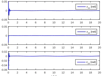
that the tracking performance of the robot is satisfactory. In
Fig. 2, tracking error
z
1is plotted, and it can be known that
z
1converges to a small neighborhood of zero with a satisfactory
overshoot. In Fig. 3, control input
µ
is given and is constrained
in the predefined region, i.e.,
µ
−ci≤
µ
i≤
µ
+ci,
i
= 1
,
2
,
3
, are
satisfied.
0 2 4 6 8 10 12 14 16 18 20
-1 0 1
xd1 [rad]
x11 [rad]
0 2 4 6 8 10 12 14 16 18 20
-1 0 1
xd2 [rad]
x12 [rad]
0 2 4 6 8 10 12 14 16 18 20
t [s] -1
0 1
xd3 [rad]
x
13 [rad]
Fig. 1. Actual trajectoryx1and reference trajectoryxdunder model-based
control (23).
0 2 4 6 8 10 12 14 16 18 20
-0.05 0 0.05
z
11 [rad]
0 2 4 6 8 10 12 14 16 18 20
-0.05 0 0.05
z12 [rad]
0 2 4 6 8 10 12 14 16 18 20
t [s] -0.06
-0.04 -0.02 0 0.02
z13 [rad]
Fig. 2. Tracking errorz1=x1−xdunder model-based control (23).
B. State-Feedback-Based Adaptive Neural Control Simulation
Implementation
In this section, the effectiveness of proposed control (30)
will be verified by simulation implementation. The number of
neural nodes is set as
l
= 2
12, the center of activation function
ψ
(
Z
)
is chosen in the area of
[
−
1
,
1]
×
[
−
1
,
1]
×
[
−
1
,
1]
×
[
−
1
,
1]
×
[
−
1
,
1]
×
[
−
1
,
1]
×
[
−
1
,
1]
×
[
−
1
,
1]
×
[
−
1
,
1]
×
[
−
1
,
1]
×
[
−
1
,
1]
×
[
−
1
,
1]
. The width of centers is set as
η
2= 1
. Initial
values are set as
θ
ˆ
1(0) = ˆ
θ
2(0) = ˆ
θ
3(0) = [0
, . . . ,
0]
T∈
R
212. The parameters of the updating law given in (32) are
set as
Γ
1= diag[100
,
100
,
100]
,
Γ
2= diag[50
,
50
,
50]
,
Γ
3=
diag[100
,
100
,
100]
and
ς
= 0
.
0001
. The rest of controller
parameters are the same as those of section IV-A.
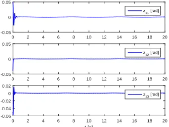
The detailed simulation results are given in Figs. 4-7. In
Fig. 4, actual trajectory
x
1and reference trajectory
x
dare
plotted, respectively, and Fig. 4 shows that
x
1converges to a
small neighborhood of reference trajectory
x
d, which shows
that the tracking performance of the robot is satisfactory. In
Fig. 5, tracking error
z
1is given. Fig. 6 plots control input
µ
and furthermore
µ
is constrained in the the predefined region,
i.e.,
µ
−ci≤
µ
i≤
µ
+ci,
i
= 1
,
2
,
3
, are satisfied. Fig. 7 gives the
Euclidean norm of weight vector
θ
ˆ
i,
i
= 1
,
2
,
3
. By observing
[image:7.612.60.287.300.417.2]0 2 4 6 8 10 12 14 16 18 20 -20
0 20
Input
µ
1
[Nm] µ
1
µ+c1
µ
-c1
0 2 4 6 8 10 12 14 16 18 20
-20 0 20
Input
µ
2
[Nm] µ
2
µ+
c2
µ-c2
0 2 4 6 8 10 12 14 16 18 20
t [s] -20
0 20
Input
µ3
[Nm] µ3
µ+
c3
[image:8.612.347.522.59.193.2]µ-c3
Fig. 3. Control inputµunder model-based control (23).
0 2 4 6 8 10 12 14 16 18 20
-1 0 1
xd1 [rad]
x11 [rad]
0 2 4 6 8 10 12 14 16 18 20
-1 0 1
xd2 [rad]
x
12 [rad]
0 2 4 6 8 10 12 14 16 18 20
t [s] -1
0 1
xd3 [rad]
[image:8.612.84.259.60.194.2]x13 [rad]
Fig. 4. Actual trajectoryx1and reference trajectoryxdunder
state-feedback-based adaptive neural control (30).
C. Output-Feedback-Based Adaptive Neural Control
Simula-tion ImplementaSimula-tion
In this section, the effectiveness of proposed control (43)
will be verified by simulation implementation. High-gain
ob-server parameters are set as
λ
1= 1
and
ρ
= 0
.
0007
. The rest
of controller parameters are the same as those of section IV-B.
The detailed simulation results are given in Figs. 8-11.
In Fig. 8, actual trajectory
x
1and reference trajectory
x
dare plotted, respectively, and Fig. 8 also illustrates that
x
1converges to a small neighborhood of reference trajectory
0 2 4 6 8 10 12 14 16 18 20
-0.05 0 0.05
z11 [rad]
0 2 4 6 8 10 12 14 16 18 20
-0.05 0 0.05
z12 [rad]
0 2 4 6 8 10 12 14 16 18 20
t [s] -0.06
-0.04 -0.02 0 0.02
z13 [rad]
Fig. 5. Tracking errorz1=x1−xdunder state-feedback-based adaptive
neural control (30).
0 2 4 6 8 10 12 14 16 18 20
-20 0 20
Input
µ
1
[Nm] µ
1
µ+c1
µ
-c1
0