Contents lists available atScienceDirect
Journal of Building Engineering
journal homepage:www.elsevier.com/locate/jobe
Design optimisation using convex programming: Towards waste-efficient
building designs
Muhammad Bilal
a,⁎, Lukumon O. Oyedele
a,⁎, Olugbenga O. Akinade
a,
Juan Manuel Davila Delgado
a, Lukman A. Akanbi
a, Anuoluwapo O. Ajayi
a,
Muhammad S. Younis
baBig Data Analytics and Artificial Intelligence Lab (BDAL), Bristol Business School University of West of the England, Frenchay Campus, Coldharbour Lane, Bristol, United Kingdom
bSchool of Electrical Engineering & Computer Science (SEECS), National University of Sciences & Technology (NUST), Islamabad, Pakistan
A R T I C L E I N F O
Keywords:
Space layout planning Convex programming
Design for dimensional coordination Waste reduction
Floor layout optimisation
A B S T R A C T
A non-modular building layout is amongst the leading sources of offcut waste, resulting from a substantial amount of onsite cutting and fitting of bricks, blocks, plasterboard, and tiles. The field of design for dimensional coordination is concerned with finding an optimal configuration for non-overlapping spaces in the layout to reduce materials waste. In this article, we propose a convex optimisation-based algorithm for finding alternative floor layouts to enforce the design for dimensional coordination. At the crux of the proposed algorithm lies two mathematical models. The first is the convex relaxation model that establishes the topology of spaces within the layout through relative positioning constraints. We employed acyclic graphs to generate a minimal set of relative positioning constraints to model the problem. The second model optimises the geometry of spaces based on the modular size. The algorithm exploits aspect ratio constraints to restrict the generation of alternate layouts with huge variations. The algorithm is implemented in theBIMWastetool for automating the design exploration
process.BIMWasteis capable of investigating the degree to which designers consider dimensional coordination.
We tested the algorithm over 10 completed building projects to report its suitability and accuracy. The algorithm generates competitive floor layouts for the same client intent that are likely to be tidier and more modular. More importantly, those floor layouts have improved waste performance (i.e.,8.75%less waste) due to a reduced tendency for material cutting and fitting. This study, for the first time, used convex programming for the design optimisation with a focus to reduce construction waste.
1. Introduction
Construction waste is a grave environmental concern. Construction firms incur substantial costs yearly for managing construction waste, and this trend keeps rising due to escalating construction activities worldwide [32,3,13]. At the moment, waste management practices focus on managing waste after it occurs. These practices lack proactive waste reduction strategies, which would have improved the sustain-ability and profitsustain-ability performance of firms. This insustain-ability has been the main reason for their ineffectiveness so far[23,30,11]. This rea-lisation has led to a paradigm shift in the waste management research. Majority of researchers prefer preventive measures over curative stra-tegies through planning at early design stage[38,10,23]. This new vista of waste management is often referred to as designing out waste. From an analytics perspective, designing out waste is more of a predictive or
even prescriptive than the legacy descriptive analytics. Most popular BIM-authoring software lack provisions for enforcing designing out waste activities. There are many circumstances where designers take decisions, like designing spaces, specifying materials, designing doors and windows, etc. These design choices seem trivial; however, they influence the waste generation potential of BIM designs[25,13,39].
Design for dimensional coordination is an important consideration to reduce construction waste through proactive planning at the design stage. The well-coordinated and modular layouts are reported to have improved the waste performance of designs[2,20,24,31]. In design for dimensional coordination, attempts are made to correlate building layout with materials and elements used during construction to avoid conflicts during the actual construction process. This topic is extensive and cannot be covered in a single study. In this paper, the scope is restricted exclusively to floor layout optimisation for waste
https://doi.org/10.1016/j.jobe.2019.01.022
Received 25 September 2018; Received in revised form 14 January 2019; Accepted 14 January 2019 ⁎Corresponding authors.
E-mail addresses:[email protected](M. Bilal),[email protected](L.O. Oyedele).
Available online 22 January 2019
2352-7102/ © 2019 The Authors. Published by Elsevier Ltd. This is an open access article under the CC BY license (http://creativecommons.org/licenses/BY/4.0/).
minimisation, where spatial units (SUs) in the layout are checked for their compliance with the modular size or dimensions of construction materials. The idea is to increase the modularity of SUs for avoiding material cutting and fitting as most building components are manu-factured according to the standard module [20]. This aspect of di-mensional coordination resembles a class of optimisation problems known asSpace Layout Planning (SLP).
TheSLPis concerned with finding the best configuration of SUs in the floor layout to achieve the intended design goals[26]. The possible SUs in the floor layout considered in this study are usually functional/ living spaces, lobbies and corridors. The design goals vary from task to task. In this study, the coordination of SUs is subject to achieving modular designs. Well-coordinated design require fewer efforts during assembly due to reduced material cutting and fitting. Such designs produce relatively less amounts of offcut waste. The SLP is highly combinatorial due to infinite ways of organising SUs in the floorplan [12]. From a designer's perspective, manually exploring all configura-tions of SUs for waste reduction are impractical due to time and efforts required for the task. A computational tool is desirable for assisting designers to automatically carry out SLPtasks and produce designs with lesser waste output.
This paper showcases the practicality of design for dimensional coordination through SLP. Thus, the overarching aim of this study is to propose a convex programming algorithm for SLP where SUs are opti-mised in the floor layout of a building design based on standard module or material dimensions. This coordination will reduce the need for material cutting and fitting onsite, eventually lowering offcut waste. The specific objects of the research include:
1. To devise convex programming algorithm for floor layout co-ordination to minimise construction waste
2. To implement algorithm in BIMWaste tool for demonstrating its suitability in design exploration
This study carried out experimental research to achieve the stated research objectives. It begins with a review of existing literature about designing out waste and requirements of using SLPin dimensional coordination. Afterwards, we proposed an algorithm for SLP-based floor layout optimisation. Convex programming is chosen for problem formulation that is a subfield of optimisation where final solution is assured to be the optimal solution[6]. The proposed algorithm com-prised of two kinds of mathematical expressions. The first is the convex relaxation formulation that establishes the topology of SUs within the floor layout through relative positioning constraints. We employed acyclic graphs to generate a minimal set of relative positioning con-straints; hence improved the overall algorithmic performance. The second formulation optimises the geometry of spaces to yield optimal floor layouts. The framework is bounded by aspect ratio constraints to restrict the generation of layouts with extreme variations or the ones with overly long and narrow spaces. Finally, the algorithm is im-plemented in theBIMWastetool and evaluated by exploring several building designs.BIMWasteis found useful by designers to quickly get the feedback on design variations and engage in waste reduction through dimensional coordination.
Organisation of paper:The paper begins with a literature review on designing out construction waste and the need for coordination through convex programming. Then, the research methodology of this inquiry is described inSection 3. After that, the algorithm design for the floorplan optimisation is presented inSection 4. The BIM integration challenges experienced during algorithm implementation inRevit SDK are explained inSection 5. The results and validation of the algorithm are given inSection 6. Discussions and implications for practice are specified inSection 7. Finally, the conclusion, limitations, and future research directions are given inSection 8.
2. Literature review
2.1. Designing out construction waste
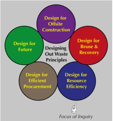
One-third of construction waste is attributed to decisions under-taken at early design stage and can be avoided through proactive planning for waste reduction[23,2]. Designing out construction waste emphasises on waste prevention through early engagement of stake-holders[38]. Five design principles shall be regarded for designing out waste[20]. These include 1) design for re-use and recovery 2) design for resource efficiency 3) design for off-site construction, 4) design for resource-efficient procurement, and 5) design for the future. This study explores opportunities laid out by design for resource efficiency (see Fig. 1) where plants, materials, people, etc. are worked out to ensure waste reduction during the construction stage. To this end, several strategies are affirmed to reduce waste, including site topography planning[4], materials specification and detailing designs[28], struc-tural and planning grid coordination[20], and supplier & procurement optimisation [19]. Particularly, dimensional coordination [18] is amongst integral strategies for achieving resource efficiency. Well-co-ordinated designs avoid unnecessary material cutting and fitting onsite which lead to reduced offcut waste[4]. Additionally, less coordinated designsmostly result in cost and time overrun. A discrepancy of up to 10 mm in the dimensions of design is revealed to cause a rework of more than £ 3000[37].
[image:2.595.324.541.57.289.2]Floor layouts comprise a major aspect of design and bear relation-ship to the offcut generation with respect to different types and sizes of construction materials used during the construction process[10,20]. At the moment, no BIM tool facilitate designers in relating floor layouts with construction materials to achieve dimensional coordination. The automation of dimensional coordination of floor layouts with materials is vital to promote pre-emptive measures in waste reduction. There is a clear need for automating such tasks to design out waste. The en-gagement of designers at the early design is paramount. But, the issue of design exploration is computationally expensive due to unlimited configurations for floor layouts. A major limitation of existing solutions lies in their response time. An instantfeedback about waste output is required for designers to see the implications of changes on waste output of the design. Moreover, the solution shall be integrated with
native BIM authoring tools. Otherwise, the wider adoption of digital innovation would be hard to prevail in the industry.
2.2. Space Layout Planning (SLP)
The optimisation of spatial units (SUs) regarding their sizes and placement in the floor layout falls under the space layout planning (SLP) problems. This topic is studied in the literature by several au-thors. SLP algorithms fall into two categories, i.e., auto-SLP and semi-auto SLP algorithms. Regardless of their grouping, SLP algorithms aim to facilitate designers in conceptual design process to generate optimal configurations of sizes and placement for SUs in floor layout. Auto-SLP algorithms do not require initial design of a facility to begin with and produce layouts with minimal user intervention. Shaviv & Gali[35] carried out an extensive literature survey on this topic. Most auto-SLP algorithms explore all configurations in the floor layout[14], which is infeasible due to an exploration of the entire search space of arranging and sizing the SUs. Several authors employed methods like greedy searching to partition solution space and reduce computational com-plexity in these systems[35]. Michalek et al.[27]applied evolutionary optimisation to search room connectivity for generating alternate floor layouts. However, the suggested configurations are not always tidier and need further refinements by designers. Harada et al. [17]used shape grammar in SUs generation to interactively manipulate layouts. Most auto-SLP algorithms tend to be complex. Their applications are mainly focused on architectural layouts of commercial or public sector buildings.
To avoid inherent complexities of auto-SLP algorithms, several re-searchers proposed semi-auto algorithms for locally coordinating the floor layouts. These algorithms optimise SUs manually created by ar-chitects. An extensive literature review on semi-auto SLP algorithms is provided in Liggett [22]. Schwarz et al.[34]proposed technique that accepts the rough arrangement of a layout as an input and generates a numerically optimised plan. A major shortcoming of such algorithms is slower response time due to non-convexity of underlying objective function and modelling constraints. Arvin & House[5]utilised physical design attributes in modelling, but their approach was sensitive to initial layout conditions. Convex programming is a useful alternative for finding globally optimal solutions with better response time. Most authors pro-posed techniques for tackling use cases like building façade generation [29], structural feasibility analysis[40], architectural textures designing [21], generating building exteriors[7], architectural surfacing[33], and 3D design extrusion[41]. However, none of these works can be tailored for achieving high-level specifications like energy consumption and waste minimisation. Specifically, none of existing tools provides opti-misation of floor layouts based on material dimensions which can not only reduce assembly efforts but also prevent offcut waste.
3. Research methodology
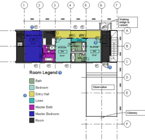
In this section, research methodology to achieve the stated research objectives is explained. After a review of existing literature, an objec-tive methodology is adopted for proposing the algorithm for design optimisation using convex programming. When a study employs the objective methodology for discovering realities, it grounds into positi-vists worldview[8,16]. Similar types of design exploration problems often demand a systematic approach to capture the underlying domain during such formulations[15]. The study, therefore, used objectivist epistemology as design properties are exploited for judging realities through constraint programming[9]. To this end, mathematical mod-elling is used with the case study design. The algorithm is conceived to capture domain interactions for modelling design for dimensional co-ordination. A case study of a residential building with a gross floor area GFA of 22,900 m2 is considered during problem formulation. The floorplan of level 1 used in modelling is shown inFig. 2. Various tun-ning strategies were employed to ensure algorithmic accuracy and
performance. We implemented the algorithm in BIMWaste system whereGurobiis used as the numerical solver. The proposed algorithm is evaluated with 10 hand picked building projects. For comparison purposes, only completed projects were considered. Our analysis re-vealed that architects often ignore standardisation and dimensional coordination. Majority of spatial units in designs were not correlated with either modular sizes or construction materials. This non-standar-disation not only makes floorplan look untidy but also generates offcut waste due to material cutting and fitting onsite.
To facilitate design for dimensional coordination, designers shall utilise an automated solution to see how their design variations influ-ence the generation of construction waste. This is because timely feedback is crucial for letting architects understand various interactions between design strategies and waste output. Existing propositions in the form of design guides andchecklist do not provide practical solutions for waste reduction[31,32,10]. This has led to an integration of the proposed algorithm into BIM-authoring tool. The solution was intended to respond quickly and give suggestions with minimal user interven-tion. Thisintegration was achieved to reduce errors which mostly occur when manual inputs were involved. Since faster response time is a vital feature for engaging designers in the design exploration process, the choice of convex programming was opted in this research. While real-world problems are hard to conceive as convex programs, these pro-grams (if modelled accurately) can run faster than other non-linear algorithms. This research used the floorplanning approach where spa-tial units are optimised for their sizes and placement in an outer boundary of fixed size. The final solution reads building design, and then seamlessly process floor layouts one at a time. By exploiting SDK features, the system extracts all information from BIM models to invoke the optimisation model. These data are passed to Gurobi process which solves the system of equations and returns the final solution. This final solution is passed to the waste estimation module in the BIM-Wastesystem which computes the waste output of the revised design. Designers can either use or discard those insights for design optimisa-tion, and accordingly plan for waste reduction strategies at the early design stage.
4. Proposed convex programming algorithm
[image:3.595.310.553.55.288.2]The main contribution of this work is the proposed convex pro-gramming algorithm for design for dimensional coordination. Our
formulation considered floor layouts with rectangular spaces which are informed by the fact that the geometry of most building spaces are predominantly rectangular[36]. One argument for this rectangularity of floor layouts lies in the constraints of packaging the spatial units closer together. This packaging allows superior flexibility for dimen-sional coordination that leads to the higher performance of floor lay-outs. Our analysis of floor layouts of 200 residential buildings also confirmed this fact where89%of spaces were found rectangular (square and triangle) whereas the rest were non-orthogonal and curvilinear. The following subsections explain the semantics and functionality of the proposed convex optimisation algorithm for design exploration. To this end, we first described proposed notations used in the formulation. Then, we explained critical capabilities of the proposed convex model. And finally, decision variables, constraints, and the objective function of the proposed formulation are provided.
4.1. Proposed notations
We modelled design for dimensional coordination problem as floorplanning problem, in which rectangles are used to represent spatial units. The floor layout of building is conceived as a union of non-overlapping spatial units ( i i). In the proposed algorithm, we la-belled as rank-1 tensor of spaces iwhereibegins at 1 and goes up to nspaces in the floor layout. The location of iis expressed by a pair of valuesxs i andysi, representing its lower left corner. The size of a spatial unit iis denoted by the width (wsi) and the height (hsi). The width and height of external parcel of floor layout is denoted by and , respectively. In this way, geometry and position of i, comprising the floor layout, are modelled. The optimisation algorithm is intended to find the best size and position of i within the fixed building parcel. For the sake of waste reduction, sizes shall be multiple of either standard module or construction materials.Fig. 3shows pro-posed notations used in formulation pictorially where the floor layout is captured as vector of cells where cells are 4-tuple of form (wsi,hsi, xsi, andysi).
4.2. Objective function
In the proposed formulation, the objective is to assure that spaces of the floor layout are multiple of the modular size, or at worst, non-modularity is factored out to fewer spaces rather than scattered all over the design. Modular designs tend to reduce material cutting and fitting, and hence produce less waste during the construction process. Based on
this intuition, the objective function was initially set as shown in Eq. (1).
= =
min (O ) ( )O
i n
spi i
n
si
1 1 (1)
whereOspiandOsidenote the amount of offcuts produced by each i in the original floor layout and the optimised floor layout. The algo-rithm finds a configuration that minimises offcut waste by making minor adjustments to the layout. To calculate offcuts, the above for-mulation was required to employ non-linear functions such asceiland modulusas part of executing expressions shown in Eqs.(2)–(7). These functions made the formulation non-convex, which was undesirable due to computation complexity and higher response time.
= =
Os (ceil n( ) n)
i N
i i
1 (2)
= + ×
+
=
n w t imodulus
m t
( ( 2)
t i
n l
l
1
c
(3)
= +
n w
m t
e l
l (4)
= +
+
n w t
m t
o l
l (5)
= × + ×
wl (ml ne) (t ( ))ne (6)
= × + ×
wl (ml no) (t (no 1)) (7)
whereml,mw,mhrepresent the length, width, and height of mod-ular size or construction materials (e.g., brick), tis the mortar joint thickness,wl,ww,whdenotes the length, width, and height of the
ele-ment e,bis the bond type (i.e. half-running stretcher, one-third running stretcher),no,neare materials needed to build odd and even courses,nt is the total materials,Ois the offcuts, andncthe total number of vertical courses.
To avoid non-convex formulation, the optimisation logic is slightly altered for generating modular layouts with minor changes to the in-itially proposed design. The objective function is henceforth set to minimise the difference of sizes of i proposed by the algorithm and original size of i, as illustrated in Eq.(8). The algorithm optimises sizes of i in the floor layout by keeping in view the aspect ratios and in-tegerality constraints which isolate non-modularity in spaces as trailing ‘unassigned’ space between i. This non-modularity usually arise from non-modular dimensions of and . The algorithm merges these trailing spaces into a minimum number of ito intact symmetry of the layout.
× ×
= =
min (ws hs ) (ws hs)
i n
pi pi i
n
i i
1 1 (8)
The variableswspi andhspi in Eq.(8)denote originally proposed
width and height of theithspatial unit, respectively whilews
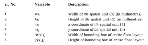
[image:4.595.308.551.205.359.2]iandhsiare the optimisation variables.Table 1provides explanation of decision variables used in this formulation.
[image:4.595.56.271.533.727.2] [image:4.595.305.559.666.743.2]Fig. 3.Proposed notations used in floor layout optimisation.
Table 1
Notations used in the design optimisation.
Sr. No. Variable Description
1 wsi Width ofithspatial unit (S) (in millimetres) 2 hsi Height ofithspatial unit (S) (in millimetres) 3 xsi xcoordinate ofithspatial unit (S) 4 ysi ycoordinate ofithspatial unit (S)
5 Width of bounding box of entire floor layout
4.3. Constraints specification
In this section, we explain various types of constraints used in the formulation. Floorplanning optimisation mainly influenced the choices of our constraint specification. The topology and geometry of floor layouts are captured through these constraints. In subsequent sections, we discuss design requirements briefly, followed by constraints for-mulation and some adjustments to optimise the algorithm.
4.3.1. Bounding box constraints
In the proposed formulation, a configuration ( ) is only considered valid if all spaces ( i) in the configuration fall within the external en-velope or bounding box of the design. The following set of linear equalities are used to enforce this requirement in the formulation (see Eq.(9)).
+ +
xsi 0, ysi 0, xsi wsi , ysi hsi (9)
4.3.2. Non-overlapping constraints
Spatial units in the layout shall not overlap other spaces except on their boundaries. Any valid configuration shall avoid each pair of dis-joint spaces from occupying the same location. To avoid i from in-tersecting j, the following constraints, as shown in Eq.(10), are added to the algorithm.
=
int( i j) for i j (10)
These constraints shall be specified for each pair of i and j that are on the right, left, top or bottom of each other. Some new inequal-ities, as shown in Eq.(11), are needed to ensure sidedness of i con-cerning j.
+ +
+ +
xs ws xs xs ws xs
ys hs ys ys hs ys
, ,
, ,
i i j j j i
i i j j j i (11)
The combinatorial nature of inequalities in Eq.(11)requires these constraints shall be applied before the non-overlapping constraint shown in Eq.(10).
4.3.3. Topology constraints
We added some non-equalities to preserve topology of the design using relative positioning constraints. Relative positioning constraints capture one of four positions (i.e., left, right, above, and below) for each in the layout. Eq.(9)can be tailored to achieve such functionality; however, there are other efficient ways to implement these constraints. A simple approach used in this formulation is to generate two relations describingleftof, and meaningbelowfor a layout. These re-lations facilitate the generation of constraints like iis to the left of jif
i j
( , ) , and i is below j, if( , )i j . The general form of
in-equalities, generated by these relations, is shown by Eq.(12). To vali-date the accuracy of and , we further need for each entry( , )i j where i j, one of the following shall hold: ( , )i j , ( , )j i ,
i j
( , ) ,( , )j i , and that( , )i j ,( , )i j . These relations have
several notable characteristics that are used to generate these in-equalities. Particularly, these relations are anti-asymmetric and transi-tive. Anti-symmetry means that if( , )i j then( , )i j also holds. Similarly, transitivity says if( , )i j and( , )j k , then( , )i k must also be true. Merely translating these relations into relative po-sitioning inequalities using greedy techniques is likely to end up gen-erating many redundant inequalities. For example, if we impose in-equalities for ( , )i j and ( , )j k , then there is no need for checking( , )i k due to transitivity of .
+ +
xs ws xs for i j
ys hs ys for i j
, ( , )
, ( , )
i i j
i i i (12)
To circumvent the above problem, two acyclic graphs (for hor-izontal) and (for vertical), each comprising nodes, are generated instead of relations and . Graph generates the relation for each entry( , )i j if a path exists betweeniandjin . The graph creates the relation similarly. This approach decreases4N inequal-ities while generating the relative positioning constraints. This is be-cause we impose constraints for graphs and and the rest follows from transitivity. The following set of linear inequalities is generated accordingly (see Eq.(13)).
+ +
xs ws xs for i j
ys hs ys for i j
, ( , )
, ( , )
i i j
i i i (13)
These acyclic graphs are also found useful to generate a minimal set of inequalities. The non-zero constraintxi 0is only relevant on the leftmost spaces, whereas, the inequalitiesxi+wi only need to be
specified for the right-most spaces. Overall, a large number of re-dundant inequalities are pruned using this approach and just the minimal set of bounding box inequalities, as shown in Eq.(14), needed to be applied.
+ +
xs for minimal i ys for minimal i xs ws for minimal i ys hs for minimal i
0 ,
0 i
i
i i
i i (14)
The general form of generating the minimal set of the bounding box constraints (Eq.(9)) and relative positioning constraints (Eq.(11)) for the horizontal acyclic graph for the ground floor layout are illustrated inFig. 4.
+ + + + + + + + + +
xs xs ws xs ws xs
xs xs ws xs ws xs
xs xs ws xs ws xs
xs xs ws xs
xs ws xs
xs ws xs
xs ws xs
0 0 0 0
1 2 2 6 6 5
6 3 3 5 5 4
7 4 4 5 5 3
8 7 7 9
8 8 9
9 9 2
1 1 2 (15)
The similar strategy is used for generating relative positioning constraints for the vertical graph as well, for the building design shown inFig. 2.
+ + + + + + + + + + +
ys ys hs ys hs ys
ys ys hs ys hs ys
ys hs ys hs ys
ys hs ys
ys hs ys
ys hs ys
ys hs ys
ys hs ys
0 0
1 4 4 1 1 8
2 5 5 1 1 9
6 6 8 8 7
9 9 6
7 7 6
2 2 5
2 2 3
3 3 4 (16)
4.3.4. Aspect ratio constraint
Aspect ratio constraints are specified to impose the upper and lower bounds on sizes of the spatial units. The objective is to keep the design aesthetics intact and prevent the generation of configurations with huge variations. Eq.(17)shows expressions to compute aspect ratio bounds for the layout. These expressions produce limits that are used by the optimisation algorithm to impose some non-linear inequalities of the following form:
asmin hs wsi/ i asmax (17)
whereasmin and asmax are the dimensions of modular sizes that
4.3.5. Integerality constraint
The decision variables likews hs xs, , ,andysare declared integers to avoid taking configuration involving fractional numbers. This specifi-cation has narrowed the search space with only integer solutions. The following integerality constraints helped the algorithm achieve this requirement.
xs integer; ys integer; ws integer; hs integer; (18)
4.4. Algorithm Implementation in Gurobi Solver
We implemented the algorithm using Gurobi solver, which is capable to handle different types of optimisation workloads [1]. Gurobiis widely used for industrial automation in fields like produc-tion, distribuproduc-tion, purchasing, finance, capital investment and human resources.Gurobican scale up to problems involving millions of de-cision variables. Gurobi can solve linear, quadratic, mixed-integer linear,quadratically constrained,mixed-integer quadratic, and mixed-integer quadratically constrained programs.Gurobican be interfaced through different languages like C, C#, Java, and Python for developing software. We usedGurobiwith . Net interface for integration withRevit SDK.
The optimisation model for the proposed algorithm is created using GRBModel() class, where decision variables are instantiated with GRBVar() object and added to the model by invoking addVar()
method. The quadratic expressions of the objective function are con-structed byGRBQuadExpr()class object which is attached to model using setObjective() method of the model class. Finally, con-straints are specified in the model usingGRBLinExpr()class objects. Listing 1illustrates the code implementation of the proposed algorithm. Listing 1.Gurobi Implementation of the Algorithm
5. BIM integration challenges
5.1. Bounding box of floor layout using convex hull
The first challenge encountered was to automatically get the width and height of the bounding box of the floor layout. At the moment, Revit SDKdoes not offer built-in methods to get this information from BIM directly. Several approaches were sought to retrieve this in-formation. Firstly,IExportContextclass provided by theSDKwas used for obtaining the coordinates of visible components in the design which were used to calculate dimensions of the floor layout. This ap-proach seemed subtle at first; however, the response time of program grew exponentially as larger models were explored during the testing and validation phase. Another method was checked to achieve this feature where building elements were iterated for each floor, and the bounding box was expanded as the loop continued. This approach also did not work well. Lastly, a solution that computed the convex hull of floor layout using FilteredElementCollector class worked in
obtaining width and length of the bounding box. This approach had higher accuracy and performance than other proposals.
[image:7.595.120.478.55.202.2]There were still some notable limitations. Firstly, this approach does not consider linked models. In linked models, FilteredElementCollectorclass return geometry of the source models which has to convert to the geometry in host models. Besides, FilteredElementCollectorclass returns all elements in the de-sign when view-specific details of the bounding box shall suffice. We can augment the performance of FilteredElementCollector with theActiveViewoption to limit the search space to a section or 3D view. For now,FilteredElementCollectorclass was found reliable in results and faster in response time. Other possible ap-proaches like CustomExporter class can be reliable to FilteredElementCollector as the class is designed to iterate over visible geometry in the view only mode.
Fig. 4.An example and graphs are shown to explain the logic for generating relative positioning constraints. If a path exists fromitojin , theniis to the left ofj. If a path exists fromitojin , theniis belowj. Graph on left side shows these constraints for the design layout at the right side.
[image:7.595.120.480.245.534.2]5.1.1. Coordinates of spatial units in floor layout
Another automation challenge was to getx andycoordinates of spatial units in the floor layout. We used architectural room object in-stead of the structural space object. Therefore, our approach is limited to work with BIM models where designers annotate rooms as archi-tectural objects. Several options were tried to obtain this information from the design. The first idea was to get coordinates of spatial units using room location points; however, it was found that location points were of no use, whatsoever. Instead, room boundary object provided the way forward. We retrieved room boundaries, iterated over the curves, and determined the lower left endpoints. This approach only considers rooms with rectangular walls and become inaccurate if boundaries are curved.
Another approach for fetching coordinates of spaces in the floor layout was also tested. The approach worked as follows. The compu-tation begun with getting all architectural rooms from the floor layout and then getting curves for each room through their boundary seg-ments. And then, the starting and ending points of all the walls of a room were retrieved. De-duplication was performed to ignore the du-plicate points. These points were finally sorted in ascending order by coordinates using a custom sort algorithm. The coordinates of the lower left corner were taken by returning points at the top of the list.
5.2. Width and height of spatial units in floor layout
Another challenge in BIM integration was to seamlessly retrieve the width and height of spatial units in the floor layout.Revit SDK pro-vides built-in functions to get sizes of all objects using built-inlength method on the Curve class. However, there were no provisions for calculating the directions of walls which was crucial for computing the width and height of spaces in the layout. As a result, the default func-tionality was not of much usefulness in this automation.
The first task in this activity was to annotate the walls with the directions they are facing. The width of a spatial unit is the length of walls facing the north or south direction, whereas its height is the length of walls facing east or west. We then wrote custom functions to retrieve this information based on the following intuition. The y-axis of walls facing the north or south always remains unchanged; whereas, the x-axis of walls facing east or west is same. Once the walls are annotated, and their directions are determined, the function invokes thelength built-in method on theCurveclass to get this information for all spatial units.
5.3. Acyclic graphs for topology modelling
The last challenge in BIM integration was the formation of ad-jacency matrices of spatial units to capture the topology of the floor layout. This information is required to generate relative positioning and other constraints automatically before invoking the Gurobi solver.
Custom code was developed to create two matrices ( and ) for this purpose. The rows in matrix captures the fact whether a spatial unit is on the right or the left side of another spatial unit. If the value is 1 then the spatial unit is at the right side otherwise the left side. An ex-ample matrix is illustrated inEq. (19)to explain the proposed ap-proach.
=
0 0 0 0 0 1 0 0 0 0 0 0 0 0 1 0 0 0 0 1
1 0 0 0 0 (19)
Likewise, the graph is to capture whether the spatial units fall on the top or bottom of other spatial units. The code used for labelling spatial units in the previous subsection was handy to generate these matrices. TheRevit SDKdoes not offer built-in routines to extract such information.
6. Validation of proposed algorithm
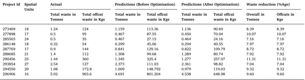
We validated the proposed algorithm over 10 residential projects of varying floor layouts, comprising an average of 20 spatial units. This data is obtained from a leading construction firm. The construction activities in the majority of these projects were almost completed. The company usedreconomydatabase to store the waste disposal records of these projects. A record in the reconomy database contains the details of each waste disposal record including site, date, container size and type, movement type, waste type, EWC code, and the amounts of waste collected in tonnes.Table 2shows the summary of actual con-struction waste generated by these projects. Overall, these projects have produced approximately 15 tonnes of construction waste. Out of which, the proportion of waste generated by offcuts was14%that weighed to
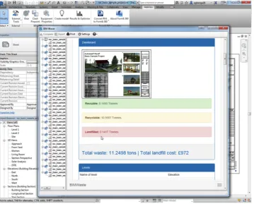
2.12 tonnes. An initial projection of construction waste produced by these projects was also obtained from theBIMWaste tool to validate the accuracy of its waste estimation subsystem. The BIMWasteuses advanced deep learning models for predicting construction waste of the design. This study does not cover the waste estimation models used in the system. The overall waste prediction accuracy reported by BIM-Wastefor these projects was93.47%. The BIMWastesystem reads a large number of design features to make these predictions.
[image:8.595.39.559.608.745.2]In most cases, theBIMWastepredictions were pretty close to actual waste generated by these projects. In some cases, these waste projec-tions were slightly less than what was produced during the actual construction process. We investigated these projects and also found several standardisation and dimensional coordination issues. Notably, the dimensions of spaces in these BIM models were not reconciled with the specified construction materials. Afterwards, the floor plans of these BIM models were optimised through the proposed design exploration algorithm. Once these designs were dimensionally correlated, BIMWastewas used again to predict the waste output of these models. Table 2
Construction Waste Statistics (Actuals, Predicted, and Optimised). Project Id Spatial
Units Actual Predictions (Before Optimisation) Predictions (After Optimisation) Waste reduction (%Age)
Total waste in
Tonnes Total offcutwaste in Kgs Total waste inTonnes Total offcutwaste in Kgs Total waste inTonnes Total offcutwaste in Kgs Overall inTonnes Offcuts inKgs
273409 18 1.24 124 1.159 113.36 1.136 90.69 8.39 8.39
277898 17 0.5 95 0.467 87.55 0.450 70.04 10.07 10.07
285503 24 0.5 35 0.467 27.15 0.464 24.16 7.16 7.16
286148 18 0.32 54 0.299 45.06 0.294 40.55 7.97 7.97
287769 17 0.9 144 0.841 129.16 0.822 109.79 8.72 8.72
288685 21 1.4 112 1.308 99.68 1.289 80.74 7.92 7.92
290456 25 1.44 360 1.345 325.4 1.277 257.07 11.31 11.31
293854 27 2.54 127 2.373 111.03 2.361 98.82 7.04 7.04
294550 20 1.08 172.8 1.009 148.792 0.979 119.03 9.32 9.32
The proposed algorithm was able to reduce an average of 8.75% of construction waste, produced through material cutting and fitting on-site. This reduction accounts for 587 kg of offcuts waste which is a reasonable improvement by making slight changes to the floor layout. The architects also commended the response time of the system. BIMWaste was able to re-execute waste estimation models instantly with every significant design change to assess whether the waste output of the design has increased or decreased as a result of recent design changes. The system has enabled the early engagement of architects in waste reduction process which was one of the fundamental aspirations of this study.
7. Discussions
The proposed algorithm produced the floor layouts with the fol-lowing characteristics. Firstly, the algorithm always generates spatial units that are multiples of either modular sizes or dimensions of con-struction materials. Secondly, instead of changing floor layout entirely, the algorithm optimises dimensions of spaces with minor alterations to the design to intact the aesthetics of original design as much as possible. Further, the non-modularity of spatial units is pushed to fewer spaces at one side of the layout. Also, the algorithm does not yield geometry or placement of spaces that exceed external parcel of the floor plan and therefore retains symmetry of the design for spatial units in the row or column. Finally, the architects can see the feedback from algorithm instantly to look at their implications for waste output without much waiting time. They can perform more adjustments to the design or re-vert changes if the waste output is projected to increase.
There have always been divided opinions about the practicality and effectiveness of various waste reduction strategies between academics and the industry. While literature bolsters the importance of designing out construction waste as an ideal strategy where a huge difference can be made with fewer efforts of design variations[2,24], the practitioners on the other hand like architects do not acknowledge argument of de-signing out waste. It is absurd for designers to relate design decisions to the waste output of their models. Existing research in designing out waste at large emphasises on producing design guides and checklists for informing designers on waste reduction through design[30,31]. These guidelines are far from being practical as designers generally cannot see the value of investing time in planning for waste reduction at design stages [4]. They are either overly passionate about the aesthetics of their designs or rush to meet tight deadlines set out by their clients. The sub-contractors also do not care much about waste generation as they usually bill their clients for excessive materials as well as the generated waste. For these reasons, the waste generation is at rife in the industry. This study was a step forward for enabling early stakeholders’ en-gagement in waste reduction. To this end, a computational tool is de-vised for stakeholders to firstly see the implications of their design choices for the waste output of designs. Secondly, they are equipped to take actions based on the predictions provided by the tool to adjust the design such that it will eventually reduce the waste output. The results of validating the proposed algorithm for optimising the floor layouts of ten residential buildings were auspicious. This study is also in line with various initiatives worldwide which are keen on transforming con-struction processes using digital technologies. Only with such digital innovations, the industry will be able to deliver buildings 50% faster, 33% cheaper and with half the lifetime carbon emissions and waste generation as envisioned by UK Industry Strategy, 2018.
8. Conclusions
The issue of construction waste needs to be considered at the early design stage through proactive planning for waste reduction. We can reduce a significant proportion of waste by coordinating various aspects of the design. Particularly, dimensional coordination of floor layouts with material sizes or at least the standard module can reduce material
cutting and fitting onsite. Dimensional coordination is revealed to have enormous implication for waste output, and well-coordinated designs are likely to generate relatively less waste. This study illustrates this idea by proposing a convex programming-based algorithm that is im-plemented into theBIMWastesystem for helping designers to practice design coordination for reducing construction waste.
To this end, the problem of design coordination is formulated as the floorplanning problem. The proposed algorithm works as follows. It first models the topology of spaces in floor layout through convex re-laxation expressions which exploit relative positioning constraints in design modelling. Then, it optimises the sizes and placement of spatial units in the floor layout using the convex programming. The compu-tational complexity of algorithm was directly proportional to the number of spaces in a floor layout which was considered to influence response time of solution and thereby hinder adoption by architects. To tackle this issue, the algorithm employed acyclic graphs for constraints generation which has reduced the overall constraints needed for design exploration by4N whereNdenotes the number of spaces in the floor layout. The proposed formulation optimises rectangular spaces since the majority of spatial units in buildings were found to be rectangular-shaped. Only11% of designs in a massive corpus (i.e., 200 building designs) of a leading construction contractor were found non-rectan-gular and curvilinear. The choice of convex programming over other non-convex approaches like simulated annealing was preferred due to guarantee for the final answer to be the best solution. Besides, convex algorithms undertake lesser computation overhead than other coun-terparts during production deployment.
The proposed algorithm is implemented in theBIMWaste system which provides the designers with a comprehensive environment to plan for waste reduction during the early design stages.BIMWastehas reliable waste estimation functionality which was extended towards automatically suggesting alternate floor layouts for a given design with an objective to reduce waste. The tool suggests layouts which are tidier and more coordinated than the original floor layout suggested by the architects. We employedGurobisolver for solving the entire system of equations. The successful execution of the algorithm inGurobi re-vealed that the proposed formulation (i.e. objective function and con-straints) is convex. During the BIM integration, several challenges were tackled asRevit SDKdid not offer built-in capabilities to extract in-formation as expected by the algorithm. Finally, the proposed algo-rithm was validated for reliability by exploring BIM models of 10 construction projects of varying complexities. The algorithm suggested alternate floor layouts which reduced the waste output of these models by8.75%. In future studies, the capabilities of theBIMWastesystem will be improved to enable waste-efficient design detailing where the tool will suggest fewer materials used during construction by optimising pathways for certain types of materials like cables and plumbing pipes. Acknowledgment
The authors would like to express their sincere gratitude to Innovate UK (Grant application no. 54832-413479 and File No 102473) and EPSRC (Grant Ref: EP/N509012/1) for providing the financial support for this study.
References
[1] Gurobi optimization – a state of the art mathematical programming solver (2017). [2] S.O. Ajayi, L.O. Oyedele, M. Bilal, O.O. Akinade, H.A. Alaka, H.A. Owolabi,
K.O. Kadiri, Waste effectiveness of the construction industry: understanding the impediments and requisites for improvements, Resour. Conserv. Recycl. 102 (2015) 101–112.
[3] S.O. Ajayi, L.O. Oyedele, B. Ceranic, M. Gallanagh, K.O. Kadiri, Life cycle en-vironmental performance of material specification: a bim-enhanced comparative assessment, Int. J. Sustain. Build. Technol. Urban Dev. 6 (2015) 14–24. [4] O.O. Akinade, L.O. Oyedele, M. Bilal, S.O. Ajayi, H.A. Owolabi, H.A. Alaka,
[5] S.A. Arvin, D.H. House, Modeling architectural design objectives in physically based space planning, Autom. Constr. 11 (2002) 213–225.
[6] S. Boyd, L. Vandenberghe, Convex Optimization, Cambridge University Press, 2004. [7] X. Chen, S.B. Kang, Y.-Q. Xu, J. Dorsey, H.-Y. Shum, Sketching reality: realistic
interpretation of architectural designs, ACM Trans. Graph. 27 (2008) 11. [8] J.W. Creswell, C.N. Poth, Qualitative Inquiry and Research Design:
Choosingchoosing among Five Approaches, Sage Publications, 2017. [9] M. Crotty, The Foundations of Social Research: Meaning and Perspective in the
Research Process, Sage, 1998.
[10] L.L. Ekanayake, G. Ofori, Building waste assessment score: design-based tool, Build. Environ. 39 (2004) 851–861.
[11] O. Faniran, G. Caban, Minimizing waste on construction project sites, Eng., Constr. Archit. Manag. 5 (1998) 182–188.
[12] R.W., Flack, B.J. Ross, Evolution of architectural floor plans, in: Proceedings of the European Conference on the Applications of Evolutionary Computation, Springer (2011) pp. 313–322.
[13] C.T. Formoso, L. Soibelman, C. De Cesare, E.L. Isatto, Material waste in building industry: main causes and prevention, J. Constr. Eng. Manag. 128 (2002) 316–325. [14] P. Galle, An algorithm for exhaustive generation of building floor plans, Commun.
ACM 24 (1981) 813–825.
[15] D.E. Gray, Doing Research in the Real World, Sage, 2013.
[16] E.G. Guba, Y.S. Lincoln, et al., Competing paradigms in qualitative research, Handbook of qualitative research, (1994), p. 105.
[17] M. Harada, A. Witkin, D. Baraff, Interactive physically-based manipulation of dis-crete/continuous models, in: Proceedings of the 22nd Annual Conference on Computer Graphics and Interactive Techniques, ACM (1995) pp. 199–208. [18] L. Jun Ying, L. Sui Pheng, Enhancing buildability in china's construction industry
using singapore's buildable design appraisal system, J. Technol. Manag. China 2 (2007) 264–278.
[19] A. Keys, A.N. Baldwin, S.A. Austin, Designing to encourage waste minimisation in the construction industry (2000).
[20] D. Langdon, Designing out waste: a design team guide for buildings, WRAP, Oxon, United Kingdom, 2009.
[21] J. Legakis, J. Dorsey, S. Gortler, Feature-based cellular texturing for architectural models, in: Proceedings of the 28th annual conference on Computer graphics and interactive techniques, ACM (2001), pp. 309–316.
[22] R.S. Liggett, Automated facilities layout: past, present and future, Autom. Constr. 9 (2000) 197–215.
[23] Z. Liu, M. Osmani, P. Demian, A.N. Baldwin, The potential use of bim to aid con-struction waste minimalisation (2011).
[24] W. Lu, X. Chen, D.C. Ho, H. Wang, Analysis of the construction waste management performance in hong kong: the public and private sectors compared using big data,
J. Clean. Prod. 112 (2016) 521–531.
[25] W. Lu, H. Yuan, J. Li, J.J. Hao, X. Mi, Z. Ding, An empirical investigation of con-struction and demolition waste generation rates in shenzhen city, south china, Waste Manag. 31 (2011) 680–687.
[26] I. Manthilake, Evolutionary Building Layout Optimisation (Ph.D. thesis), Loughborough University, 2011.
[27] J. Michalek, R. Choudhary, P. Papalambros, Architectural layout design optimiza-tion, Eng. Optim. 34 (2002) 461–484.
[28] T. Minato, et al., Design documents quality in the japanese construction industry: factors influencing and impacts on construction process, Int. J. Proj. Manag. 21 (2003) 537–546.
[29] P. Müller, P. Wonka, S. Haegler, A. Ulmer, L. Van Gool, Procedural modeling of buildings, in: Acm Transactions On Graphics (Tog), volume 25, ACM (2006), pp. 614–623.
[30] M. Osmani, Construction waste minimization in the UK: current pressures for change and approaches, Procedia-Soc. Behav. Sci. 40 (2012) 37–40.
[31] M. Osmani, Design waste mapping: a project life cycle approach, Proc. Inst. Civil. Eng. 166 (2013) 114.
[32] L.O. Oyedele, M. Regan, J. Von Meding, A. Ahmed, O.J. Ebohon, A. Elnokaly, Reducing waste to landfill in the uk: identifying impediments and critical solutions, World J. Sci., Technol. Sustain. Dev. 10 (2013) 131–142.
[33] H. Pottmann, Y. Liu, J. Wallner, A. Bobenko, W. Wang, Geometry of multi-layer freeform structures for architecture, in: ACM Transactions on Graphics (TOG) vo-lume 26, ACM (2007), p. 65.
[34] A. Schwarz, D.M. Berry, E. Shaviv, Representing and solving the automated building design problem, Comput.-Aided Des. 26 (1994) 689–698.
[35] E. Shaviv, D. Gali, A Model For Space Allocation In Complex Buildings: A Computer Graphics Approach, Center for Urban & Regional Studies, 1974.
[36] P. Steadman, Why are most buildings rectangular? Arq: Archit. Res. Q. 10 (2006) 119–130.
[37] M.H. Thomas, Modular coordination: hindsight and foresight, J. R. Soc. Arts 115 (1967) 788–804.
[38] J. Wang, Z. Li, V.W. Tam, Identifying best design strategies for construction waste minimization, J. Clean. Prod. 92 (2015) 237–247.
[39] J.Y. Wang, A. Touran, C. Christoforou, H. Fadlalla, A systems analysis tool for construction and demolition wastes management, Waste Manag. 24 (2004) 989–997.
[40] E. Whiting, J. Ochsendorf, F. Durand, Procedural modeling of structurally-sound masonry buildings, in: ACM Transactions on Graphics (TOG), volume 28 (2009), p. 112.