Control of the interaction of a gantry robot
end effector with the environment by the
adaptive behaviour of its joint drive actuators
PARIKSHIT KASHIKAR
A thesis submitted in partial fulfilment of the
requirements of the University of the West of England, Bristol
for the degree of Master of Philosophy
in the
Faculty of Environment and Technology
University of the West of England, Bristol
Abstract
The thesis examines a way in which the performance of the robot electric actuators can be
precisely and accurately force controlled where there is a need for maintaining a stable
specified contact force with an external environment. It describes the advantages of the
proposed research, which eliminates the need for any external sensors and solely depends
on the precise torque control of electric motors. The aim of the research is thus the
development of a software based control system and then a proposal for possible inclusion
of this control philosophy in existing range of automated manufacturing techniques.
The primary aim of the research is to introduce force controlled behaviour in the electric
actuators when the robot interacts with the environment, by measuring and controlling the
contact forces between them. A software control system is developed and implemented on a
robot gantry manipulator to follow two dimensional contours without the explicit
geometrical knowledge of those contours. The torque signatures from the electric actuators
are monitored and maintained within a desired force band.
The secondary aim is the optimal design of the software controller structure. Experiments
are performed and the mathematical model is validated against conventional Proportional
Integral Derivative (PID) control. Fuzzy control is introduced in the software architecture
to incorporate a sophisticated control. Investigation is carried out with the combination of
PID and Fuzzy logic which depend on the geometrical complexity of the external
Acknowledgement
Thanks to the University of West of England (UWE), Bristol for giving me the opportunity
to carry out the research work. My debt of gratitude to Mr. Farid Dailami for being of
constant help and support to me, for guiding perfectly my work on this thesis from the very
beginning – with his precious ideas, advice and remarks, his words of encouragement and
motivation, when I needed them the most.
I like to express my sincere gratitude to my Director of Studies, Dr. Anthony Pipe, and Dr.
Quan Zhu for all their efforts, encouragement and support during the entire thesis work.
Thanks to all of the supervisory team –each of them for having a desk with knowledge,
experience and vision -without which it would not have been possible.
Thanks to Mr. Terrence Blake, Mr. David Worgan, and Mr. Gary Slocombe for the
experimental aspect of the research work, and their guidance and unstinting help. Thanks
to all my past and present colleagues and friends at UWE, Bristol, where I studied and
worked for more than six years, in a wonderful atmosphere of team spirit, union and
friendship. All of you that I have probably forgotten to thank here.
Most importantly I would like to dedicate the thesis to my parents for their endless and
tireless support, encouragement and blessings. I would also like to thank J. Hierl for his
strong support and encouragement.
Contents
Abstract ... 1
Acknowledgement ... 2
List of figures: ... 6
Terminology and Nomenclature used in the presented work: ... 8
Thesis Structure and Summary ... 11
1.
Introduction ... 14
1.1 Introduction and Motivation of the Research ... 14
1.2 Research Objectives ... 16
1.3 Adopted Research Strategy ... 17
2. Literature Survey ... 20
2.1 Introduction ... 20
2.2 Literature review ... 21
2.3 Introduction and Justification of the research undertaken ... 27
2.4 Application Areas ... 31
3. Mathematical modelling of the electric actuator (PMSM) for the
controlled interaction with environment ... 36
3.1 Mathematical representation of a PMSM ... 37
3.2 Introduction to spring like behaviour in electric actuators ... 43
4. Development of the experimental setup for robot interaction with the
environment and initial tests ... 45
4.1 Introduction of the system ... 45
4.3 Data acquisition, interpretation and utilisation in the controller ... 50
4.4 Calibration of motor current to force experiment ... 55
4.5 Development of the system and initial robot interaction experiments ... 57
4.6 Approach to development of contour following system ... 59
4.7 Software development flow charts ... 60
5. PID control modelling and implementation on the experimental system
... 67
5.1 Background and Introduction ... 67
5.2 Introduction ... 69
5.3 Approach to the development of the PID controller ... 74
5.4 Modelling and validation of the controller ... 75
5.5 Results and Conclusion ... 79
5.6 Further Development with PID Controller ... 80
6. Development and Implementation of Fuzzy Logic Controller on the
experimental system ... 82
6.1 Introduction and Justification for the need of fuzzy controller. ... 82
6.2 Approach adopted in designing the fuzzy controller ... 84
6.3 Implementation and Tests ... 89
6.4 Comparison between the performance of PID and fuzzy controllers ... 92
6.5 Proposed modified controller structure for PID+Fuzzy Controller... 96
7. Main Contributions and Conclusions of the research ... 99
8. Recommendations for future work ... 103
References and Bibliography ... 106
Appendices: ... 114
II. Infranor Amplifier: ... Error! Bookmark not defined.
III. Introduction and operation of PWM in the amplifier of the motor ... 116
IV. PID Control Appendix ... 117
V. Vector Control Summary ... 119
VI. Description of coordinate transforms ... 121
VII. Mathematical derivations for torque control in PMSM ... 123
VIII. DSP Software code- ... 126
a. Program for the X axis controller for conventional PID controller ... 127
b Program for the Y axis controller for conventional PID controller ... 137
List of figures:
Figure 1: Permanent magnet synchronous motor (PMSM)……… 37
Figure 2: A Generic gantry manipulator layout………..45
Figure 3: Control system architecture employed in the research……… 46
Figure 4: Block diagram of Vector control of an AC motor ………47
Figure 5: Block diagram of the control system architecture implemented for a single robot axis……… 52
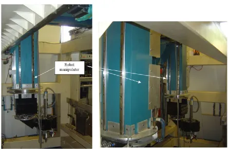
Figure 6: Robot manipulator………..………..53
Figure 7: Two arms of InFACT………...……….66
Figure 8: robot electric actuator and manipulator………. 53
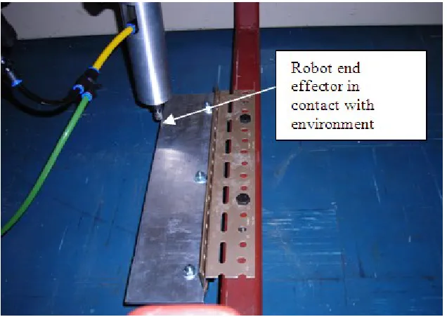
Figure 9: robot interaction with environment ………55
Figure 10: Calibration of the motor current to force ………..55
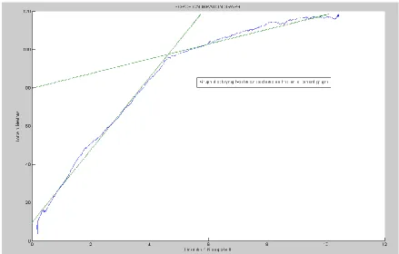
Figure 11: Calibration of the electric motor current to force with two linear regions..57
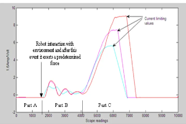
Figure 12: Graph showing torque/current limiting values over 10 seconds interval. 57 Figure 13: The force vector components and ft and the resultant force vector.. 58
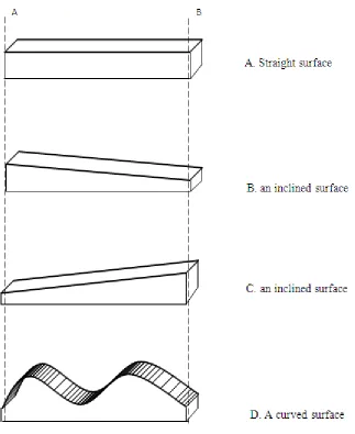
Figure 14: Different geometric surfaces used for 2 dimensional contour following with the knowledge of starting (A) and finish (B) points……….. 59
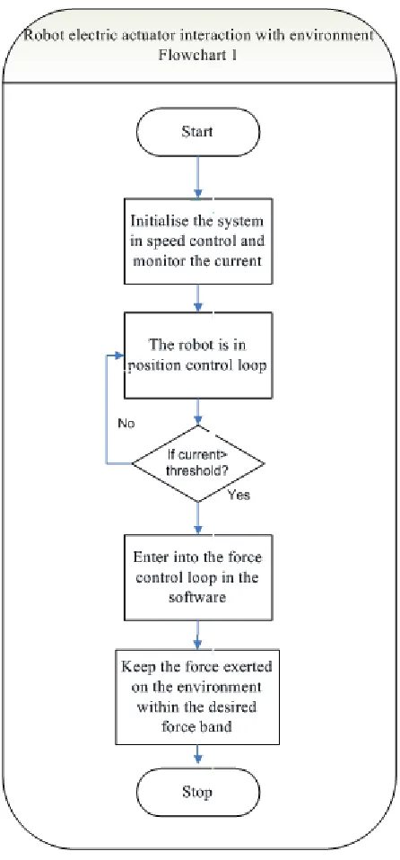
Figure 15: Flowchart describing robot electric actuator with the environment…. 61 Figure 16: Flowchart describing robot electric actuator with the environment for two dimensional surfaces………. 63
Figure 17: Flowchart describing robot electric actuator with the environment for two dimensional surfaces……… 65
Figure 18: Block representation of a process with input output variables ………67
Figure 19 - A Traditional PID Controller………... 72
Figure 20: Different values of ζ calculated from the step inputs to the plant……..…..76
Figure 21: Different values of ω calculated from step inputs to the plant………..76
Figure 22– Simulink model for the PID controller implementation and comparison with plant open loop response. (Kp=1.4, Ki=2.8, Kd=0.18)……….. 76
Figure 25: Force profile while following a straight surface……….79
Figure 26: Force profile following an inclined surface………..80
Figure 27: Example of membership functions……….. 84
Figure 28: Fuzzy logic membership functions example……….. 84
Figure 30: Design of the Fuzzy Controller for 2D surface following………..89
Figure 31: Design of Tagaki Sugeno fuzzy logic controller and specifying inputs and outputs ………90
Figure 32: Force signature while following an inclined surface using fuzzy logic… ………91
Figure 33: Comparison between the PID and Fuzzy Controller for geometrical profiles ………93
Figure 34: Comparison between the PID and Fuzzy Controller for geometrical profiles ………94
Table 35: Performance comparison between PID and Fuzzy Controller on the experimental rig ……….95
Figure 36: Modified Controller structure for PID+Fuzzy controllers……… 97
Figure 37: Profile of the surface following using the modified control strategy… 97 Figure 38: Top View of the ezdsp F2812 Board……….. 115
Figure 39: Force profile following a curved surface……….. 121
Terminology and Nomenclature used in the research work:
q
V : q axis stator voltage
: flux linkage
q
: q axis flux linkagei
u : Integral term
i
T : integral time
p
K : proportional gain
s
: amplitude of stator flux linkage
Kconv :constant used for force to torque conversion
d: the d axis flux linkaged
I : d axis stator current
d
V : d axis stator voltage
e
T : electromagnetic Torque
q
I : q axis stator current
f
: rotor flux linkage
s
R :stator resistance
L
: stator self inductance and with the d and q subscripts represents inductances for those axese :control error
F : force exerted by the robot on the environment.
d
u : derivative term
d
T :derivative time
0
u : nominal value of control variable
p
u :Proportional term P : number of poles
δ : angle between stator and flux linkage
ω : electrical angular velocity of the rotor
*
r ds
i
,
*
r qs
i
, r
: inputs to the inverse Park transform as described in Chapter 4
*
u
i
i
v*i
w* : outputs to the inverse Clarke transform as described in Chapter 4*
ds
i
*qs
i
: inputs to the inverse Clarke transform as described in Chapter 4
r ds
i
rqs
i
:outputs to the Park transform as described in Chapter 4qs
i
i
ds: inputs to the Park transform as described in Chapter 4
ds
i
i
qs: outputs to the Clarke transform as described in Chapter 4
u
Abbreviations:
AC motor : Alternating Current Motor ADC :Analog to Digital Converter BIT: Bristol Institute of Technology B : Damping of the mechanical spring CAN: Controller Area Network
CCS :Code Composer Studio Software environment CFRP : Carbon Fibre Reinforced Plastic
CMM : Coordinate Measurement Machine CNC : Computer Numeric Control
DAC :Digital to Analog Converter DC: Direct Current motor
DSP : Digital Signal Processing FL: Fuzzy Logic
FSV :Full Scale Value
GPIO: General Purpose Input Output
InFACT: Integrated Flexible Assembly Cell Technology IO: Input/Output port
K : mechanical spring constant MIMO: Multi Input Multi Output P : Proportional controller
PC: Personal Computer
PI: Proportional Integral controller
PID: Proportional Integral Derivative Controller PMSM: Permanent Magnet Synchronous Motor PWM: Pulse Width Modulation
RCC: Remote Centre Compliance
SISO: Single Input Single Output system SPI: Serial Peripheral Interface bus TI: Texas Instruments
Thesis Structure and Summary
Chapter 1
:
Introduction:In this chapter, introduction of the research is described. Afterwards the
motivations, research objectives of the presented work are explained to aid the
reader.
Chapter 2
:
Literature Survey:This chapter explains the specific field of research to which this work relates to. It
explains the justification and the inspiration of the work undertaken. The detailed
explanation is carried out of the potential application areas of the proposed control
philosophy.
Chapter 3:
Mathematical representation of the PMSM:The mathematical representation of the PMSM is described in this chapter which
forms the basis of the proposed control philosophy for the electric actuators. The
chapter also describes the introduction of the force controlled behaviour in the robot
joint drive actuators.
Chapter 4:
Development of the experimental setup:
The chapter begins with the description of the experimental setup used in the
research. It describes the data acquisition and interpretation of the controller signals.
The calibration experiments related to force exerted on the environment and the
motor current is described in this chapter. The initial basic development is explained
Chapter 5:
Development of PID Controller:This chapter gives an introduction and justification for the PID controller. The
chapter then explains the modelling and implementation of the PID controller on the
robot gantry experimental setup. The tests are conducted on the experimental setup
for contour following applications.
Chapter 6:
Development of Fuzzy logic controller:This chapter presents the justification for the introduction of Fuzzy controller in the
software for torque control on the present experimental rig. The chapter describes
the approach adopted in the design of the fuzzy controller. The fuzzy controller is
designed and implemented on the experimental setup for torque control. The tests
and results are presented and compared with PID controller. The research work is
then focussed on the design of controller using both the PID and the fuzzy controller
for interaction with complex geometrical contours.
Chapter 7:
Main Contributions and Conclusions:This chapter presents the main contributions of the most salient points made
throughout the thesis, along with the examination of how the work undertaken has
addressed the issues raised in the research questions.
Chapter 8: Future Work:
Fruitful ideas for future work are identified and are discussed further in this chapter.
Some new areas are depicted- some are future-work while the rest are modifications
Appendices:
The appendices provide an abundance of ancillary information for the project.
Whilst the main chapters explore the theoretical background and results of practical
tests, the appendices provide more practical aspects of the research such as the
controller introduction and its operation and the entire software code for the
Chapter 1
1. Introduction
1.1 Introduction and Motivation of the Research
Automation (ancient Greek: self dictated) or industrial automation or numerical control is
the use of control systems such as computers, to control industrial machinery and
processes, reducing the need for human intervention [Dictionary Reference, 2008]. Robot
automation plays an increasingly important role in industrial applications and global
economy. Engineers strive to combine automated devices with mathematical and control
tools to create complex systems for a rapidly expanding range of industrial applications.
Robot automation improves quality, speed, production and cost. It has found numerous
applications in material handling applications such as pick and place, packaging, and
robotic assembly and manufacturing applications such as polishing, deburring, spot
welding and grinding.
Robotics has matured as a system integration engineering field defined by M. Bradley as
“the intelligent connection of the perception to action”. Programmable robot manipulators
provide the “action” component. A variety of sensors and sensing techniques are available
to provide the “perception” of the interaction with the environment [Petriu et al, 2008].
The industrial robot applications such as cranking a wheel, twisting a screw or deburring a
or object. This interaction is aided with elastic pads or springs inserted in the robot end
effector or sensors such as position sensors, vision sensors, force sensors, proximity
sensors. The insertion of springs or elastic pads aids to limit the interaction forces between
the robot end effector in order to avoid damage to the surface or object in deburring,
polishing applications. The position, vision, force sensors are used to give feedback to the
robot controller and therefore the controller can take appropriate actions to bring about the
required motion in the electric actuators of the robot arm, and thereby in the robot structure,
to attain the desired outcomes.
There is an inherent disadvantage in the inclusion of the sensors in the robot controller
structure. The acquisition, interpretation and utilization of the sensory information in the
controller can affect the responsiveness of the robot to external changes. Another
disadvantage is the cost and unsuitability to adapt to different working conditions. The
different working environments also demand compliance in the traditionally stiff robot
structures. This is important so that the interaction of the robot end effector with the
environment can be controlled precisely and accurately. Compliance can be introduced in
an active or a passive manner in the robot structure. The use of mechanical springs or
elastic pads is termed as a passive manner of introducing compliance. This method has
limited performance and lack of adaptability to different applications. The amalgamation of
pneumatic system in the robot end effector introduces active compliance in the system but
the cost, difficulty of control remains the main drawbacks.
Robot applications such as grinding, surface finishing operation like deburring require the
Output (MIMO) system. The research focuses on the inherent architecture of the robot
without any additional or subordinate sensors connected to the robot. The aim is the precise
and accurate control of the robot joint electric motors and introduction of active compliance
in the system. The performance of the electric motor is varied in accordance with the
environmental constraints. The motor current is used as an indicator for torque and shaft
encoder data provides the necessary feedback information to enable motor control to be
exercised. Thus the robot interaction with external object or surface is made programmable
in real-time applications. The advantages are less cost, less acquisition and the utilization
for the interpretation of force information and the varied performance based on external
conditions or desired applications.
The outcome of the research can be applied to processes such as assembly, grinding,
deburring and potentially coordinate measurement systems. The experimental work is
carried out on a permanent magnet synchronous motor. The experimental work can also be
extended to both permanent magnet and brushless DC motors.
1.2 Research Objectives
To develop a software based controlled behaviour in the joint electric actuator so
that the interaction of the actuator, and thereby the robot, is made programmable in
real time applications and to exhibit this behaviour when the robot interacts with the
environment.
To develop and implement software architecture for a two dimensional contour
following force control strategy based on the accurate torque control of the electric
To engineer the robot force control system that will traverse two dimensional
artefacts without previous geometrical knowledge and within a configurable force
deviation tolerance range.
To design and validate control strategies such as the conventional PID control and
fuzzy control to obtain a stable, accurate and reliable system; controller selection
being based upon the optimum performance under various operating conditions.
To provide a survey of various research and manufacturing areas where this
innovative control strategy can be applied.
1.3 Adopted Research Strategy
The experimental studies of the research are carried out on a robot gantry manipulator at
the University of the West of England (UWE), Bristol. A generalised study and inspection
is carried out on the rig. The electric actuator used in the research is a Permanent Magnet
Synchronous Motor (PMSM) but the control philosophy demonstrated is applicable to
other electric actuators. The research is focused on automation of manual deburring
although it can be extended to other applications. A broad literature survey is performed.
An experimental study is also carried out with a force sensor connected to a robot arm and
Design and implementation of the controller and data acquisition boards is carried out and
introductory experiments are conducted on the test rig for two dimensional contour
following. Calibration experiments are performed on the experimental setup for
torque-force relationship.
A two dimensional contour following robotic system based on torque control of the
electric actuator is designed and implemented for surfaces with unknown geometry.
The data acquisition, which included, current feedback is employed on practical
experimental setup. Contour following experiments were carried out on different surfaces
with unknown geometry.
Mathematical representation of the electric actuator is carried out and is validated on the
rig to demonstrate force control behaviour in the real actuator. The force control of the
actuator is made programmable so it exhibits active compliance.
PID controller design and implementation is carried out to give a stable, reliable and
repeatable robotic system. Simulation studies are performed and validated on the
experimental setup.
With an aim to incorporate control strategies for complex environments for automation
applications like deburring, fuzzy control is considered and tested. A switching
mechanism is developed between the conventional PID and fuzzy controller and,
depending on the environment conditions; a combination of both the controllers can be
The research carried out is focussed on automation of robotic deburring but this research
can be extended to various other robotic applications. Therefore, a detailed research
Chapter 2
2. Literature Survey
2.1 Introduction
A robot is defined in many ways: "A reprogrammable, multifunctional manipulator
designed to move material, parts, tools, or specialized devices through various
programmed motions for the performance of a variety of tasks" [Robot Institute of
America definition, 1979]. "An automatic device that performs functions normally
ascribed to humans or a machine in the form of a human." [Webster Dictionary]. The first
definition is restricted to what a robot manipulator is doing in a mechanical sense. The
second definition is more general but still limited to what robots are supposed to do.
The basic idea of a practical robot is to replace humans in repetitive, dangerous, or tiring
tasks. As these repetitive, tiring jobs were found on production lines in industries,
Industrial robots were the first real beings to enter our world as operating machines. Cars,
electronic devices to consumer home appliances today are manufactured by automated
machines or “industrial robot” that replace the common worker in the production line.
1. A mechanical structure or manipulator that consists of a sequence of rigid bodies
(links) connected by means of articulations (joints); a manipulator is normally
characterized by an arm that ensures mobility, a wrist that confers dexterity, and an end
effector that performs the task required of the robot.
2. Actuators that set the manipulator in motion through actuation of the joints, the motors
employed are typically electric or hydraulic, and occasionally pneumatic. Actuators are
needed to perform motion or manipulation in the external world.
3. Sensors that measure the status of the manipulator and, if necessary, the status of the
environment.
4. A control system (normally a computer) that enables control and supervision of
manipulator motion.[Sciavicco et al, 2000].
2.2 Literature review
Traditional/Conventional industrial robotic tasks, which are generally related to
manipulation or assembly, require only control of the position of the robot arm. The
managing of the robot interaction with the environment by adopting a purely motion or
position control strategy turns out to be inadequate for tasks like grinding, deburring or
composite layouts. Implementation of all these tasks intrinsically necessitates that a robot,
besides realizing the predisposed position, provides the necessary force to either
overcome the resistance from the environment or to comply with the environment. Also,
the unavoidable modelling errors and uncertainties in these applications may cause a rise
of the contact forces ultimately leading to an unstable behaviour of the robot arm during
During the early work on telemanipulation, the use of force feedback was introduced to
assist the human operator in the remote handling of objects with a slave manipulator.
More recent research has been conducted on cooperative robotic tasks have been
implemented such as fingers of a dexterous robot hand where the robot force control is of
crucial importance as it has to limit the exchanged forces and avoid squeezing of a
commonly held object. Robot force control is used widely because autonomous field
robots for heavy industry must be rugged and reliable. Force control in industrial robotics
has been a key research area to increase robot performance and to introduce new
functionalities for the last 30 years and has been documented in research articles. Also, in
robot force feedback for deburring and grinding tasks and automated solutions have been
proposed and implemented. [Raibert and Craig, 1981, Siciliano and Villani, 2001,
Brogardh, 2007 Lu et al, 1992 Aertbelien et al, 1999]
Precise position and force control is required for applications such as assembly of
precision-component systems, grinding and deburring. A classification of robot force
control algorithms based on application of the relationship between position and applied
force or between velocity and applied force, or the application of direct force feedback, or
their combinations includes:
methods involving the relation between position and applied force;
methods applying the relation between velocity and applied force;
methods applying directly position and applied force: hybrid position / force
control, and hybrid impedance control;
[Salisbury, 1980, 1982, Borrel, 1979, Whitney, 1977, 1987, Colbaugh, 1992, Mason,
1981, Raibert, 1981]
The two basic approaches to force control are Hybrid and Impedance control [Hogan,
1985]. Hybrid control [Raibert, 1981] is based on the decomposition of the workspace
into purely motion controlled directions and force controlled directions. In Hybrid
control, both a motion controller and a force controller are implemented but the force
controller is given precedence. The insertion of a peg in a hole can be achieved using
hybrid force decomposition. The position error is changed proportionally to the equivalent
force error in the working space first. This is transformed to joint torque error and then
fed to the controller. The controller also compensates for the friction force. The force can
be applied to a direction orthogonal to the position control [Raibert, 1981]. Impedance
control is similar to pure position control where a desired velocity is commanded, except
that the impedance of the robot is regulated to avoid excessive force build-up. Impedance
control [Hogan, 1985] does not regulate motion or force directly but regulates the ratio of
force to motion which is the mechanical impedance.
Impedance control is robust while making contact with unknown surfaces. Hybrid control
has to be divided into two modules: one for free space motion and the other for impact
transition for dealing with unknown surfaces. The advantage of a hybrid controller over
Impedance control is that the contact force can be regulated accurately [Hogan, 1985
Schutter, 1997 Raibert, 1981 and Sung-Hyun Han, 1999]. In the presented work, Hybrid
force controller has been used and the force and motion control strategies are separate in
To achieve robot force control, the adoption of sensors is of crucial importance to achieve
high-performance robotic systems. These are divided into two classes: proprioceptive
sensors and heteroceptive sensors. The former are joint position, joint velocity and joint
torque sensors which measure the internal state of the manipulator while the latter are
force sensors, proximity sensors, range sensors and vision sensors that provide the robot
with knowledge of the surrounding environment. The goal of these sensors is to extract
features characterizing the interaction with environment, thus enhancing the degree of
autonomy of the system. Sensing is particularly difficult because industrial environments
are often dirty, dusty and noisy, both acoustically and electromagnetically. For these
conditions, force sensing is one of the most appropriate technologies, because it is
relatively insensitive to these factors, is well developed and economical. This force
information is used for path modifications in the robot controller to achieve the desired
operation [Sciavicco et al, 2000].
Robot interaction with the environment can be controlled by the inclusion of sensors
which feedback the force data. The force signals are used in a path trajectory controller to
make the required changes in the robot path. It is crucial to adhere to the required forces
on the environment, otherwise too much force could damage the surface/environment or
too little force could not give the desired results perhaps even losing contact with
environment. One solution is to have a mechanical device (remote centre of compliance)
interposed between the manipulator end effector and the environment which has high
stiffness in one direction and high compliance in the other directions, which can avoid
method are rigidity of the device, cost, and failure to adapt to different environments.
Therefore, another solution is preferred where the force acting on the environment can be
monitored in real time and the robot can comply with either the desired trajectories or set
force bands. This is active compliance [Siciliano & Villani, 2001].
Force sensors usually consist of an array of strain gauges which delineate the linear and/or
rotational components of the vector force along the three/six axes of the sensor coordinate
frames [Sponge, 1989]. Measurement of force and/or torque is usually reduced to
measurement of the strain induced by the force (torque) applied to an extensible element
of suitable features. Therefore, an indirect measure of force is obtained by means of
measurements of small displacement. The basic component of a force sensor is the strain
gauge which uses the change of electric resistance of a wire under strain. The strain gauge
is constituted by a wire of low temperature coefficient. The wire is disposed on an
insulated support which is glued to the element subject to strain under the action of stress.
As dimensions of the wire change, they cause a change of electric resistance. Design
parameters are chosen in such a way that the resistance changes linearly in the range of
admissible strain for the extensible element. To transform changes of resistance into an
electric signal, the strain gauge is inserted in one arm of a Wheatstone bridge which is
balanced in the absence of stress on the strain gauge itself.
The sensor type which has gained a lot of industrial and academic attention is the six axis
force/torque sensor. The sensor is used widely in industrial applications with increased
product quality and reliability. However, the force sensors, in general, have some
2007].The speed of response; in particular can have a significant effect on the efficacy of
this approach. Also, force sensors are expensive, can be damaged whilst in operation. The
force data from the sensor needs to be acquired, modified and then utilised in the
controller structure which is difficult. Therefore, the precise utilisation of the force signal
becomes a crucial issue in these applications; otherwise it may lead to robot actuator
saturation or damaging the object/ work-piece.
Some research in robot force control focuses on using the position feedback and relating
the velocity with the force exerted on the environment. Thus, the position feedback is
calibrated to force values exerted on the environment and, in real time applications,
knowledge of the environment can be obtained by monitoring the robot position [Siciliano
& Villani, 2001]. In [H. Kawasaki et al, 2006], research has also been carried out without
using a force sensor but by observing the joint position and velocities of the robot arm.
Thus, research has been conducted on force feedback without a force sensor.
But in these researches, the inherent stiffness of the robot arm is not changed or altered.
This makes sense in traditional position controlled robot systems where high stiffness
reduces instability. But lower interface stiffness has advantages such as more accurate and
stable force control and less damage during inadvertent contact. This alteration in the
stiffness aids in the controlled interaction with the environment and improvement in the
2.3 Introduction and Justification of the research undertaken
Automation of manufacturing tasks like deburring and polishing require introduction of
science into traditionally art based processes. The aim is to design and implement
complex behaviour in the control structure. This is introduced in a robotic system or a
Computer Numerical Control (CNC) machines by force control strategies. The force
control methods can be broadly implemented as rigid structures and compliant structures.
With conventional rigid structures/tools it is very difficult to control the interaction with
an object/surface.
Compliance is the ability of an object to yield elastically or in a spring like manner when
subjected to a force. Compliance control is very important and it is normally introduced in
the system with the addition of external sensors such as mechanical springs and
pneumatic actuators which are unadoptable to different geometrically varying surfaces
and difficult to control respectively.
Adaptive force control is crucial during this interaction as the operation demands the
alteration of the performance during the process execution. An example is the need for the
increased grip force when pressing against a spring as more force is required as the spring
is compressed. Another example of adaptive control is the application of more power to a
motor to maintain a constant speed, as when a robot moves from a level ground to an
This research aims to provide this type of adaptive compliant behaviour in an electric
actuator attached to a mechanical system without the above mentioned external sensors.
The goal of the research is the control of the electric actuator wherein a stable and
specified contact force with the environment is to be maintained. The research work aims
to develop this innovative approach by the control of electric actuators. Instead of
generating this force data through a mechanical and rigid force sensor, force information
can be obtained from the electric actuators (PMSM) driving the robot arm.
Brushless AC servo drives are increasingly used in high performance positioning systems
such as robots and manipulators because of their excellent parameters compared to
conventional DC motors or induction motors. The power density of a PMSM is higher
than the induction motor due to the fact that there is no stator power dedicated to magnetic
field production. These motors are controlled by techniques such as Vector control. In this
method, the position feedback from the motor rotor is required to transform the three
phase variable into two phase axes frame in the synchronously rotating reference frame
aligned with the rotor flux linkage vector. This is done to maximise the torque supplied by
the motor. Research on the control and performance of PMSM has been carried out and
documented in articles. [Schutter et al,1986, Kaewjinda, 2007 and Pillay et al, 1988, 1989,
Vector control, NEC application notes, 2002]. Research has been done on the precise
modelling and method of operation of PMSM [Pillay et al, 1988, 1989]. In [Hyungbinet
al], the dynamic behaviors of a BLDC motor are analyzed, when the motor undergoes
mechanical and electromagnetic interaction due to an air gap variation between the stator
The motor current reflects the torque of the actuator and thereby the force of the system
[Sponge et al, 1989]. The torque of the motor can be altered depending on the load on the
system and hence the force exerted by the system. Thus, the motor current can be
calibrated to reflect the force exerted by the manipulator on the environment. By
achieving this, we are able to introduce active compliance in the system. The robot
interaction with the environment can be made programmable and the force exerted can be
changed. Thus, the electric actuator behaves as a programmable spring. The contact force
depends on the robot joint actuator stiffness. The stiffness can be varied to yield elasticity
or a spring like behaviour when a force is applied, thereby introducing compliance in the
system. Therefore, the need for an external force sensor is avoided.
Using an adaptive controller for real time applications like grinding and deburring
requires a powerful processor. Nowadays, the development of new materials, the
improvement in the mechanical design of robot manipulators and faster microprocessors
have highlighted the necessity of applying more sophisticated control algorithms in the
new generation of industrial robotics [Siciliano and Villani, 2001]. An adaptive controller
continuously tracks plant parameters and constantly, or periodically, modifies the
parameters of the control system to provide optimum performance. To achieve this, a
Digital Signal Processor (DSP) is required.
Significant research in intelligent and Adaptive control has been performed based upon
the PID control, fuzzy control and neural network approaches. PID controllers are
extensively used because of the advantageous properties they exhibit such as robustness,
environment, sometimes the preferred solution is fuzzy control or neural networks, which
aim to incorporate more complex behaviour and reasoning skills in the automation of
robot operations to handle non-linearities. Fuzzy control has become a popular approach
for performing the task of controller design because the human reasoning skills can be
incorporated in the controller structure. Therefore, fuzzy control is often applied to some
ill-defined systems. This explains the current trend in the theoretical development to
combine fuzzy control techniques with conventional PID control techniques to obtain
adaptive fuzzy control.
For example, in [Ahn et al, 2011] an online smart tuning fuzzy PID approach based on a
robust extended Kalman filter for the development of high force control precision is
presented, where force or position control with high accuracy is exceedingly necessary. In
[Hamit] a neurofuzzy controller has been used to linearlize the highly nonlinear sensor and
motor output signals.
In some cases, industrial robot operation demands high accuracy performance that is not
achievable by using a conventional PID control. In [Kaitwanidvilai, 2004], the concept of
switching between a PID controller and a neurofuzzy controller has been implemented on
a pneumatic system. The experimental results have confirmed that the concept of
multimode switching yields better results than classical control or the neurofuzzy
controller acting alone. Research has been documented in articles. [Trusca, 2003, Burn,
2.4 Application Areas
Robot force control can be used for various robot automated operations like polishing,
assembly and deburring. The automation of the preceding mentioned applications is often
restricted because of the complexities associated with the applications. Therefore, in some
cases, manual work option is still given precedence to automated operations. The research
can be applied to these applications because the performance of the robot electric actuator
can be varied in real time in accordance with the environmental constraints. This proposed
control philosophy aims to include these complexities and non linearities in the adaptive
control structure.
Automated Deburring applications-
A burr is a sharp and raised edge that is formed in several manufacturing processes such
as milling, drilling, turning and other machining operations. These burrs have to be
removed for ergonomic, aesthetic, and/or functional reasons. A small series of large
components pose a problem and are most often manually cleaned with a grinding tool.
Manual deburring techniques have disadvantages such as poor working conditions,
production delays and inconsistent work quality. The robot should have a stable force
control throughout the entire machining process. Automation normally requires the
detailed knowledge of the environment beforehand. Automated robot deburring systems
are becoming crucial as the cost of manual deburring can be around 30-35% of overall
production costs [Murphy, 1990 Hsu, 2000]. Several problems prevent a breakthrough in
this area which includes variations in the work piece position which are unavoidable
systems cannot be used on small series of components. Due to the nature of the processes
such as casting and forgings, work pieces commonly have high geometrical inaccuracies.
These factors limit the use of traditional position controlled robots. Other sensors can be
used to solve these problems. Force feedback is a good candidate, but its use necessitates
specific control strategies that depend on the type and size of the burrs, the materials of
the work-piece and grinding tool, and the task goals.
The presented work has been researched and implemented and can be applied to robotic
deburring. To achieve this goal, a cutting tool with a fixed spindle speed has to chamfer
the part edges while undergoing contour-following motion. While driving the cutting tool
to perform a deburring process, the deburring robot must implement two major motions.
One motion applies a suitable chamfering force to the part‘s edges to remove the burrs
while avoiding damage to the part. The other motion performs contour following. This
ensures the cutting tool remains in contact with all the burrs over the chamfer by
appropriate torque control. A heuristic deburring control policy can attain the desired
chamfering force by controlling the feed-rate of the cutting tool. The heuristic policy
simply consists of slowing down the feed-rate of the cutting tool when the encountered
burr is large, and speeding it up if otherwise [Kazerooni, 1987, Lu et al, 1992 Hsu
Feng-Yi et al, 2000].
Most industrial robots rely on teach programming, a process that is tedious and time
consuming. An alternative method uses Ccomputer-Aided Design (CAD) data and a
representation of the robot’s environment to compute manipulator coordinates off-line.
alone, and it is ineffectual without on-line modification. Finally, for a work piece with
partially unknown contours, planning a trajectory may be infeasible. An alternative
approach could be to use accurate on-line trajectory teaching via the work piece’s surface
geometry; a roller bearing, or a properly designed jig, is mounted on the robot
end-effector. However, these machines are very expensive and frequently cost too much to
justify their use in a deburring applications. Also, the mechanism is more complex [Seng
Chi-Chen et al, 1999, 2000].
Researchers have worked on automation of deburring and polishing on unknown
geometrical contours. Research has been done in these industrial operations but a majority
of them rely on the force signature from the additional mounted sensors on the end
effector [Garcia et al,2008, Seng Chi-Chen, 1999, 2000].
Coordinate measurement machines-
Another application is coordinate measuring machines. Coordinate measurement
machines (CMM) also demand a precise and accurate force and position control of the
component. The overall measurement time of the component can be reduced if the
actuators are introducing the compliance rather than at the probe used on the end of the
arm in CMM. The compliance behaviour in the electric actuators will allow a certain
specified position error to develop between the probe and the component to be measured.
This control philosophy can also been implemented in biomedical engineering research
Composite layout force control-
The new Boeing B787 and Airbus A380 are seen as an indication of a step change in the
use of composites in commercial aviation. The aircraft industry is undergoing a rapid shift
to composite materials in the development programmes for new aircraft and is facing
what it calls a ‘historic expansion of demand for such materials’. The use of reinforced
plastic in aircraft has grown enormously since the early 1970. The challenge now is
increasing the use of this composite material throughout the aircraft in order to increase
durability, decrease weight (thus increasing fuel efficiency) [Airbus, 2007].
The composite material used in aircraft in layers, with adhesive applied in-between each
layer. The aerospace industry is producing composite material called Carbon Fibre
Re-enforced Plastic (CFRP) and a significant proportion of its manufacturing involves high
precision work performed by skilled labourers. Segments of the fuselage and the other
large artefacts are manufactured by existing robotic systems, but the more intricate,
complex geometrical shapes (aerodynamics) are considered to be outside the robot
capabilities. This is because the workers who perform these tasks possess skill, knowledge
and experience that arise from the intimate involvement with the environment and
involves very accurate force and position control. This is a complex non-linear,
multivariate control environment [Airbus, 2007].
The current research can be applied to these applications where compliance and stiffness
of the system are real time programmable and aims to include complex behaviour in these
automated robot operations. Thus, the presented research work focuses on the torque
contours with desired force values. Therefore, this novel control philosophy which
eliminates external sensors and also introduces spring-like behaviour in the electric
Chapter 3
3. Mathematical modelling of the electric actuator (PMSM) for
the controlled interaction with environment
Introduction
There is a vital interface between electrical and mechanical engineering. Wherever
mechanical motion is controlled by electronics, it is commonly referred to as a part of
“Mechatronics” [Miller, 1989]. Mechatronics involves control of mechanical motion
control systems in industrial, manufacturing and technological processes. The motion
control systems aim to achieve the specified performance demanded by users and industrial
standards in electric actuators [Lyshevski, 1999]. The electric actuator used in the research
work is a PMSM which requires a sophisticated electronic control, called Vector Control.
Motion control in Robotics is a long established and well understood field and forms the
basis of most modern manufacturing technology. The demand for high accuracy and
repeatability is traditionally achieved by employing high stiffness mechanisms with
3.1 Mathematical representation of a PMSM
The PMSM used in servo-mechanical systems is generally called “a brushless servomotor”
or “brushless AC servomotor” [Kaewjinda et al, 2007]. As results of the progress in power
electronics, software engineering, and materials, the PMSM, based on modern rare earth
magnet variety, has become a serious competitor to the induction motor and conventional
wound rotor synchronous motor. PMSM drives are used in many applications. They are
receiving increased attention because of their high efficiency, and small size. The PMSM is
preferred, in industrial servo applications, to the DC motor due to considerations of the
cost, size, low maintenance, maximum speed, capability, and simplicity of design. The
power density of a PMSM is higher than that of an induction motor with the same ratings,
due to no stator power dedicated to the magnetic field production. For this reason, they
have evolved into the preferred solution for speed and position control drives on machine
tools and robots. They are used in applications which require rapid torque control and high
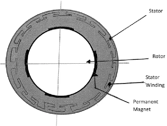
Figure 1: Permanent magnet synchronous motor (PMSM)
The PMSM, as shown in Figure 1, is a rotating electric machine where the stator is a classic
three phase stator, like that of an induction motor, and the rotor has surface-mounted
permanent magnets. In this respect, the PMSM is equivalent to an induction motor where
the air gap magnetic field is produced by a permanent magnet. The use of a permanent
magnet to generate a substantial air gap magnetic flux makes it possible to design highly
efficient PM motors.
For a common 3-phase PMSM, a standard 3-phase power stage is used. The same power
stage is used for AC induction motors. The power stage utilizes six power transistors with
independent switching. The power transistors are switched in the complementary mode.
A PMSM is driven by a sine wave voltage coupled with the given rotor position. The
generated stator flux, together with the rotor flux, which is generated by a rotor magnet,
defines the torque, and thus the speed of the motor. The sine wave voltage outputs have to
be applied to the 3-phase winding system in such a way that the angle between the stator
flux and the rotor flux is kept close to 90° to get the maximum generated torque. To meet
this criterion, the motor requires electronic control for proper operation, called Vector
Control. This is facilitated by the use of modern DSP and microcontrollers to attain the
functionality, flexibility and reliability required for the accurate torque control in electric
actuators.
Vector control is easily understood by forming a mental image of the coordinate reference
transformation process. If an AC motor operation is visualised from the perspective of the
stator, a sinusoidal input current applied to the stator is observed. This time-variant signal
generates a rotating magnetic flux. The speed of the rotor is a function of the rotating flux
vector. From a stationary perspective, the stator currents and the rotating flux vector look
like AC quantities.
The picture is visualised being inside the motor and running alongside the spinning rotor at
the same speed as the rotating flux vector generated by the stator currents. If the motor is
observed from this perspective during steady state conditions, the stator currents look like
Ultimately, the aim is to control the stator currents to obtain the desired rotor currents
(which cannot be measured directly). With coordinate reference transformation, the stator
currents can be controlled like DC values using standard control loops.
In vector control drives, the highly accurate position, derived from a position sensor, is
required to transform the three variables of the three phases (abc) to the two variables (dq)
in the synchronously rotating reference frame aligned with the rotor flux linkage vector.
The stator flux linkages, voltage and electromagnetic torque equations in the dq reference
frame are as follows:
d q d s
d R I p
V ………...……….……… (1)
q
V Rs Iq d pq ….………...……… (2)
d LdId …….……….………...….… (3)
q q q L I
……….……….……...…. (4)
The electromagnetic torque is given by the following equation for synchronous machines
d q q d
e I I
P
T
Substituting Equations (3), (4) in (5), we have
d d q q d q
e L I I L I I
P
T
2 2 3
q d q d q
e I L L I I
P
T ( )
2 2
3
………..……… (6)
In the above equation, the first term ( Iq) is called as the ‘magnet alignment torque’; and
d
L and Lq have the same value and equal to L, the equation is reduced to,
qe I
P
T
2 2 3 ………..……….… (7)
The d axis current is kept near zero to maximise the torque of the motor and the angle
between the stator, rotor flux linkages is kept 90° in order to maximise the torque output
from the motor. The mathematical proofs for the angle between the stator and rotor flux is
given in Appendix.
From equation (7),
d d q q q d q
e L I I I L I I
P
T
q e
I
T
……….……...………... (8)The torque is directly proportional to the q axis current.
The torque in equation (8) is calibrated to the force exerted by the robot on the
environment. The following equation (9) is obtained, where Kconv constant is used for
torque to force conversion.
F = Kconv * Te………...…..………...……… (9)
Substituting the value of Tein equation (9),
F Kconv P
Iq
2 2 3
...………...………...……….…. (10)
F
I
q ………...………..……… (11)The force of the electric actuator is directly proportional to the q component of the current.
The current is maintained within a predetermined force band and is made programmable in
the software. Therefore, the force exerted by the electric actuator on the environment can be
3.2 Introduction to spring like behaviour in electric actuators
The aim of the research is to look into the introduction of a spring like behaviour in the
robot electric actuator and thereby controlling the interaction of the robot with any object or
surface. When a mechanical spring is considered, the damping (B) and the stiffness (K) are
considered as the two main attributes. The same mechanical attributes are compared with
the electrical analogies.
In a PMSM, the rotating frequencies of the rotor and the stator flux are the same, i.e., no
slip. However, if the rotor speed departs from the steady synchronous value, there is a time
difference before which the stator and rotor flux come into synchronisation. This
characteristic of the PMSM is compared with the damping characteristic (B) of a
mechanical spring. When the motor is given a step speed change it oscillates around the
desired value before settling. This factor gives the damping of the system.
Compliance can be termed as the ability of an object to yield elastically, giving a spring
like behaviour when a force is applied. The torque provided by the motor is directly
proportional to the angle between the stator and rotor flux linkages and the torque is
maximum at an angle of 90 degrees. In the presented work, the amplifier of the motor
always tries to keep the angle at 90 degrees. However, with sophisticated control
techniques, the angle can be reduced and thereby affecting the torque. The torque is also
directly proportional to the magnitude of the stator flux linkage. These two entities affect
(K) of a mechanical spring. This control philosophy will guarantee adaptive stiffness and
compliance can be introduced into the system.
The manipulation of the angle between the stator and rotor flux linkages is not employed in
the research carried out due to the operational limitations of the drive amplifier for the
electric actuator. Thus the electric actuator, with appropriate control strategies, can be
designed to behave as a programmable spring and the interaction with the environment or
the surface can be controlled as desired. The performance of the motor and the stiffness is
Chapter 4
4. Development of the experimental setup for robot interaction
with the environment and initial tests
4.1 Introduction of the system
The proposed research was carried out on a robot gantry manipulator at the University of
the West of England (U.W.E.), Bristol. The following section provides an introduction to
the experimental setup and describes the control system architecture employed in the
research.
Background and Introduction-
The gantry robot machine was built for the InFACT (Integrated Flexible Assembly Cell
Technology) Project, U.W.E. (then Bristol Polytechnic) was the project leader. The aim of
the InFACT project was to build a flexible assembly machine that could assemble a large
range of small consumer products. For this work, only one manipulator is being used. Each
The structure is similar to nearly all commercial robots. The difference is that the entire
gantry has been designed and built at UWE, so it can be modified far more easily than
commercial machines, as there is access to the controller. This machine is aimed at research
tasks so the configuration will change with time. To accommodate the changes, InFACT is
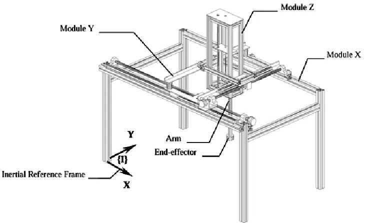
made re-configurable. The basic diagram for one arm with three axis of the manipulator is
[image:47.612.125.491.220.443.2]as shown in Figure 2.
Figure 2: A Generic gantry manipulator layout
4.2 Description of the control system architecture, electrical actuator and
controller
A typical control system has to supervise the activities of the robotic system and is aided
with a number of tools providing the following functions:
1. Capability of moving physical objects in the working environment, i.e., manipulation
2. Capability of obtaining information on the state of the system and the working
environment, i.e., sensory ability;
3. Capability of exploiting information to modify system behaviour in a pre programmed
manner, i.e., intelligent and adaptive behaviour ability;
4. Capability of storing, elaborating and providing data on system activity, i.e., data
processing ability. [Sciavicco et al, 2000]
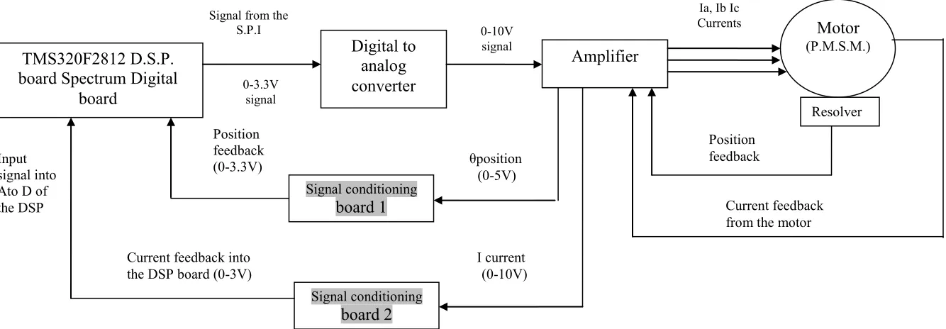
Figure 3: Control system architecture employed in the research
The control system architecture is implemented as shown in Figure 3. The used controller is
the TMS320F2812, a mid-range DSP. DSPs are special purpose microprocessors that are
particularly suitable for intensive numerical computations. Digital versions of most
advanced control algorithms can be defined as sums and product of measured variables thus
can be naturally implemented by DSPs (Z. Ma, 1995). The DSP generates the control signal
which goes to the drive (Infranor amplifier SMTDB) of the motor which, in turn, provides
current to the motor (MA-30 Mavilor). PMSM actuate individual robot gantry axes. All the
electric actuators are installed with a resolver for providing position feedback. The resolver
induction between two electric circuits which allow continuous transmission of angular
position without mechanical limits.
Each motor is connected with two cables. One cable carries electric power to the motor.
The second cable (resolver cable) tells the amplifier cabinet how far the motor has moved
in a positive or negative direction. The motor and amplifier form a separate unit. There is a
current feedback path from the motor and a position feedback path from the resolver on the
motor, as shown in Figure 3. The data sheets for the electric actuator, amplifier and
controller can be found in the appendix I, II and III.
As the research work is performed on a two dimensional gantry manipulator, there are two
DSP boards used in the architecture. The two DSP boards communicate with each other via
a CAN bus interface with a maximum speed of 1Mbps. The experimental setup has been
designed for X-Y two dimensional tasks at present, but it has also a
facility for a Z direction.
[image:49.612.127.524.504.652.2]
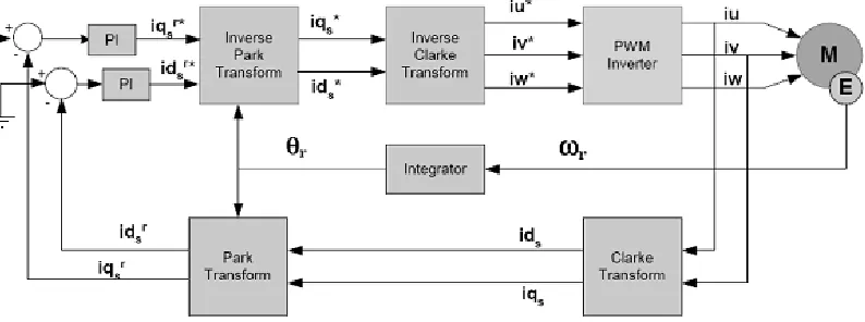
Figure 4: Block diagram of Vector control of an AC motor
The electric actuators on the robot are operated by Vector control. It is an elegant method
of controlling the PMSM which is used to control space vectors of magnetic flux, current,
and voltage. It is possible to set up the co-ordinate system to decompose the vectors into an
electro-magnetic field generating and torque generating parts. Thus, the structure of the
motor controller (vector control controller) is almost the same as for a separately excited
DC motor, which simplifies the control of PMSM. This vector control technique was
developed in the past especially to achieve similar excellent dynamic performance of
PMSM.
The performance of three phase ac machines is described by voltage equations and
inductances. AC machine inductances are functions of rotor speed. The coefficients of the
differential equations which describe the behaviour of these machines is time varying. A
change of variable can reduce the complexity of these differential equations. Therefore,
Clarke and Park Transforms were introduced. The transformation of rotational circuits to a
stationary circuit was developed by E. Clarke. The Park Transform was developed by R. H.
Park. The Park Transform has the feature of eliminating all time varying inductances from
the voltage equations [Toliyat, 2004]. Using these transforms, many properties of the
electrical machines can be studied without the complexities of the voltage equations.
Vector control seeks to recreate the orthogonal components in the AC machine (id and iq)
in order to control the torque producing current separately from the magnetic flux
producing current [Vector Control, NEC, 2002]. The iq and id components of the
reference frame is referenced to