Meta-Parametric Design
Developing a Computational Approach for Early Stage
Collaborative Practice
A thesis submitted for the degree of
Doctor of Engineering
John Harding
University of Bath
Department of Architecture and Civil Engineering
July 2014
COPYRIGHT NOTICE
Attention is drawn to the fact that copyright of this thesis rests with the author. A copy of this thesis has been supplied on condition that anyone who consults it is understood to recognise that its copyright rests with the author and that they must not copy it or use material from it except as permitted by law or with the consent of the author.
This thesis may be made available for consultation within the University Library and may be photocopied or lent to other libraries for the purposes of consultation.
Abstract
Computational design is the study of how programmable computers can be integrated into the process of design. It is not simply the use of pre-compiled computer aided design software that aims to replicate the drawing board, but rather the development of computer algorithms as an integral part of the design process. Programmable machines have begun to challenge traditional modes of thinking in architecture and engineering, placing further emphasis on processahead of the final
result. Just as Darwin and Wallace had to think beyond form and inquire into thedevelopmentof biological organisms to understand evolution, so
computational methods enable us to rethink how we approach the design process itself.
The subject is broad and multidisciplinary, with influences from design, computer science, mathematics, biology and engineering. This thesis begins similarly wide in its scope, addressing both the technological aspects of computational design and its application on several case study projects in professional practice. By learning through participant observation in combination with secondary research, it is found that design teams can be most effective at the early stage of projects by engaging with the additional complexity this entails.
Acknowledgements
This thesis is dedicated to my wife Simone and our daughter Annabel. I am forever grateful.
Thank you to my three supervisors Paul Shepherd, Chris Williams and Duncan Horswill for their expert guidance. I distinctly remember Paul calling me just before I committed to ask “are you absolutely sure you want to do this?!” I forget my reply, but I presume he must have convinced me to say yes and I’m pleased that he did.
Thank you to my friends and colleagues at Ramboll, especially Stephen Melville, Harri Lewis, Andreas Bak, Alex Baalham, Iain Sproat, Tom Foley, Ross Smith, Mark Pniewski, Yanchee Lau, Will Pearson and Kristjan Plagborg Nielsen.
Thank you to those in the computational design community, in particular Sam Conrad Joyce, Robert Aish, Daniel Piker, Gennaro Senatore, Em-manouil Zaroukas, Christian Derix and the late Paul Coates. Paul was an inspiration to all of his former students and we hope his spirit lives on through our work.
Thank you to all the collaborators outside of Ramboll that have given up their time to participate in this research. Particular mention to Charlie Whitaker (3DReid), Daniel Nielsen & Brian Sheldon (AG5 Architects), Jim Dodson (SPINN Arkitekter), Chun Qing Li (Pavilion Architecture) and Catherine Huang (Bjarke Ingels Group) for allowing me to particip-ate on various influential projects that helped shape this work.
Thank you to the Systems Centre at The University of Bristol & The University of Bath, the Engineering and Physical Sciences Research Council and Ramboll UK for jointly supporting this research. Without the EngD programme, my initial meanderings to discover something I didn’t know I was looking for would never have happened.
Contents
I.
Introduction
1
1. Introduction 3
1.1. EngD Beginnings . . . 4
1.1.1. Ramboll and I . . . 4
1.1.2. Ramboll’s Initial Intentions . . . 5
1.1.3. What is Computational Design? . . . 6
1.2. Thesis Objective . . . 8
1.2.1. Computational Design . . . 8
1.2.2. Meta-Parametric Design . . . 9
1.3. Methodology . . . 10
1.3.1. Data Triangulation . . . 10
1.3.2. Primary Research Methods . . . 11
1.3.3. Secondary Research Methods . . . 13
1.3.4. An Adaptive Methodology . . . 13
1.4. Contribution to Knowledge . . . 14
1.5. Chapter Outline . . . 15
II. Review
17
2. Post-Rationalisation 19 2.1. Introduction . . . 192.1.1. Building Models . . . 20
2.2. Heuristic Algorithms . . . 20
2.2.1. Introduction . . . 20
2.2.2. Without External Analysis . . . 21
2.2.3. Consistent External Analysis . . . 26
2.2.4. Incremental External Analysis . . . 30
2.2.5. Summary . . . 35
2.3. Metaheuristic Search Algorithms . . . 36
2.3.1. Introduction . . . 36
2.3.2. Metaheuristic Examples . . . 37
2.3.3. Mapping Process . . . 40
2.4. Parametric Modelling . . . 41
2.4.1. Dataflow Programming . . . 42
2.4.2. Integrating with Building Analysis . . . 43
2.4.3. Integrating with Metaheuristics . . . 45
2.5. Multi-Objective Optimisation . . . 47
2.5.1. Adapting the Parametric Model . . . 48
2.5.2. Handling Requirement Changes . . . 49
2.6. Discussion . . . 51
2.6.1. Engineer as Problem Solver . . . 51
2.6.2. Review of Aims & Objectives . . . 52
3.2. Engineering Led Design . . . 56
3.2.1. Interactive Form-Finding . . . 56
3.2.2. Qualitative Assessment . . . 59
3.2.3. Case Study Results . . . 60
3.2.4. Summary . . . 62
3.3. Introducing Stakeholders . . . 63
3.3.1. Air Baltic Terminal Competition . . . 63
3.3.2. The KREOD Pavilion . . . 65
3.3.3. Summary . . . 66
3.4. Discussion . . . 67
3.4.1. Primary Generators . . . 67
3.4.2. Working Together . . . 68
3.4.3. Concept Design Stage . . . 68
3.4.4. Review of Aims & Objectives . . . 70
III. Working Together
73
4. Early Parametric Design 75 4.1. Introduction . . . 754.2. Why Parametric Models? . . . 75
4.2.1. Working with the Graph . . . 76
4.2.2. A Collaborative Framework . . . 77
4.3. Design Exploration . . . 79
4.4. Implementation . . . 80
4.4.1. Constraints and Objectives . . . 81
4.4.2. Performance Evaluation . . . 82
4.5. Observations . . . 82
4.5.1. Concept Design Exploration . . . 84
4.5.2. A Fixed Body-Plan . . . 85
4.5.3. Design development . . . 86
4.5.4. Possible Solutions . . . 88
4.6. Discussion . . . 89
4.6.1. Relation to Software Development . . . 89
4.6.2. Review of Aims and Objectives . . . 90
5. Freeing the Body Plan 93 5.1. Introduction . . . 93
5.1.1. Evolutionary Development . . . 94
5.2. Artificial Embryogenesis . . . 95
5.2.1. Local Rules . . . 95
5.3. Implementation . . . 96
5.3.1. Modelling . . . 97
5.3.2. Local Rules . . . 97
5.3.3. Performance Objectives . . . 99
5.3.4. User Control . . . 100
5.3.5. Using a Metaheuristic . . . 101
5.4. Observations . . . 101
5.4.1. Collaboration Issues . . . 103
5.4.2. Case Study Evidence . . . 105
5.4.3. Evidence from Industry . . . 107
5.5. Discussion . . . 108
5.5.1. Reconsidering Parametric Models . . . 109
5.5.2. Evolvability . . . 110
IV. Bridging The Gap
113
6. Meta-Parametric Design 115
6.1. Introduction . . . 115
6.2. Genetic Programming . . . 116
6.2.1. Tree Representation . . . 116
6.2.2. Generative Grammars . . . 118
6.2.3. GP for Design Exploration . . . 119
6.2.4. Cartesian Genetic Programming . . . 120
6.3. Embryo . . . 122
6.3.1. Introduction . . . 122
6.3.2. Generating DAGs . . . 123
6.3.3. Embryo Components . . . 125
6.3.4. Constraints and Parameters . . . 125
6.3.5. Encoding and Generation . . . 127
6.3.6. Some Simple Examples . . . 130
6.3.7. Combining with Metaheuristics . . . 133
6.3.8. Cognition . . . 134
6.3.9. Working In-Between . . . 136
6.4. Discussion . . . 137
7. Embryo Experiments 139 7.1. Experiment 1: AG5 Architects . . . 139
7.1.1. Set up . . . 139
7.1.2. Modelling . . . 141
7.1.3. Model Examples . . . 143
7.1.4. Performance Evaluation . . . 143
7.1.5. Model Cognition . . . 147
7.1.6. General Observations . . . 148
7.1.7. Improvements . . . 150
7.2. Experiment 2: 3DReid Architects . . . 152
7.2.1. Set up . . . 152
7.2.2. Modelling . . . 153
7.2.3. Design Exploration . . . 154
7.2.4. Graph Complexity as an Objective . . . 156
7.2.5. Post-Generation . . . 157
7.3. Experiment 3: Shape Analysis . . . 160
7.3.1. A Suitable Metaheuristic . . . 160
7.3.2. Results . . . 161
7.3.3. Increasing Complexity . . . 161
7.3.4. Opening Dead-ends . . . 165
7.3.5. Forget about Legibility . . . 167
7.4. Discussion . . . 169
V. Conclusions
171
8. Conclusions 173 8.1. Meta-Parametric . . . 1738.1.1. Summary . . . 173
8.2. Embryo Results . . . 174
8.2.1. Model Design Space . . . 175
8.2.2. Model Performance . . . 176
8.2.3. Graph Intelligibility . . . 176
8.3. Further work . . . 177
8.3.2. Recursive & Cyclic Structures . . . 177
8.3.3. Hierarchies of Scale . . . 178
8.3.4. Artificial Selection . . . 178
8.4. Final Comment . . . 180
VI. Appendix
199
A. Case Study Details 201 B. Principal Stress Trajectories 235 B.1. Introduction . . . 236B.2. Real-time Software . . . 236
B.3. Calculation Method . . . 237
B.4. Principal Bending Stress . . . 238
B.5. Conclusion . . . 240
C. Structural Form-finding using Springs and Dynamic Weights 241 C.1. Background . . . 241
C.1.1. Zero-length springs . . . 242
C.2. Two-dimensional systems . . . 242
C.2.1. Method overview . . . 242
C.3. Extension to funicular forms . . . 243
C.3.1. Dynamic Weights . . . 243
C.3.2. Real-time exploration . . . 244
C.3.3. Catenary Comparison . . . 244
C.4. Three-dimensional systems . . . 245
C.4.1. Using a Trivalent Topology . . . 246
D. The London Foyer Sculpture 249 D.1. Introduction . . . 249
D.2. Design Strategy . . . 249
D.3. Material & Fabrication . . . 250
D.4. Connection Details . . . 250
D.5. Assembly . . . 251
E. The TRADA Pavilion – A Timber Plate Funicular Shell 253 E.1. Introduction . . . 253
E.2. Funicular Form-finding . . . 254
E.2.1. Computational Approach . . . 254
E.2.2. Zero-Length Spring System . . . 255
E.2.3. Software Application . . . 256
E.3. Planar Re-meshing . . . 256
E.3.1. Triangles & Quads . . . 257
E.3.2. Tri-valent Planar Polygons . . . 259
E.3.3. Free Edges . . . 259
E.4. Fabrication & Assembly . . . 260
E.4.1. Connection Detail . . . 261
E.4.2. Assembly . . . 261
E.5. Conclusion . . . 262
List of Figures
1.1. Location within industry hierarchy . . . 5
1.2. Building model performance criteria . . . 6
1.3. Question hierarchy within wider context . . . 9
1.4. Case study project involvement . . . 12
2.1. Post-rationalising an existing design . . . 21
2.2. Garden Festival minimal surface . . . 22
2.3. Laplacian smoothing on the Lusail Bridge Roof . . . 23
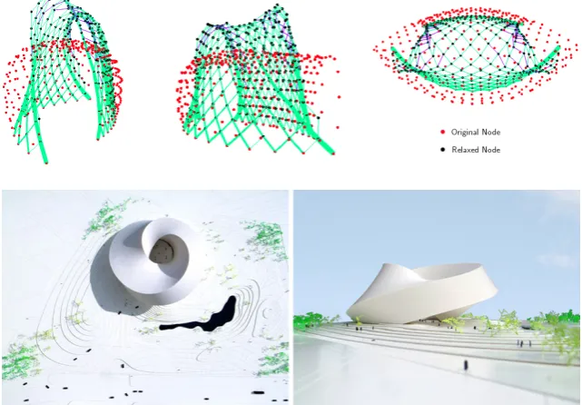
2.4. KREOD surface relaxation . . . 24
2.5. Architectural concept for The Astana National Library . . 24
2.6. Initial facade triangulation for Astana National Library . . 25
2.7. Astana National Library nodal repulsion . . . 26
2.8. Algorithm with external analysis . . . 26
2.9. PQ meshing process . . . 27
2.10. Senate House glazed roof . . . 27
2.11. Orchid House discretisation . . . 28
2.12. Helsinki Central Library: principal bending stress slab . . 29
2.13. Passive solar design Java application . . . 30
2.14. Majlevik Bay Villas: generated roof forms . . . 30
2.15. Algorithm using dynamic external analysis . . . 31
2.16. Node pushing to high stress . . . 31
2.17. Astana Library: nodal displacements . . . 32
2.18. Astana Library node pushing . . . 33
2.19. Tallinn Town Hall topology optimisation . . . 34
2.20. Metaheuristic workflow . . . 37
2.21. Bath House column optimisation . . . 38
2.22. Metaheuristic solver comparison . . . 39
2.23. The process of genotype manipulation for a typical GA . . 39
2.24. Citylife Tower Spire evolution . . . 40
2.25. Direct mapping from genotype to point location . . . 41
2.26. Probably the simplest parametric model ever made . . . . 42
2.27. Exploring façade densities on Arts Alliance . . . 43
2.28. Cheongna Tower real-time structural analysis . . . 44
2.29. Parametric model workflow . . . 45
2.30. Cheonga Tower optimisation . . . 46
2.31. A simple multi-objective problem . . . 48
2.32. Multi-objective optimisation on Cheongna Tower . . . 49
2.33. Cheongna Tower: structural analysis and visualisation . . 50
2.34. Traditional procurement . . . 51
3.1. Design exploration with a heuristic method . . . 56
3.2. The Ongreening Pavilion realised in March 2014 . . . 57
3.3. Mannheim Multihalle hanging chain model . . . 58
3.4. TRADA Pavilion form-finding . . . 59
3.5. A qualitative requirement for TRADA . . . 60
3.6. TRADA Pavilion design exploration . . . 60
3.7. Completed TRADA Pavilion . . . 61
3.9. Node detail on the London Foyer Sculpture . . . 62
3.10. Embedding engineering heuristics in software . . . 63
3.11. Air Baltic Terminal: initial roof geometry . . . 64
3.12. Java application used on the Air Baltic Terminal . . . 64
3.13. Air Baltic Terminal: structural analysis . . . 65
3.14. KREOD: Surface principal curvature for five options . . . . 66
3.15. Unloved ESS competition shells . . . 67
3.16. Freedom vs knowledge plot . . . 69
4.1. Spaghetti . . . 77
4.2. Collaborative model used on the Aviva Stadium Project . . 78
4.3. Escher tower foam models . . . 81
4.4. Constraints and objectives search . . . 82
4.5. Escher tower performance feedback . . . 83
4.6. Karl Sims’ evolving creatures . . . 86
4.7. Different graph definitions leading to an identical form . . 87
4.8. Design process and building model development . . . 90
5.1. The influence of Hox genes on the body-plan . . . 94
5.2. Graph representation of local buildings . . . 97
5.3. ENI HQ foam models . . . 98
5.4. Development of form using the ENI graph generator . . . 99
5.5. Screen-shots from the Java application . . . 100
5.6. Brute-force search of outputs with two objectives . . . 101
5.7. A sample of good designs close to the Pareto front . . . 102
5.8. Pluit City cellular automaton . . . 103
5.9. Geometric ’gestures’ by BIG . . . 106
5.10. Explicit and implicit embryogenies . . . 109
5.11. Dawkin’s Biomorphs . . . 110
6.1. A soap film finds a minimal surface . . . 116
6.2. Genetic programming with LISP trees . . . 117
6.3. Senatore’s Tower Generator . . . 119
6.4. Compositional Pattern Producing Network examples . . . 120
6.5. Tree vs DAG . . . 121
6.6. A Cartesian Genetic Programming example . . . 122
6.7. A typical grasshopper component . . . 123
6.8. Typical Embryo set up . . . 124
6.9. Embryo component list . . . 126
6.10. The main Embryo Component . . . 128
6.11. Graph generation process . . . 129
6.12. Three generated graph structures . . . 131
6.13. Wide range of phenotypes generated by Embryo . . . 132
6.14. Junk components . . . 133
6.15. DAG and Embryo . . . 134
6.16. Embryo generates topologically sorted models . . . 136
6.17. Layered model showing model hierarchy . . . 137
7.1. Formulating constraints and objectives collaboratively . . 140
7.2. Embryo set up on Gran Rubina Tower . . . 142
7.3. Tower phenotypes A to D . . . 144
7.4. Tower graph definitions A to C . . . 145
7.5. Relative performance results for various tower typologies 146 7.6. Ranking tower designs according to performance . . . 146
7.7. Pniewski modifications to design ’B’ . . . 149
7.8. Option D graph cleaned . . . 151
7.10. Putra Heights, Malaysia . . . 153
7.11. Two massing studies for Tower Hamlets . . . 154
7.12. Graph and phenotype for Design ’A’ . . . 155
7.13. Manually adjusting Option ’D’ post creation . . . 156
7.14. Graph from Design ’A’ manually untangled . . . 156
7.15. Taking an Embryo design forward . . . 158
7.16. Graph development . . . 159
7.17. Embryo shape analysis with Simulated Annealing . . . 162
7.18. Generated parametric definition for target geometry 1 . . . 162
7.19. Embryo finds the target 2 shape . . . 164
7.20. Generated parametric definition for target geometry 2 . . . 164
7.21. Same geometry - New graph . . . 166
7.22. Evolved graph . . . 167
7.23. Alternative solution space . . . 167
7.24. An unintelligible graph . . . 168
8.1. GL-System . . . 178
8.2. William Latham: generative art . . . 179
B.1. Vikki Synergy Building principal stress ribs . . . 235
B.2. Wolff’s sketch of the femur showing material alignment . . 236
B.3. Principal stress real-time solver . . . 237
B.4. Spring finite element . . . 237
B.5. Nervi slab comparison . . . 238
B.6. Ribbed slab proposal for the Ramboll UK foyer space . . . 239
C.1. Zero-length springs form a parabola with equal masses . . 243
C.2. Exploring catenaries by varying the gravitational field . . . 244
C.3. 17 node system compared to an actual catenary . . . 245
C.4. Increasing of nodes reduces error to zero . . . 245
C.5. Using a trivalent spring topology . . . 247
D.1. Funicular form-finding approach . . . 249
D.2. Members set out following surface principal curvature field 250 D.3. Foyer sculpture connection detail . . . 251
D.4. Final constructed gridshell . . . 251
E.1. Shell form-finding using the dynamic weights . . . 256
E.2. Final fine triangulated mesh sent for re-meshing . . . 257
E.3. The funicular surface discretised with triangular plates . . 258
E.4. The three-plate principle . . . 258
E.5. TRADA surface discretised . . . 260
E.6. TRADA: edge stiffener analysis . . . 260
E.7. Identical hinges were used to connect every panel . . . 261
E.8. Assembled node detail . . . 262
E.9. Completed Shell at the Surface Design Awards (2013) . . . 263
E.10. Completed Shell at the UK Timber Expo (2012) . . . 263
G.1. Different examples for 8 sliders and 16 components . . . . 272
G.2. Different examples for 16 sliders and 32 components . . . . 273
G.3. Examples for 80 sliders and 100 components . . . 274
H.1. Tower Hamlets setup . . . 276
H.2. Design ’B’ . . . 277
H.3. Design ’C’ . . . 278
H.4. Design ’D’ . . . 279
List of Case Studies
The following list contains 33 selected projects that I participated in during my time at Ramboll Computational Design. Although most of the projects are collaborative, the work presented in the thesis is the author’s work unless stated otherwise. Each project has a short a name reference that is used throughout this thesis. A detailed description of each project can be found in Appendix A.
1. Astana National Library . . . [01Anl]
2. Lusail Bridge Roof . . . [02Lbr]
3. Cheongna Tower . . . [03Cht]
4. Bath House Column Optimisation . . . [04Bhc]
5. Arts Alliance Travelling Theatre . . . [05Aat]
6. National Holdings Headquarters . . . [06Nhq]
7. London Foyer Sculpture. . . .[07Foy]
8. Urban Bubble Gridshell . . . [08Urb]
9. National Gallery of Greenland . . . [09Nuk]
10. Viikki Synergy Building . . . [10Vik]
11. Garden Festival Pavilion . . . [11Gfp]
12. KREOD Pavilion . . . [12Kre]
13. Air Baltic Terminal Competition . . . [13Rig]
14. Markham Vale Tower . . . [14Mvt]
15. Tallinn Town Hall . . . [15Tth]
16. Escher Tower . . . [16Esc]
18. RIBA Pylon Competition . . . [18Pyl]
19. Maljevik Bay Resort . . . [19Mjb]
20. ENI Exploration and Production HQ. . . .[20Eni]
21. Cockaigne House Shell . . . [21Chs]
22. Orchid House . . . [22Orc]
23. Senate House Roof . . . [23Shr]
24. TRADA Pavilion . . . [24Tra]
25. Vestas Blade Technology Centre . . . [25Ves]
26. Helsinki Central Library. . . .[26Hcl]
27. Citylife Tower Spire . . . [27Cts]
28. York Way Apartments . . . [28Yor]
29. Gran Rubina Tower 3 . . . [29Grt]
30. European Spallation Source Building . . . [30Ess]
31. Tivoli Edge Development . . . [31Tiv]
32. Pluit City . . . [32Plu]
Part I.
1. Introduction
“Whilst this planet has gone cycling on according to the fixed law of gravity, from so simple a beginning endless forms most beautiful and most wonderful have been, and are being, evolved.”
Charles Darwin, The Origin of Species,1872
When we think of architecture, images of pristine buildings often pub-lished in a glossy magazine or website spring to mind. Whether these are unrealised ideas or constructed projects, the observer from the outside usually has access only to the finished article with any messy details of how it got there in the first place obscured from view. On the inside however lies a narrative that enables a deeper understanding of the work - the struggle ofhow and whyit came to be. It is this process of how the
building came into being that enables others to learn about the design methods used, the intention of the work and how any collaboration between individuals was actually achieved (if at all).
Similarly, this is probably the first part of the thesis you are reading but the last part I am actually writing. Of course you wouldn’t have known that had I not just told you (and indeed you may not really care), but it might be useful to someone thinking about writing a thesis themselves. The process of writing this thesis is somewhat similar to the content it attempts to describe; not an investigation of a single idea, but the
processof gradually arriving at a final result through a series of insights
and decisions. Here we may use a natural analogy, for it is only by considering theprocessof evolutionary development that one can begin
to understand how such “endless forms most beautiful” as Darwin put it have come to exist today.
challenge of interaction with multiple humans for creating and solving design problems. Firstly, one is presented with changing people’s existing working patterns so that new methods can become adopted. The human aspect of integrating computers into the creative process of collaborative practice is therefore of central importance to this thesis. Computational power has increased, yet in the building industry we are still predominantly working in the same ways as we have always done. Instead of applying computational methods to existing workflow, how might computation help us to rethink the practice of collaborative design? That is the essence of this research.
1.1. EngD Beginnings
The first thing to point out to the reader is the inductive nature of this thesis. When the journey began, I did not begin with a problem question set by another person to form an hypothesis. I did not break this down into sub-problems and solve them individually, ending with a neatly packaged final result.
Instead, the initial research years allowed questions themselves to be emerge and develop in industry, arising during participation on many real projects that involved aspects of computational design. In this sense, the thesis aims and methodology initially adopted were intentionally loose, transforming to a more rigid structure as time progressed, much like the design process itself. The work undertaken was initially broad in scope, guided by the case study projects with questions and possible solutions becoming more specific as time progressed. The resulting outcome therefore bridges ideas from several disciplines to form a new approach presented towards the end of this thesis.
1.1.1. Ramboll and I
My sponsoring company during the EngD programme was Ramboll, an engineering consultancy founded in Copenhagen, Denmark in 1945. They have offices around the world, including the UK where the head office is based in London. At the time of writing, Ramboll has close to 10,000 employees worldwide, specialising in many disciplines of which buildings are a subset.
Ramboll UK
Buildings
RCD
Ramboll Group Engineering Construction Industry
Me
Facades Structures
Building physics
Figure 1.1:Location within
industry hierarchy
increasing number of projects Ramboll were involved on with complex geometry, made possible by recent advances in computer modelling tools and fabrication methods.
During my research (and partly due to it), a small specialist team was founded in 2011 known as Ramboll Computational Design (RCD). At the time of writing, this team is still active and has gained wide acceptance within the company. Internally, the team works closely alongside the Structures, Building Physics and Façades teams at Ramboll (fig. 1.1) although the amount of involvement from each varies depending on the project. During my review period I actively attempted to become in-volved in projects that covered all of these disciplines either individually or through the course of several different projects.
1.1.2. Ramboll’s Initial Intentions
However broad the subject matter, one must begin somewhere. Figure 1.2 shows the initial starting point for the research set out by Ramboll. The initial idea was to develop a generic multi-objective optimisation process in order to make all of our projectsbetter. To be more specific, this
meant making things perform better relative to measurable objectives, therefore helping to make our designs perform more efficiently both in terms of monetary costs (capital and operational) and environmental ones. The goal was to find the perfect solution to each given project; optimising until the computer reaches a single outcome - the perfect building.
Figure 1.2:The performance of
a building model measured by multiple quantitative objectives
Building
Model Structure
Daylight Fire
Thermal Floor space
Ventilation
?
?
literature review that this situation is far removed from reality, and the initial research diagram by Ramboll was somewhat idealistic. This led to a broader overall thesis objective as described in Section 1.2.
Even if we assume we can find an optimal solution to the problem of generating the perfect building, it may also seem tempting to think that the process used could potentially be generalised for all projects. In reality, there are always differences. Even if the final design is similar to previous work, the people involved in making it happen are likely to have been different. As engineers, the stage of involvement and how much subsequent freedom there is to influence design development becomes a dominating factor in setting up the problem, just as much as the measurable entities such as the site dimensions, the price of steel or the path of the sun. There exists a certain skill in understanding what human aspects could be generalised from project to project and which require bespoke treatment. In this regard, my initial review in Chapter 2 focusses on this generalisability by keeping a record of my primary experiences in practice combined with secondary research sources when attempting to approach computational design from an engineering perspective.
This inductive approach of letting the case studies guide the research allowed an initial freedom in understanding where the industry and myself were before making any purposeful interventions on future projects. My personal EngD story can be seen as similar to the design process itself; trying things out and allowing the direction to emerge over time.
1.1.3. What is Computational Design?
pre-compiled computer software such as CAD, but rather the creation and application of computer algorithms themselves which enable the vast numerical computing power of the machine to be utilised. In architecture, the field is also known as Computer Aided Architectural Design (CAAD), although Digital Design or Design Computing are also commonly used. It is a broad topic, influenced by design theory, computer science, mathematics, biology and engineering.
The term ’Parametric Design’ is also sometimes used interchangeably with ’Computational Design’ although with the former there is often more of a focus on the specific use of parametric modelling tools that employ visual programming techniques as opposed to direct coding to conduct design exploration. Indeed, there is still some misunderstanding with the terminology in the community, so for the purpose of this thesis I will state that parametric design is a subset of computational design that utilises an explicit form of representation. This includes dataflow programming, building relationships in a spreadsheet or a set of explicit instructions laid out in code, but excludes emergent processes inspired by biological systems (agent based models, cellular automata, etc.) with complex outcomes. A similar definition can also be found in the recent doctoral thesis of Davis (2013) who encountered a similar problem with the terminology. As we will see in Section 2.4.1, this thesis will eventually focus more heavily on the dataflow programming approach to parametric design.
Those involved in computational design need to be able to handle code (textually or visually), and know how to program computers to allow them to perform calculations. The experience and skills required to work with computational tools therefore may well be quite different to those needed for traditional design processes (Lawson, 2006). Whilst at its inception, human experimentation with computers used to be confined to labouriously programming university supercomputers with punched cards, advances in computer hardware have now made such machines available to all. This availability has resulted in the development of software applications to enhance our capability in existing design tasks such as drawing and visualisation, however little has changed in terms of how these machines influence design workflow in practice. Complex projects are often simplified through the sequential ordering of tasks -the extreme case being -the architect developing -the concept design in isolation, the engineer then attempting tomake it work followed by the
contractor and sub-contractors there to build it.
Building Information Modelling (BIM), however a BIM approach treats the computer more as a slave and not an active participant in design. One may contrast this perspective with Negroponte’s architectural machines
(1969) or Frazer’selectronic muse(1995); treating the computer not merely
as a clerk to human requirements and repetitive tasks, but rather a collaborator in the creative process with a child-like innocence.
As computer algorithms calculate incrementally, defining a process
be-comes just as important as the final outcome. This focus on process means computational design is frequently compared to the development of natural organisms. Indeed, this link to biology has led to terms such as
Morphogenetic Design (Hensel et al., 2004) or more recently and almost
identically Digital Morphogenesis by Leach, who comments that
archi-tectural discourse in general is moving to “engage more with science, technology and material behaviour” (2009, p.37). This is especially the case in light of the current drive towards environmentally responsible design and how computers can collaborate as part of the design process. Here the engineer can begin to offer computational methods at the front end of projects that go beyond the architect’s own knowledge, however exactly how this is implemented in collaborative practice is a complex task.
1.2. Thesis Objective
1.2.1. Computational Design
How can computational methods assist the design team within collaborative practice?
As described in Section 1.1.2, although the initial thesis objective set out by Ramboll was in multi-objective optimisation, it soon became clear throughout year one that if the thesis was to be driven by the projects then the problem statement would have to become more general. This was because the people involved on the projects with their qualitative judgements and intangible motivations were not a good fit for the cre-ation of numerically optimised perfect buildings. Although the resulting statement therefore became quite broad, it was still important to form at least some initial boundary judgement (Churchman, 1970) to set out what was to be included and excluded in my research.
Computationalbdesignbtheory
1.bWhatbarebthebcurrentbtechnologies?b(Hard)
2.bHowbdobthesebaffectbworkflow?b(Soft) Howbcanbcomputationalbmethodsbassistbthebdesignbteam?
Collaborativebpracticeb(Industry)
Figure 1.3:Question hierarchy
within wider context
practice. It is clear that advances in computational design will affect the project workflow, however the projects themselves will also influence the technology that has been developed.
1.2.2. Meta-Parametric Design
The first part of this thesis (Chapters 2-5) records the development of a more specific research topic through a series of case study projects. This later work focusses on theMeta-Parametric approach and an associated
software application named Embryo, developed by the author and
dis-cussed at length in Chapters 6 & 7. The idea concerns the automatic generation of parametric model definitions themselves, thus moving to a higher level of abstraction to broaden their scope.
The thesis question to be addressed in Chapters 6 & 7 is the following:
How does the use of a Meta-Parametric approach assist design teams at the concept design stage?
The parametric design software Grasshopper for Rhinoceros (Robert McNeel & Associates) is adapted using Embryo in order to address this question. We will see that enabling the automatic generation of parametric model definitions leads to interesting questions of control, ownership and understanding of the model. In the case study examples given in Sections 7.1 and 7.2, a series of machine generated designs are compared on real projects at the concept design stage. The suitability of these generated designs is assessed in terms of the following aspects:
1. The design space of a generated model (variability).
3. The complexity of the graph (intelligibilty).
We will see that simple parametric definitons with clear causality are preferred by design teams so that control can be regained over the generated models by understanding them. This desire is balanced against generating suitably complex models for the design problem. Essentially, Occam’s razor seems to apply to the parametric definition even if the generated geometry itself is complicated, through choice and/or necessity. This limits the scope of a Meta-Parametric approach using software such as Grasshopper if one is to regain full control; however if ’let loose’ so to speak, automatically generating models can still have benefits as pure design explorers.
1.3. Methodology
Addressing the initial thesis objective sub-question 1 (fig. 1.3) requires a traditional approach to the literature review, citing secondary sources in order to see what has come before. These technologies are then applied in practice in order to work on sub-question 2.
Sub-question 2 requires more consideration as to the application of technology in its context, that is, not just the computational approach but the consequences for the stakeholders involved as part ofreal-world problems. Adequate understanding of the design process cannot take
place using reductionist methods alone. Instead, the use of inductive reasoning in order to arrive at some broader generalisations will then enable suitable interventions and response. This will be combined with examples from industry in order to construct a sound base with which to acknowledge design as aninterpretive system. An interpretive systems
approach respects the world view of multiple stakeholders which may well be pluralist, that is, participants do not necessarily share the same values and beliefs (Jackson, 2000). Acknowledging multiple stakeholder world views is crucial for understanding the problems and necessary response when using computational design techniques in a collaborative environment.
1.3.1. Data Triangulation
(Robson, 2002). As a general rule, within this thesis I have attempted to combine one or two case studies with one or two findings from literature of similar problems in industry in order to triangulate my results.
1.3.2. Primary Research Methods
Case study projects form the backbone of the initial primary research into the current state of computational design in practice. There are 33 projects in all for which I was an active participant, most of which took place in the first two years of the research. Each one involved different stakeholders, some internal to Ramboll and some outside the company such as architects and clients. At the end of the initial review period an active effort was made to intervene at the earlier stages of projects (fig. 1.4).
The fact that I was involved multiple case studies and at different stages is important. Multiple projects help to reveal general trends that are common in the practice of computational design on live projects, not just theoretical examples. This approach meant it was the case studies that indicated recurring aspects of computational design methods, eventually leading to the distinctions laid out in Chapter 2. Instead of hypothesis testing as per the scientific method, the research direction emerges inductively from a practice-based context (Fook, 2002). To this end, the details of each project were recorded throughout, with a summary for each project found in Appendix A. The information included for each is the following:
• General project information (i.e. project sector, size, value, year of
my involvement, etc...)
• Stakeholders involved on the project, both internal and external to
Ramboll
• Any computational design approaches used.
• Relevant software/ programming language used.
• Short description of my involvement on the project
During the case study projects there were two main methods of un-derstanding the human aspects when adopting computational design methods: participant observation and semi-structured interviews(Robson,
Figure 1.4:Case Study Projects:
initial involvement date and design stages shown. Projects shown in blue are major case studies with the relevant thesis chapter indicated
as a completeparticipant (Robson, 2002). It made no sense to conceal
my status as a research student because I was treated as part of the Ramboll Computational Design team anyway by having worked for the company before taking on the EngD. In addition, I quickly established there was nothing to be gained from coercive behaviour because it is clear that there would be a benefit to all parties should the research be successful. As described in Section 1.1.1, my role as a participant was from within the Ramboll Computational Design team. To better understand the viewpoint of other stakeholders on projects, participant observation alone would not have given a true understanding of the whole picture, and so it was felt additional interviews were required.
In order to get the best results, semi-structured interviews were conduc-ted with design team members in a setting familiar to them (Robson, 2002). The use of semi-structured as opposed to structured was to give the interviewee freedom to take the direction of the conversation to places that was unexpected. This approach was particularly successful on the ENI project [20Eni] described in Chapter 5. First hand observations were recorded using personal reflective logs, blog posts and by storing all material from each project even if design directions were abandoned.
system and not an outside observer, it was possible to better understand what was really going on throughout projects and not just what people were willing to tell me.
1.3.3. Secondary Research Methods
In addition to the case studies, peer reviewed published material forms an important part of the research into the current state of practice. Such research generally falls into the following two categories:
1. Research relating to a computational design approach (hard/struc-tured)
2. Research relating to the application of a computational design approach (soft/interpretive)
Clearly these two categories overlap. However, as discussed in Section 1.2, secondary research material relating to the hard aspects can often exist without reference to its application in industry. This work tends to be conducted in academia alone and formed a vital part of my own learning and experience from a technical point of view. In contrast, the softersocialaspects of applying computational design techniques cannot
exist without reference to the particular hard technology that is used.
Secondary research sources commenting on application often cite project case studies in order to illustrate why a particular approach has been successful or not, describing in detail the limitations of the particular software/approach used. For these soft aspects, gathering data from
industry about real-life computational design helps both remove bias from participatory research and understand whether a project specific method has a more general application elsewhere.
1.3.4. An Adaptive Methodology
This use of inductive reasoning is continual, with technologies, people and their environment in a continual state of flux. Due to the nature of the EngD, with such a mixture of hard and soft systems and no one clear objective from the outset, it is somewhat inevitable that the research will take unexpected turns along the journey. As Gill and Johnson state (2002, p.9):
The methodology attempts to look at the subject matter holistically and always within a wider context. This isn’t without risk, and certain parts of this research could no doubt have been investigated to a finer detail. As Erwin Schrödinger remarks at the beginning of in his anti-reductionist work ’What is life’ (1992, p.1):
“...some of us should venture to embark on a synthesis of facts and theories, albeit with second-hand and incomplete knowledge of some of them - and at the risk of making fools of ourselves”
This is not an excuse for not adopting a strict approach, but rather an early acknowledgement that when thinking laterally across disciplines, knowing everything about everything is not a realistic proposition. In view of the nature of an EngD, I therefore review the aims and objectives at the end of each chapter as my research progresses. These changes inevitably lead to supplementary literature reviews being undertaken throughout the thesis. I have however attempted to retain a chronological structure, accounting the progression of thoughts and findings through-out the research journey.
1.4. Contribution to Knowledge
This work aims to contribute to the field of computational design in general, but also due to the nature of the engineering doctorate, to my sponsoring company Ramboll. As an EngD, an emphasis is placed on the application of technology as well as the technology developed itself. The key contribution areas are the following:
• Advancement of knowledge within Ramboll. Knowledge capture
by building a body of work for the company to be able to better understand the application of computational methods in practice and how to work with other consultants. This includes computer programs and the learning from their application. Knowledge shared more widely at Ramboll by presenting internally to the company at the annual research conference.
• Advancement of knowledge to the wider construction industry.
The learning of other key stakeholders during the projects. Present-ation and publicPresent-ation of findings within the industry. The general release of computational software tools developed to other com-panies and research institutions.
• Advancement of knowledge in academia. Papers and conference
1.5. Chapter Outline
This thesis should be read as a continual narrative with changes in direction along the way. A brief summary of the chapters is as follows:
Chapter 2is a review of the current situation for engineers involved in
the field of computational design, both in terms of technology and its application in practice. It looks at both direct methods which embed engineering performance inside the algorithm in order to optimise per-formance, and also methods which externalise objectives, using meta-heuristic search algorithms. I conclude that in their current state, whilst the methods developed are sophisticated, they do little to challenge the linear design process already established between concept design and problem solving (making the concepts work). This finding encourages action to place myself further towards the front end of projects.
Chapter 3involves purposefully working earlier in the design process as
an engineer, first by attempting to go alone in the development of compu-tational design approaches for projects and then by developing software for other consultants which embeds certain engineering constraints and hence directs the design of form. Whilst this is successful, it is found that such approaches are suitable to embedding only a single aspect of building performance, and hence not allowing for the complexity of architectural design. As a result, the next chapter investigates more general modelling methods such as those used in parametric design.
Chapter 4 describes the experience of using of generic software such
as parametric models that can allow multiple stakeholder involvement when investigating building concepts. It is found that although they have a useful explicit representation, they are often inappropriate for the concept stage due to their inherent topological inflexibility.
Chapter 5describes the development of a complex modelling approach
that allows for flexibility in building typology in contrast to parametric models. This is tested on a particular case study project. The approach was not successful and the decision to reject using parametric models outright was reconsidered.
Chapter 6is the final proposed response, a dialectic meeting of Chapters
4 and 5, with the development of the ’Meta-Parametric’ approach, suited to the early stage of design. This method involves the automatic generation of the directed acyclic graphs used by popular parametric modelling software (such a Rhino Grasshopper). A plug-in for Rhino Grasshopper called ’Embryo’ is introduced.
Chapter 7 describes the testing of Embryo in three situations. The first
exploration of form with unknown goals. The third is using Embryo on a shape analysis problem for a clearly defined goal, opening up the possibility of generating alternative parametric definitions for existing models.
Chapter 8will discuss the findings of the research in relation to the
Part II.
2. Post-Rationalisation
“I suppose it is tempting, if the only tool you have is a hammer, to treat everything as if it were a nail”
Abraham Maslow (date unknown)
2.1. Introduction
This chapter covers an initial review of computational design with respect to an engineering practice. This includes most of the case study projects conducted at Ramboll within the first year of the doctorate, but also a review of literature on both technical aspects (hard) and collabor-ative aspects (soft) that are associated with computational design. The initial set of case studies involved coming on board late in the design process, taking existing architectural conceptual designs and improving them in terms of environmental and structural efficiency. To begin, Section 2.2 discusses case studies involving the engineering optimisation of a single objective using a heuristic embedded in the computational approach.
Section 2.3 describes several case studies where the engineering goals are not embedded within an algorithm. Instead, a problem is formulated and metaheuristic algorithms are used in order to search for solutions. The formulation of the problem constraints and objectives become crucial to finding an appropriate solution.
2.1.1. Building Models
In comparison to industries such as software engineering where the final outcome can be modified and future releases made, getting building design right is usually a one-time operation. Any subsequent changes due to mistakes can become costly following handover. Likewise, one cannot easily build a full-scale building prototype for testing, especially if the project is complex and unique to its context. Getting things right before commencing construction is therefore favourable and abstract building models that simulate behaviour (aesthetic, structural,
opera-tional, etc...) are used. Architects and engineers typically rely on computer building models in order to iterate through the design process and finalise a set of drawings that are tendered for construction.
In recent years, advances in computer software have enabled architects to investigate geometric forms that are only limited by their imagination. This surge in form-making has led to interesting and challenging prob-lems that engineers are there to solve. The following case studies high-light this to be the case in industry. Building models are often received from the architect following the completion of the concept design stage, either in the form of raw geometry files or parametric models. Upon receiving a model from the architect, the task of the engineer is often to
make the concepts work, with various computational processes deployed
in order to assess and if possible improve the engineering aspects of the design. Such involvement can be classed as ’post-rationalisation’, in that the design concept is already fixed. Building models received from the architect already provide the problem constraints within which an engineering objective is pursued. The use of computation to solve such post-rationalisation problems in practice typically falls into two categories: heuristic and metaheuristic algorithms which are discussed in the following sections.
2.2. Heuristic Algorithms
2.2.1. Introduction
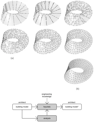
building model heuristic building model* engineering
knowledge
architect architect
Figure 2.1:An architect’s model is modified using an algorithm with embedded engineering knowledge. The grey shade indicates engineer influence in the process.
projects undertaken, the use of heuristic algorithms has been divided into the following 3 categories:
1. Heuristic without external analysis: an algorithm that arrives at a result independently of outside information.
2. Heuristic with consistent external analysis: an algorithm that uses outside information that remains constant.
3. Iterative external analysis: an algorithm that uses changing external information updated at each iteration.
2.2.2. Without External Analysis
Perhaps the simplest use of a computational method is where the engin-eer deploys an algorithm in order to improve a current building model (fig. 2.1). The algorithm used may embed some specialist knowledge or experience in order to produce a desired outcome that is more or less known and expected. The use of a computational approach is beneficial in that outcomes can be reached that go beyond manual methods, due to the iterative power of the computer. Structural form-finding algorithms are a common example of heuristic methods that do not use any external analysis, and were used in multiple case studies during my review period. These algorithms tend to address problems that cannot be solved analytically and require a numerical approach.
Form-finding Minimal Surfaces
Figure 2.2:Finding a minimal surface for the Garden Festival Pavilion
minimal surface geometry and the associated structural benefits for lightweight structures.
The 1972 Munich Olympic Park tensile roofs by Frei Otto and Günther Behnisch are perhaps the most famous examples of lightweight struc-tures with form-found minimal surfaces (Otto & Rasch, 1995). Although such forms were originally found usingnatural computingmethods such
as physical models (in this case soap films), numerical methods using computers are now favoured due to practical considerations such as the ease of boundary condition manipulation and the input/output of data (i.e. node positions).
For the Garden Festival Pavilion [11Gfp], an algorithm was used to find a minimal surface from an initial best guess surface geometry. In the
approach, discrete triangular elements can approximate a continuous surface using the triple-force method(Barnes, 1999; Lewis, 2003) in
com-bination with dynamic relaxation (Day, 1965). The equilibrium solution is found through iteratively applying residual forces until the system converges (fig. 2.2). For this particular project, a Java application was written by the author that imports an initial mesh, finds the minimal surface and then exports the result. The final geometry was then issued to the architect.
Figure 2.3:Laplacian smoothing on the Lusail Bridge Roof
Funicular Form-finding
It is well known to engineers that for structures whose dominant load case is self-weight, a system that works by transferring load using axial forces is more attractive to those that work in bending in terms of minimising material use. The method of finding such forms can be traced back to Robert Hooke who once famously wrote (as an anagram) “As hangs the flexible line, so but inverted will stand the rigid arch” (1675). Antoní Gaudi’s physical hanging chain models (Collins, 1963) have subsequently inspired many architects and engineers to use similar methods in funicular form-finding including Heinz Isler (Chilton, 2000) and Frei Otto (1995). A more detailed literature review of funicular form-finding approaches can be found later in Section 3.2.1, where the subject is addressed in more detail as a main driver behind the design process as opposed to improving existing designs.
Directly replicating the behaviour of physical models in the computer was applied during various case study projects using bespoke Java ap-plications written by the author. This occurred both in two dimensions, for example on the York Way Project [28Yor], and in three dimensions for both the Markham Vale Sculpture [14Mvt] and The KREOD Pavilion [12Kre] (fig. 2.4). For these particular case studies, anexistinggeometric
form was post-rationalised to improve its structural performance. An initial structure supplied by the architect is freed at the nodes (creating fully pinned connections), and subjected to an inverse gravitational load. The resulting large displacements were solved using a relaxation algorithm written by the author (See F.1) that treats bar elements as stiff rigid springs, based on a similar real-time method by Kilian and Ochsendorf (2005). When the gravitational field is reversed, the structure works more efficiently under self-weight than before by increasing axial force and reducing bending moment. For these three case study projects, the resulting geometry was then sent back to the architect for approval.
Form-finding for Fabrication
Figure 2.4:Initial surface form
[image:44.595.169.490.93.316.2]is relaxed on the KREOD pavilion to improve structural behaviour of the final design
Figure 2.5:Architectural concept for The Astana National Library
and construction. The heuristics used were again embedded in the algorithm itself. For example, the distribution of nodes, bars and surface elements to discretise a surface is a common problem in façade design. In this section, form-finding on the projects occurs within a surface embedding space.
On the Astana National Library, [01Anl] my involvement began after the architect had already developed a continually twisting envelope geometry by joining two Möbius strips along their boundaries (fig. 2.5). This created surface geometry that although was ruled (and therefore advantageous for the supporting steelwork), meant the façade surface itself was doubly curved and therefore undevelopable, i.e. it could not be unfolded to the plane without stretching or tearing Flöry & Pottmann (2010). A triangular discretisation was therefore adopted, formed by using the surface ruled lines. This approach however led to every façade panel being a different size and shape (fig. 2.6).
In response, a short discretisation study was undertaken that used a
bottom-uprepulsion based meshing algorithm without a fixed topology.
This approach is described by Turk (1992) in the generation of fair meshes, and was later applied by Kanellos (2007) and Lewis (2011) in generating three-dimensional structures. A particle repulsion method with a fixed topology was used by Williams (2001) when relaxing the triangulated mesh on the British Museum Great Court Roof.
Figure 2.6:Initial Astana National Library façade tiling. Although the base surface is rational, the proposed panels were all a different size and shape changing gradually as they move around the surface.
equal force of repulsion between neighbouring nodes and therefore equal distance. The approach is similar to the annealing of metals, whereby the rate of cooling creates particular atomic spacings and therefore different material properties. The manually defined damping rate must be above a critical value, however this can usually be obtained through visual inspection. This repulsion process is a form of self-organisation, because global order arises out of the local interactions between the nodes which are initially disordered. Figure 2.7 shows one section of the library façade surface, indicating the stages of development with edges connecting nodes neighbouring nodes that are currently influencing each other.
A final triangulated topology is then formed by finding the six nearest neighbours for each node, and removing any edges above a certain cut-off length. Due to the equal distance between nodes, this triangulation has a high proportion of same sized edge lengths and equilateral tri-angles, leading to manufacturing cost savings and reduced complexity during construction. The amount of identical edge lengths for the Astana National Library façade surface shown came to approximately two-thirds of all 600 edges.
In such examples, an optimal solution may exist but in practice, simply being able to achieve a better result than a more direct approach (such
as triangulating using an isocurve grid), can have a large impact. For Astana, the knowledge of what the final geometry meantto the design
team was embedded in the algorithmic approach.
Figure 2.7:Nodal repulsion
[image:46.595.167.492.82.520.2]process on Astana National Library (a) and the final triangulated mesh (b)
Figure 2.8:Algorithm that
incorporates external analysis information
building model heuristic building model*
engineering knowledge
analysis
architect architect
2.2.3. Consistent External Analysis
In the previous section, all of the engineering knowledge behind the approach was embedded in the algorithm itself. However, other methods enable external information such as structural analysis to take place during computation. In this section, some type of external information is required beyond what can be provided by the engineer within the algorithm, with the condition that thisexternal analysisinformation stays
consistent and does not change during an iterative process (fig. 2.8).
Façade Design
Figure 2.9:A freeform doubly curved surface (a) with principal curvature lines found (b) gives PQ mesh of appropriate density (c)
Figure 2.10:Final design for the Senate House glazed roof made from planar quadrilaterals
directions (describing minimum and maximum curvature) leads to them being planar, generating a Planar Quad (PQ) mesh. This planarity and lack of triangular panels give cost benefit in terms of manufacture, especially for glass. In addition to panel planarity, supporting members are torsion free (i.e. no twist along its length) with the additional benefit of members meeting at a common normal, thus improving the connection detail both in terms of cost and complexity (Liuet al., 2006).
The principal curvature field for a freeform surface must be found numerically, and hence an iterative approach is required in order to generate the streamlines of the curvature field that generate the pattern. A generic algorithm that generates the conjugate curve network using surface curvature analysis was written by the author to assist on various case study projects (fig. 2.9).
This approach was used and refined during various projects including National Holdings HQ [06Nhq], London Foyer Sculpture [07Foy], initial work on the KREOD pavilion [12Kre], Tivoli Edge Development [31Tiv] and Senate House Roof [23Shr] (See fig. 2.10). The projects enabled close collaboration between myself and the Ramboll UK Façades team during the initial research period. The cost benefits of planar quadrilateral glass panels as opposed to hot-bent glass is significant. As Mark Pniewski, head of Ramboll UK Façades comments, “the cost difference between flat and doubly curved panels is currently around 8-fold for the same given area” (pers. comm., March 2014).
Figure 2.11:Orchid House
[22Orc]. Initial torsion-free member layout (a) is rationalised through small modifications to the underlying form (b)
the surface geometry produced vastly different outcomes to the final principal curvature field and hence the associated PQ mesh. These modifications revealed a more rational member layout was within reach without large changes to the form. Returning to the architect, we were able to convince them that these modifications to the form should be made.
Here was an example of the building form itself being allowed to be manipulated by the engineer as part of a design exploration process, with the fabrication and structural implications revealed using a com-putational approach. This finding would go on to shape much of the work in Chapter 3, in particular the KREOD pavilion [12Kre] whereby the engineer attempts to get involved earlier in the design processbefore
surface geometries are fixed.
Structural Design
As well as geometric methods which indirectly pursue a particular heur-istic, a computational approach may include integrating an engineering property directly in order to propose an efficient solution. One such example is with the efficient placement of material along the principal stress trajectories of a continuum. This is known to occur in natural systems, such as the distribution of bone material (Meyer, 1867). A more detailed review of the subject is given in Appendix B.
Figure 2.12:Helsinki Central Library competition: conjugate curves following the principal bending stress field
recent work by Kaijima & Michalatos (2007) and Winslow (2009) has investigated discretising freeform surfaces with principal stress grids.
I utilised this structural heuristic on several case study projects. These included The Greenland National Gallery of Art [09Nuk], the Viiki Synergy Building [10Vik] and The Helsinki Central Library competition [26Hcl]. Such structural drivers behind design often gave aesthetically interesting results (fig. 2.12), as well as encouraging the use of exposed concrete soffits often used for passive ventilation in buildings.
Passive Solar Design
As well as structural concerns, some projects during my review invest-igated using passive solar design principles to guide a computational approach. Algorithmic methods for generating architectural surfaces from solar paths have been used by Shepherd (2009) and Turrin et. al. (2010), although there are countless more examples.
Working with the building physics team at Ramboll UK, the Maljevik Bay Resort project [19Mjb] involved generating 30 roof designs for otherwise identical villas that were orientated differently on a hillside. Knowledge of passive solar design was incorporated in sculpting the roof forms for the architect according to the path of the sun both in winter and summer. In winter, sunlight into the building was maximised in order to increase the amount of heat and light generated through natural means. In summer the opposite is desirable. Solar gain and solar glare should be avoided at peak times during the day, hence the roof form should shade the main façade.
Figure 2.13 shows software developed by the author that carved an
Figure 2.13:Java application for generating passive solar roof forms. Ray lines from a glazed façade (a) intersect with an extended roof surface (b). The resulting point cloud forms the new roof surface (c)
Figure 2.14:Maljevik Bay
Villas: roof shapes generated for different orientation angles.
found in Appendix F. The generated roof form could then be exported a CAD file for each unique roof profile. The algorithm works by intersecting sun paths with an initial extended surface mesh (provided by the architect), generating a point each time. Once all the specified months, days and times have been calculated, the resulting point cloud is converted to a revised mesh surface using a constrained 3d convex hull (the constraint avoided large thin triangles). Figure 2.14 shows various roof forms generated at various different orientations on the site.
2.2.4. Incremental External Analysis
In the previous section, all the algorithms developed used some sort of external analysis, however this information was not dependent on the changing state of the model after each iteration. There was no coupling between the model and its environment. In this section, several projects are described where the geometry model is linked directly to any particular analysis so that any change to the model will affect the analysis results (fig. 2.15). Likewise, these analysis results in turn affect changes to the model. In terms of external information to the algorithm and its environment, there exists a feedback loop in the process. This feedback
often gives greater uncertainty in terms of where the process is going and hence the final results are often unexpected.
Structural Geometry Optimisation
building model heuristic building model* engineering
knowledge
analysis architect
building model
[image:51.595.111.455.81.415.2]architect
Figure 2.15:Algorithm using
external analysis updated at each iteration. A cycle between modelling and analysis is now present.
Figure 2.16:Node pushing for a
simply supported beam results in a tied arch
existing node-bar configuration by altering its geometry (not topology). The method I used was similar that described by Kajima and Michalatos for the Land Securities Bridge project (2007), although instead of a constant stress field the structure is analysed at each time step.
The approach works by pushing nodes towards topological neighbours that are the most stressed at that iteration until a cut-off distance is reached (to prevent the merging of nodes). This cut-off distance specifies the maximum density of nodes in the structure. The algorithm written by the author can be found in Appendix F).
An initial test example is shown in fig. 2.16. A simply supported truss under self-weight morphs into a tied arch - a known efficient typology this problem. Rather than suggesting a tied-arch using engineering experience, it is interesting that a bottom-up approach results in an identical solution. As the simple test arrived at a good result that is
validated by engineering experience it suggests that applying the same general heuristic might have benefits for less trivial problems.
Figure 2.17:Nodal displacements difference between original and optimised on Astana National Library.
-6 -5 -4 -3 -2 -1 0 1 2
1 501 1001 1501 2001 2501 3001 3501 4001
Node reference
Δ
Defle
ction (mm
)
algorithm and exported the updated location information. By retaining the same topology as the original model, only the xyz coordinates needed to be updated.
For the project, the total façade area was over 20,000m2, with a total of
approximately 4500 nodes. The node pushing algorithm was used which deformed the regular façade structure as proposed by the architect to a more irregular panelling system. The façade remained constrained by the doubly curved surface geometry that could not be altered. By using this approach, we were able to reduce the total nodal displacement of the structure under permanent loads by approximately 5% after only 100 iterations. Although some nodes actually decreased in performance (see fig. 2.17), the overall result was favourable. Following this critical point, the total performance (measured using the inverse of the total deflection) began to drop off as the lengths of the members between the nodes increased.
The final resulting geometry can be seen in fig. 2.18. Whilst improve-ments could be made structurally, the increasingly irregular pattern came at a cost to the fabrication efficiency. The façade panel sizes varied con-siderably more after the structural optimisation and a subsequent design review meant that the new geometry proved too costly to implement, regardless of the structural improvement. This wasn’t a failure in terms of the algorithmper se, but rather the reality that when applying a single
heuristic method such aspushing nodes to high stress, they do not easily
allow for any other performance objectives to be included. This was the opposite problem with the node repulsion algorithm, whereby structural concerns became secondary to fabrication efficiency. As more objectives and constraints are included, the more complex the algorithm becomes.
Structural Topology Optimisation
Figure 2.19:Topology Optimisation Experiment using the Homogenization method on Tallinn Town Hall
in Section 2.2.3, TO aims to find the optimal material usage for a given structural problem, achieved using an iterative method.
TO approaches generally fall into