and sharing with colleagues.
Other uses, including reproduction and distribution, or selling or
licensing copies, or posting to personal, institutional or third party
websites are prohibited.
In most cases authors are permitted to post their version of the
article (e.g. in Word or Tex form) to their personal website or
institutional repository. Authors requiring further information
regarding Elsevier’s archiving and manuscript policies are
encouraged to visit:
Contents lists available atScienceDirect
BioSystems
j o u r n a l h o m e p a g e :w w w . e l s e v i e r . c o m / l o c a t e / b i o s y s t e m s
Towards
Physarum
binary adders
Jeff Jones
∗, Andrew Adamatzky
Unconventional Computing Centre, University of the West of England, Coldharbour Lane, Bristol BS16 1QY, United Kingdom
a r t i c l e i n f o
Article history:
Received 16 February 2010
Received in revised form 11 April 2010 Accepted 13 April 2010
Keywords:
Nonlinear dynamical systems Logical gate
Physarum polycephalum Chemical computers Biological computers
a b s t r a c t
Plasmodium ofPhysarum polycephalumis a single cell visible by unaided eye. The plasmodium’s foraging behaviour is interpreted in terms of computation. Input data is a configuration of nutrients, result of computation is a network of plasmodium’s cytoplasmic tubes spanning sources of nutrients.Tsuda et al. (2004)experimentally demonstrated that basic logical gates can be implemented in foraging behaviour of the plasmodium. We simplify the original designs of the gates and show – in computer models – that the plasmodium is capable for computation of two-input two-output gatex,y → xy,x+yand three-input two-outputx, y, z →
xyz, x¯ +y+z. We assemble the gates in a binary one-bit adder and demonstrate validity of the design using computer simulation.© 2010 Elsevier Ireland Ltd. All rights reserved.
1. Introduction
A plasmodium is a vegetative state of acellular slime mould
Physarum polycephalum. The plasmodium feeds on microscopic food particles, including microbial life forms. The plasmodium placed in an environment with distributed nutrients develops a network of protoplasmic tubes spanning the nutrients’ sources. The topology of the plasmodium’s protoplasmic network optimizes the plasmodium’s harvesting on the scattered sources of nutrients and makes more efficient flow and transport of intra-cellular compo-nents (Nakagaki et al., 2000; Nakagaki, 2001; Nakagaki et al., 2001, 2007).
The plasmodium is capable for approximation of shortest path (Nakagaki et al., 2001), computation of planar proximity graphs (Adamatzky, 2008) and plane tessellations (Shirakawa et al., 2009), primitive memory (Saigusa et al., 2008), basic logical computing (Tsuda et al., 2004), and control of robot naviga-tion (Tsuda et al., 2007). The plasmodium can be considered as a general-purpose computer because the plasmodium simu-lates Kolmogorov–Uspenskii machine—the storage modification machine operating on a colored set of graph nodes (Adamatzky, 2007).
The paper is structured as follows. In Section2we introduce the experimental gates invented inTsuda et al. (2004)and re-interpret the gates as multi-output logical gates. We analyse asynchronism and reversibility of the gates in Sections3 and 4. We simulate the gates in a particle-swarm model in Section5. We assemble the
∗Corresponding author.
E-mail address:[email protected](J. Jones).
gates in the one-bit half-adder and simulate the adder’s behaviour in Section6.
2. PhysarumGates
Physarumgates constructed inTsuda et al. (2004)were made of agar gel channels. Presence of a plasmodium in an input channel represents logical input Truth (‘1’) and absence of plasmodium—logical input False (’0’). Values of signal in out-put channels are encoded similarly. Sources of chemoattractants (glucose) are placed near exits of output channels. The chemoat-tractants diffusing in the agar gel channels establish gradients which guide the plasmodia towards closest sources of attrac-tants.
In experiments discussed inTsuda et al. (2004)plasmodia inoc-ulated in different input channels exhibited an aversion towards each other. They did not merge. If propagating plasmodium p1 encountered another plasmodiump2 in a channelp1 wanted to travel in the plasmodium p1 chosen another route of propaga-tion. The fact that two ‘colliding’ plasmodia do not merge was also supported by our experiments on constructing Voronoi diagram by plasmodia inoculated on nutrient-rich agar (Adamatzky, 2008; Shirakawa et al., 2009). Approaching wave fronts of growing plas-modia usually ‘freeze’ for an up 16 h, when collide, however later the fronts merge. Outcomes of interaction between two localized (i.e. propagating as wave-fragments) plasmodia depends on many factors, and ‘elastic’ collision is just one amongst many scenarios of the plasmodia interactions.
In the paper byTsuda et al. (2004)some output channels of
Physarum gates were considered as buffers. Let us now slightly redesign the gates (Tsuda et al., 2004) and interpret all outputs of the gates as Boolean logic values.
0303-2647/$ – see front matter© 2010 Elsevier Ireland Ltd. All rights reserved.
52 J. Jones, A. Adamatzky / BioSystems101 (2010) 51–58
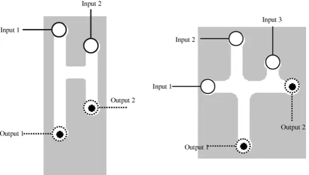
Fig. 1.Scheme ofG1gate: (a) landmark points are shown; configuration of plasmodia in gates for all combinations of input values—x= 0,y= 0 (b),x= 0,y= 1 (c),x= 1,y= 0 (d),x= 1,y= 1 (e), the plasmodia bodies are shown by thick lines; (f) input–output logical function realized by the gate. Chemoattractants are placed in sites marked by solid black discs.
ConsiderG1gate inFig. 1a. Physical structure of the gate satis-fies the following constraints|xb|=|yc|and|bd|>|bc|+|ce|(Fig. 1a). Chemoattractants are placed in sitesdande. We assume strength of attraction tod(e) at pointpis proportional to distance|pd|(|pe|) (Fig. 1a).
Situations corresponding to input values (0,0), (0,1) and (1,0) are simple. When no plasmodia are inoculated inxandynothing appears at outputsdande(Fig. 1b). When plasmodium is placed only in siteythe plasmodium follows the route (yc)(ce) (Fig. 1c). If plasmodium inoculated only in sitexthe plasmodium follows the route (xb)(bc)(ce) (Fig. 1d).
The main trick of the gate is in how input valuesx= 1 andy= 1 are handled. The plasmodia are inoculated in sitesxandy(Fig. 1d). The plasmodium growing from siteyfollows route (yc)(ce). The plasmodium growing from sitextends to follow route (xb)(bc)(ce), however part of the route (ce) is already occupied by another plas-modium. Therefore the plasmodium, starting inx, grows along the route (xb)(bd) (Fig. 1d).
A table of transformationx,y → d,eshows that the gateG1 (Fig. 1f) implements logical conjunction and logical disjunctionsx,
y → xy,x+yat the same time but on two different outputs.
Geometrical structure ofG2gate is shown inFig. 2. Chemoattrac-tants are placed in sitescanddand plasmodia can be inoculated in sitesx,yandz(Fig. 2a). Lengths of channels in the gate sat-isfy the following conditions: |xc|<|xd|,|ac|<|ad|,|bc|<|bd|, and
|zb|+|bc|<|ya|+|ac|.
In Tsuda et al. (2004) input channelsyand z(Fig. 2a) were assigned to constant Truthinputs an output channel c to a buffer (unused output to collect ‘excess’ of plasmodium). Let consider sce-nario when all three input can take values ‘0’ and ‘1’ and both outputs have a meaning.
If plasmodium placed in sitezit propagates towards closest attractant-site c(Fig. 2c); similarly a plasmodium inoculated in siteypropagates towards attractant-sitec(Fig. 2d). When plas-modia are placed in sitesyandzsimultaneously, the plasmodium from the site z follows the route (zb)(bc) and thus blocks the way for plasmodium propagating fromy(Fig. 2e). Therefore the plasmodium originating in y moves to attractant-sited(Fig. 2e). The situations sketched inFig. 2g–j can be described similarly. Considering the transformationsx,y → c, d we find that the gate implements the following logical function x, y →
x, xy¯. Ify- andz-iputs are constant Truth,y= 1 andz= 1, the gateG2Fig. 3.Scheme ofPhysarumone-bit half-adder. Input variables arexandy,1on input channels represent constant Truth. Carry valuexyand sumx⊗yare highlighted by dotted rectangle, unused outputsx+y,1and (¬x)(¬y) by dotted ellipses.
is a negation (this how it was initially designed inTsuda et al., 2004).
PhysarumgatesG1 andG2 can be cascaded by linking output gel channels of one gate to input gel channels of another gate. An example of such cascading in a form of one-bit half-adder is shown inFig. 3. Four pieces of plasmodium are fed in input channels as constant Truth. The plasmodia representing Boolean variablesx
andyare multiplied or branched and fed into gateG1and two copies of gateG2. Output channels of gatesG2are fed into data channels of another gateG1. In addition to results we are looking for –xy andx⊕y– the circuit (Fig. 3) produces several byproducts:x+y, (¬x)(¬y) and two copies of constants Truth. These signals can be used further down in the chain of computation or routed in the buffer zones (plasmodium pool). Plasmodia representing constant Truthcan be also rerouted back to control inputs of gatesG2.
3. Asynchronism
Synchronization of signals is amongst key factors in proper func-tioning of logical circuits. Architecture ofPhysarumgates allow for a certain degree of asynchronism. Let us evaluate a degree of asynchronism of gatesG1andG2.
Assume outputs of gateG1are read inw≥ |xb| + |bc| + |bd|time units after on the plasmodia entered its data channel. Let plas-modia representing logical variablesxandyenter their channels at time stepsxandy. Letx= 1 andy= 1. Thenx-plasmodium must
reach sitecof gateG1 (Fig. 1a) after the sitecis occupied byy -plasmodium. That isx+|xb| ≥y+|yc|. Due to|xb|=|yc|(Fig. 1a) we
havex≥yIfx= 1 thex-plasmodium must reach exit of the output
channel (xd) before ‘signal reading’ time-window closed. There-fore we havey≤x≤˛1=w− |xd| + |bc|. The parameter˛1is a degree of asynchronism of gateG1. In the same manner we obtain a constraint on timingx,yandzof signalsx,yandzin gateG2:
z≤y≤x≤w− |ya| − |ad|. Thus, degree of asynchronism of gate G2is˛2=w− |ya| − |ad|.
Architectures of Physarum gates G2 (Fig. 2) and G1 (Fig. 1) assume gradients of chemoattractants from output sites (where sources of attractants) are placed to input sites (solid black discs
Fig. 4.Gates ¯G1(a and b) and ¯G2(c and d). Landmarks are shown in (a) and (c), the gates functional schemes in (b) and (d). Inputs are marked with circles, outputs with solid discs. Chemoattractants are placed in sites marked by solid black discs.
inFigs. 2 and 1). What will happen if we reverse the gradients and place sources of chemoattractants in input sites of original gates and consider output sites of original gates as inputs of new gates (Fig. 4)? We will write gatesG1andG2with reversed gradients and input–output as ¯G1and ¯G2.
4. Outcomes of Reversing Gradients of Chemoattractants
Let us consider gate ¯G1. If plasmodium placed in sited(Fig. 4a) it propagates towards siteb(because it is the only choice) and then follows gradients towards closest source of chemoattractants, site
x. Plasmodium inoculated in siteetravels along the route (ec)(cy). Two plasmodium placed in sitesdandesimultaneously, do not interact. This shows that gate ¯G1:x, y → x, yacts as a simple conductor of signals when polarity of chemoattractant gradients is reversed (Fig. 4b).
In gate ¯G2 plasmodium placed in site c always propagates towards closest source of attractants, sitez. Plasmodium placed in sitexif|xa|>|zb|but the plasmodium propagates to sitezif|xa|>|zb|
(Fig. 4c). The plasmodium placed incand/ordnever reaches site
y, therefore output marked ‘y’ is always ‘0’. Analysis of all com-binations of input signals demonstrate that for|xa|>|zb|we have
¯
G2:x, y → x, y, and for|xa|>|zb|we have ¯G2:x, y → xy, x+y (Fig. 4d).
In summary, when gradients of chemoattractants and input–output swapped in gatesG1andG2the gateG1becomes a simple conductor and the gateG2becomes gateG1.
5. Computational Modelling ofPhysarumGate Behaviours
To model thePhysarumgate behaviours the three physical crite-ria identified inTsuda et al. (2004)and utilised in the design of the logic gates need to be implemented. The criteria can be summarised as follows:
1.Physarumgrows and moves towards nutrient chemoattractant gradients.
2. If two plasmodium fragments encounter each other, they will avoid contact where other routes exist.
3. If two plasmodium fragments cannot avoid contact, the plas-modia will fuse.
54 J. Jones, A. Adamatzky / BioSystems101 (2010) 51–58
Activation Long-range Inhibition) reaction-diffusion pattern for-mation processes and exhibits a complex range of patterning by varying particle sensory parameters (Jones, 2010b). We assume that each particle in the collective represents a hypothetical unit ofPhysarumplasmodium gel/sol interaction which includes the effect of chemoattractant gradients on the plasmodium membrane (sensory behaviour) and the flow of protoplasmic sol within the plasmodium (motor behaviour). The summation of particle posi-tions corresponds to a static snapshot of network structure whilst the collective movement of the particles in the network corre-sponds to protoplasmic flow within the network.
Although the model is very simple in its assumptions and imple-mentation it is capable of reproducing some of the spontaneous network formation, network foraging, oscillatory behaviour, bi-directional shuttle streaming, and network adaptation seen in
Physarum, using only simple, local functionality to generate the emergent behaviours. Details of the particle morphology, sensory and motor behavioural algorithms can be found inJones (2009b)
and in this paper we use an extension of the basic model (without utilising oscillatory behaviour) to include plasmodium growth and adaptation (growth and shrinkage of the collective).
The environment is represented by a greyscale image where dif-ferent values correspond to difdif-ferent environmental features (for example, habitable areas, inhabitable areas, nutrient sources). The particles move about their environment (a two-dimensional lat-tice) and sample sensory chemoattractant data from an isomorphic diffusion map. When particles move about their environment they deposit chemoattractant to the same structure. Chemoattractant gradients were represented by projection of chemoattractant to the diffusion map at the locations indicated on the gate schematic illustrations. The projection weight was set at 20 multiplied by the chemoattractant pixel value (255). The weight factor is high as chemoattractant is deemed to be completely absorbed when it encounters the edges of the chamber and a large weight value is necessary to ensure the required propagation distance. The diffu-sion kernel was a 7×7 window for all experiments. Diffusion was achieved by the mean of the local window at each location in the dif-fusion map and damped at 10−4(i.e. new value is equal to the mean multiplied by 1–10−4). We assumed that diffusion of chemoattrac-tant from a nutrient source was suppressed when the source was engulfed by particles. The suppression was implemented by check-ing each pixel of the food source and reduccheck-ing the projection value (concentration of chemoattractants) by multiplying it by 10−3 if there was a particle within a 9×9 neighbourhood surrounding the pixel. Particle sensor offset was 5 pixels, angle of rotation set to 45◦, and sensor angle was 45◦.
Growth and adaptation of the particle model population is currently implemented using a simple method based upon local measures of space availability (growth) and overcrowding (adap-tation, or shrinkage, by population reduction). This is undoubtedly a gross simplification of the complex factors involved in growth and adaptation of the real organism (such as metabolic influences, nutrient concentration, waste concentration, slime capsule cov-erage, and bacterial contamination). However the simplification renders the population growth and adaptation more computation-ally tractable and the specific parameters governing growth and shrinkage are at least loosely based upon real environmental con-straints of space and nutrient availability. Growth and shrinkage states are iterated separately for each particle and the results for each particle are indicated by tagging Boolean values to the par-ticles. The growth and shrinkage tests were executed every three scheduler steps and the method employed is specified as follows. If there are 1–10 particles in a 9×9 neighbourhood of a particle, and the particle has moved forwards successfully, the particle attempts to divide into two (i.e. a new particle is created) if there is an empty location in the immediate neighbourhood surrounding the particle.
If there are 0–20 particles in a 5×5 neighbourhood of a particle the particle survives, otherwise it is annihilated.
5.1. Modelling Individual Gates
To implement the gates using the model, the schematic illus-trations in Figs. 1 and 2 were transformed into the spatial representations shown inFig. 5. The spatial pattern and greyscale encoding (boundaries, nutrient sources) is used to configure the diffusive map.
Particles were introduced (depending on logical input condi-tions) at the areas indicated by solid circles at the top of the gates. Strong sources of chemoattractant were introduced at the outputs indicated as enclosed by dashed circles. The chemoattractant dif-fused from the output locations along channels etched into the gate configurations (white areas) and chemoattractant was removed immediately on contact with boundaries of the channels (light grey areas). The particle population was inoculated at identical times at the inputs, sensing, growing and moving towards the propagating diffusion gradients. To ‘anchor’ the growing paths to the start posi-tions a very small amount of chemoattractant was also deposited at the respective start positions (the amount chosen was the lowest level needed to anchor the position without affecting the actual gate computation). Population inoculation and chemoattractant diffu-sion occurred at the same time and there was little or no directed growth of the population until the chemoattractants reached the source of inoculation.
The operation of the gates occurs due to the complex inter-actions between the chemoattractant diffusion gradients. Because there is a quantitative aspect to the chemoattractant gradient (i.e. particles sense not only the presence but also the strength of the diffusion), the gradient concentration is affected by the length and width of the gate channels (Jones, 2009a). The point at which the competing wave fronts meet is a spatial interface which delin-eates path choices in a similar way to those observed in chemical reaction-diffusion computations (Steinbock et al., 1995). Thus, the environment is partially responsible for the initial selection of path choice. This ‘background processing’ by the environment satisfies the first of the three aforementioned criteria for plasmodium gate construction.
Two more factors add to the complexity of gradient interac-tions: Firstly when the particle representation of the plasmodium engulfs a food source, the diffusion of chemoattractant from that source is suppressed (reduced by a factor of one thousand). This alters the strength of the gradient field from the engulfed source and the interface position where competing fronts meet shifts to reflect the new gradient field. Secondly, the collective movement of the particle population also results in local chemoattractant depo-sition along the path (this depodepo-sition is responsible for the local recruitment of particles by positive feedback and also acts to main-tain the cohesiveness of the particle swarm). The local deposition of chemoattractant is also subject to the same diffusion as that which affects the food sources (in fact it is represented computationally as the same ‘substance’) and the diffusion away from the particle pop-ulation also acts to generate a dynamical interface which competes with the food source gradients.
gra-Fig. 5.Spatial implementation of logic gatesG1andG2used in the particle model.
dients or a combination of both swarm and food gradients. The third criterion—fusion of plasmodia—can be represented in the par-ticle model when movement of separate parpar-ticle paths is limited and perturbation of the dynamic boundary occurs. This can result in fusion of network paths which corresponds to fusion of plas-modia.
The complex evolution of gradient fields can be seen in an exam-ple run ofG2 with the inputs 0 1 1 inFig. 6. The top row shows the particle positions and the bottom row shows the chemoattrac-tant gradient field enhanced by a local method of dynamic contrast enhancement. The first column shows the propagation of chemoat-tractant gradient from the two food sources and the interfacial region (dashed arcs). Note that the gradient from the right sup-presses the gradient from the bottom source. The second column shows the effect of suppression of the rightmost food source when engulfed by the particle population which has migrated towards it. Because the bottom food source is not suppressed the gradient from this source is stronger than the right side and the interface boundary shifts to the right of the T-junction. Note that there is also a weaker interface boundary between the diffusion gradient emanating from the bottom food source and the chemoattractant deposition from the particle population in the long vertical column. The third column shows the result of the competition between the food gradient and the population gradient—the food gradient is stronger and the population grows and migrates downwards to the food node.
When the bottom node is suppressed the two separate paths remain stable and do not fuse. A fragile interfacial boundary can be seen between the two network paths (dashed arc) and, as long as the particles do not cross the ‘buffer’ space between the two paths, the paths will not fuse.
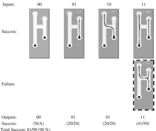
Results using the particle model for gatesG1andG2are shown inFigs. 7 and 8. TheG1 gate achieved 90% reliability and theG2 gate achieved 98.57% reliability. The input conditions 0–0 were not included with the results because the output result for these inputs is guaranteed regardless of gate design. For theG1gate we see that the shorter path to the right food source attracts the simulated plas-modium in both 0–1 and 1–0 condition. Note that no branching occurs from the plasmodium to the left nutrient source when the right source is connected. This is because the movement of particles (and their deposition to the diffusion map) creates a local diffusion field around the particle collective. The strength of this locally gen-erated field is enough to suppress the field emanating from the left food source and no branching is observed. If the strength of the local field were less than that of the nutrient source then branching and growth to the left nutrient source would indeed occur.
The errors in theG1 gate all occurred in the 1–1 input condi-tion. The ‘pattern’ of the error is that the left particle stream did not continue downwards to the food source, but fused with the right side particle stream (indicated by dashed box). Analysis of all of the results found that whenever the growing particle plasmod-ium encountered a junction in a gate an apparent ‘hesitation’ was seen. The growth tip appeared to be indecisive as to which direc-tion to take. When a direcdirec-tion was eventually chosen the growth speed increased when the growth tip moved past the junction. The hesitation, and indeed some of the gate errors, was caused by disturbances in the diffusion field near the tip of the growing plasmodium. The diffusion gradient emanating from the nutrient sources is relatively uniform whereas the gradient from the plas-modium tip is more intermittent in quality (because the tip growth is non uniform and changeable in form). In contrast the gradient from a moving straight part of the particle plasmodium was more uniform. The fragility of the gradient field at the growth tip was further perturbed by the spatial changes in the environment at the junctions. This, coupled with increased possible choices of direc-tions, led to what we describe as junctional errors. The junctional errors are characterised by failures in searching of the growing plas-modium tip and were responsible for all of the failure instances of theG1gate.
TheG2gate, although more complex in design, was more reliable thanG1and the only errors which occurred were a single junctional error in the 0 1 1 input condition and an error in the 1 1 1 input condition. This error was classed as a timing error and was caused by different growth rates from the two left-side inputs. Ideally the two particle streams should meet and fuse but differences in the growth of the two separate streams led to non fusion and errors in output.
To illustrate the transient dynamical nature of growth tip hes-itation at junctions, junctional and timing errors, please refer to the supplementary video recordings at: http://uncomp.uwe. ac.uk/jeff/gates.htm.
6. Modelling the Half-adder
[image:6.595.147.462.79.257.2]posi-56 J. Jones, A. Adamatzky / BioSystems101 (2010) 51–58
Fig. 6.Evolution of ‘plasmodium’ positions and interaction fronts in the particle model for theG2gate with inputs 0 1 1. Top row: particle positions. Bottom row: chemoattrac-tant gradient. Arrows indicate propagation of gradient from food sources. Dashed arcs represent boundary regions separating competing gradients. Dashed circles represent diffusion from food sources suppressed by engulfment. See text for explanation.
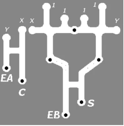
tions of the lower gate synthetic chemoattractant stimuli (small dots) were placed to guide any plasmodium along the channel to the input positions. The ‘G2G2G1’ triplet combination acted as the XOR (summation) part of the half-adder. The and section of the half-adder (carry computation) was implemented as a single
G1 gate (Fig. 9, left). In the simulations the branching of initialX andYsignals to provide the inputs to both sections of the half-adder was not implemented in an effort to simplify the design and the relevantXandYinputs were introduced to the gate manu-ally.
[image:7.595.134.453.484.750.2]Fig. 8.Summary of results for particle approximation ofPhysarum-based logic gateG2.
Fig. 9.Spatial representation of half-adder based on combinations ofG1andG2.X andY: inputs to half-adder, 1: constant Truthsignals, S: sum output, and C: carry output. Solid discs are food sources and small dots are small food sources to feed outputs towards lower gate inputs. EA and EB: error checking flags (see text).
The use of constant Truthinputs to the half-adder introduces errors in gate output when inputs are 0–0. This is because the out-ermost truth signals at the inputs of theG2G2 gates travel down through the gates and into the lowerG1gate. This would result in the ‘no input’ condition actually causing an erroneous output. Apart
from redesigning the gate this presents an opportunity to consider possible use of error checking signals in the gate design. One pos-sible error checking signal is the ‘EA’ output in the left side of the circuit (Fig. 9, left). It can be seen that this flag should be set when-ever any of the inputs are set to true. It would therefore be possible to use the absence of the EA output to indicate a 0–0 input to the half-adder, and thus indicate erroneous output from the constant Truthinputs toG2G2. Another possible use of outputs to indicate error conditions is the ‘EB’ output from the leftG1portion of the
G2G2G1triplet (Fig. 9, bottom). It can be seen (Fig. 10) that the EB flag should never be set unless the 0–0 condition caused by con-stant Truthinputs occurs. This flag could be combined with the lack of EA output to indicate errors. When the EB flag is set without the presence of EA then a fault can be assumed to have occurred within the half-adderG2G2G1triplet. Of course the addition paths and mechanisms to make use of these error checking flags adds another layer of complexity to the circuitry which is out of the scope for this paper. The results of the half-adder approximation can be seen inFig. 10.
The failure rate for the half-adder approximation, even when not including the difficulty posed by the 0–0 configuration, was signif-icantly higher than for the single gates. The majority of the failures were caused by timing errors, which occurred when the outermost inputs to theG2G2combined gate did not fuse correctly with the constant Truthinputs and, instead, travelled down towards the lower gate. Junctional errors also occurred three times in the left
G1gate for the 1–1 input condition.
The combination and extension of the individual gates appeared to compound the errors in the individual gates. Although no defini-tive answer can be given as to why the unreliability increased,
[image:8.595.122.485.613.750.2]58 J. Jones, A. Adamatzky / BioSystems101 (2010) 51–58
we speculate that the combining of the gates subtly affected the propagation and profile of the chemoattractant gradients.
7. Discussion
The results from the computational approximation ofPhysarum
support the findings ofTsuda et al. (2004)that the organism can be used to construct simple logic gates, and also the computing schemes within this paper which explored the creation of more complex combined gates and half-adder circuitry. The findings sug-gest that, although such circuits can indeed be built, the presence of both timing errors and junctional (search) errors would severely limit the effectiveness and practicality with even more complex circuits.
The matter of errors of the gate operations (timing errors and junctional errors) requires further consideration. The term ‘error’ depends on the perspective taken. From an experimental viewpoint the occasionally unreliable operation of the gates is erroneous. But the notion of externally applied – by the experimenter – environ-ment conditions and metrics of success cannot be easily applied to the behaviour of a living (or even simulated) collective organ-ism, whose sole imperative is the location and connection of food sources for survival. By following the biological imperative the organism is not actually doing anything ‘wrong’.
Ascribing such obviously successful survival strategies as erroneous behaviour merely because they do not suit the exper-imenter’s demands seems to do a disservice to the organism. At the risk of further anthropomorphism it seems as if the collective is hampered by adouble-bindcaused by conflicting biological and computational requirements: “Please forage successfully, but not too successfully”.
It appears that this conflict could not easily be resolved from an engineering perspective because, on the one hand, we cannot lessen the requirements of digital circuit operation to accept log-ically incorrect output. Nor is it possible to reign-in the natural foraging ability of the plasmodium. Although it is possible to track the logical errors by using spare signal channels (as noted in the half-adder circuit), acknowledging that there is an internal problem does not actually rectify the problem. Simple logic gates form the basis of complex circuits whose reliability must be total so that they may be considered as ‘black box’ interchangeable components in hardware design. They are designed from the ‘top-down’ to achieve their reliability and unpredictable or emergent results cannot be tolerated using this design approach.Physarum-based computing uses the opposite approach—simple low-level interactions gener-ate complex and unpredictable emergent computing abilities from the ‘bottom-up’. Although we cannot guarantee the low-level relia-bility of the output of foraging in thePhysarumplasmodium wecan
state that the plasmodium will forage and that the resultant emer-gent behaviour will be complex and unpredictable. Harnessing this spatial and temporal unpredictability, for example in a manner as suggested byAono et al. (2009), may prove to be a more suitable application of the computational properties ofPhysarum.
Although the use ofPhysarumfor classical logical gates indeed makes use of its intrinsic properties (gradient oriented growth,
avoidance, fusion), the confinement of this naturally amorphous, dynamic and flexible organism into architectures which require precise timing and predictable path traversal does not utilise the natural advantages which the organism possesses. The increasing failure rate when circuit complexity is scaled upwards may – per-haps fancifully – be interpreted as the embodiment of an internal frustration by the plasmodium at such confinement and control. It appears likely thatPhysarummay be more naturally suited to device implementations which harness its abilities in integrating complex, noisy, unpredictable, spatial and temporal signals. In such devices the concept of rigid control of behaviour will be reduced to an influence on behaviour, where the influence is applied as a +ve or−ve stimuli which affects behaviour. Suggested lines of inquiry lie in pattern recognition, signal generators (oscillators), signal fil-tration and memory storage. We plan to investigate such devices in a further study.
Acknowledgment
This research is funded by the Leverhulme Trust project F/00577/I “Mould intelligence: biological amorphous robots”.
References
Adamatzky, A., 2007. Physarum machine: implementation of a Kolmogorov–Uspensky machine on a biological substrate. Parallel Process. Lett. 170, 455–467.
Adamatzky, A., 2008. Developing proximity graphs byPhysarum polycephalum: does the plasmodium follow Toussaint hierarchy? Parallel Process. Lett. 19, 105–127. Aono, M., Hirata, Y., Hara, M., Aihara, K., 2009. Amoeba-based chaotic neurocomput-ing: combinatorial optimization by coupled biological oscillators. New Generat. Comput. 27, 129–157.
Jones, J., 2009a. Passive vs active approaches in particle approximations of reaction-diffusion computing. Int. J. Nanotechnol. Mol. Comput. 1 (3), 37–63.
Jones, J., 2009b. Approximating the Behaviours ofPhysarum polycephalumfor the Construction and Minimisation of Synthetic Transport Networks, Unconven-tional Computation 2009, LNCS 5715. Springer, pp. 191–208.
Jones, J., 2010a. The emergence and dynamical evolution of complex transport net-works from simple low-level behaviours. Int. J. Unconventional Comput. 6 (2), 125–144.
Jones, J., 2010b. Characteristics of pattern formation and evolution in approxima-tions ofPhysarumtransport networks. Artif. Life 16 (2), 127–153.
Nakagaki, T., 2001. Smart behavior of true slime mold in a labyrinth. Res. Microbiol. 152, 767–770.
Nakagaki, T., Yamada, H., Toth, A., 2001. Path finding by tube morphogenesis in an amoeboid organism. Biophys. Chem. 92, 47–52.
Nakagaki, T., Iima, M., Ueda, T., Nishiura, y., Saigusa, T., Tero, A., Kobayashi, R., Showalter, K., 2007. Minimum-risk path finding by an adaptive amoeba network. Phys. Rev. Lett. 99, 068104.
Nakagaki, T., Yamada, H., Ueda, T., 2000. Interaction between cell shape and con-traction pattern in thePhysarum plasmodium. Biophys. Chem. 84, 195–204. Saigusa, T., Tero, A., Nakagaki, T., Kuramoto, Y., 2008. Amoebae anticipate periodic
events. Phys. Rev. Lett. 100, 018101.
Shirakawa, T., Adamatzky, A., Gunji, Y.-P., Miyake, Y., 2009. On simultaneous construction of Voronoi diagram and Delaunay triangulation byPhysarum poly-cephalum. Int. J. Bifurcat. Chaos 19, 3109–3117.
Steinbock, O., Toth, A., Showalter, K., 1995. Navigating complex labyrinths: optimal paths from chemical waves. Science 267, 868–871.
Tsuda, S., Aono, M., Gunji, Y.-P., 2004. Robust and emergentPhysarum logical-computing. Biosystems 73, 45–55.