ORGANOTIN ACENAPHTHENE COMPOUNDS
Kasun S. Athukorala Arachchige
A Thesis Submitted for the Degree of PhD
at the
University of St Andrews
2014
Full metadata for this item is available in
St Andrews Research Repository
at:
http://research-repository.st-andrews.ac.uk/
Please use this identifier to cite or link to this item:
http://hdl.handle.net/10023/6363
Synthesis and Crystallographic Studies of Novel
Organotin Acenaphthene Compounds
by
Kasun S. Athukorala Arachchige
Thesis submitted in partial fulfilment for the degree of
Doctor of Philosophy
The University of St Andrews
April 2014
Declaration
I, Kasun S. Athukorala Arachchige, hereby certify that this thesis, which is approximately 31, 800 words in length, has been written by me, and that it is the record of work carried out by me or principally by myself in collaboration with others as acknowledged, and that it has not been submitted in any previous application for a higher degree.
I was admitted as a research student in September 2010 and as a candidate for the degree of Ph.D. in August 2011; the higher study for which this is a record was carried out in the University of St Andrews between 2010 and 2014.
Date …...…... Signature of Candidate …...…...
I hereby certify that the candidate has fulfilled the conditions of the Resolution and Regulations appropriate for the degree of Ph.D. in the University of St Andrews and that the candidate is qualified to submit this thesis in application for that degree.
In submitting this thesis to the University of St Andrews I understand that I am giving permission for it to be made available for use in accordance with the regulations of the University Library for the time being in force, subject to any copyright vested in the work not being affected thereby. I also understand that the title and the abstract will be published, and that a copy of the work may be made and supplied to any bona fide library or research worker, that my thesis will be electronically accessible for personal or research use unless exempt by award of an embargo as requested below, and that the library has the right to migrate my thesis into new electronic forms as required to ensure continued access to the thesis. I have obtained any third-party copyright permissions that may be required in order to allow such access and migration, or have requested the appropriate embargo below.
The following is an agreed request by candidate and supervisor regarding the electronic publication of this thesis:
Embargo on both all of printed copy and electronic copy for a period of two years on the following grounds:
Publication would preclude future publication
Date …...…... Signature of Candidate …...…...
Acknowledgements
The past 3 years of my academic life in St Andrews have been full of adventures and new challenges. I have faced the most difficult period in my life during my studies in St Andrews. During this time of difficulty, my supervisors, friends and university staff have been most helpful in helping me to overcome so many hurdles and I am ever grateful to them for their enormous help and support.
First of all I would like to thank my supervisor Professor Alex Slawin, who has given me her full support and encouragement during my PhD. Also Professor Derek Woollins, who has guided me throughout my time in St Andrews, shadowing my studies and leading me through my PhD work to make me who I am today. Thank you so much to both of you for your enormous support and I am ever in debt to both of you.
My biggest thanks go to Dr Fergus Knight; my Post Doc who helped me a lot during my personal difficulties and his support, encouragement and proof reading skills have been most helpful in allowing me to complete my work on time. Many thanks should also go to Dr Katie for the support given to me during my stay in St Andrews. Also, Louise who started her PhD at the same time as me has helped me a lot during my time in St Andrews and with formatting this thesis.
I must also thank my research group friends, Andreas, Brain C, Jackie, Matthew, Paula, Lawrence and all the members of the Woollins and Kilian group, for your help and fun filled company over the past 3 years. They have given me so many crystals to run and it has helped me solve new structures which in turn has helped me to grow my crystallography knowledge much wider every day.
I would like to take this opportunity to give thanks to St Andrews University Chaplin, Donald MacEwan and Rob Warren who have helped me to find university accommodation during my difficult time in St Andrews. Also I would like to thank all the university accommodation, student service and chemistry staff members for your understanding and generosity during my time in St Andrews.
My thanks also goes to all my Sri Lankan friends in UK and Sri Lanka they have been really helpful to overcome the difficult time. Special thanks also go to Wellawaththe Seelagawesee Thero, Rewatha Thero, Upulani, Kushan, Chamila, Madu, Pradeep, Kannan, Geetha, Yasith, Sachith, Anusha, Rani and David for looking after me during my time in St Andrews.
I would like to thank each and everybody who has given me any kind of help and support for me to come this far in my academic life.
Collaboration statement with regards to the Chapter 3 manuscript
Abstract
Organic frameworks with rigid backbones, such as acenaphthene, are highly suitable for the study of interatomic interactions. The short “natural” peri-distance (2.44 Å) and the rigidity of the aromatic system causes considerable steric strain between peri-substituted heteroatoms. As a consequence, substitution at both peri-positions leads to in- and out-of-plane distortions, which often result in buckling of the ring system. In order to relax this geometric strain, weak bonding interactions can also exist between the peri-substituents.
This thesis focuses on the synthesis, structural characterisation and investigation of a range of sterically crowded peri-substituted acenaphthene compounds. This involves the study of the acenaphthene geometry, through X-ray crystallography when different peri-substituents occupy the close 5,6-positions; our main focus is to study weak non-bonded interactions that can occur across the peri-gap, for example weakly attractive three-centre four-electron (3c-4e) type interactions which are known to prevail in such compounds under the appropriate conditions. Repulsion within these systems, resulting from the steric crowding of the peri-space is also investigated, employing changes in bond lengths, bay-region angle splay, displacement of atoms from the mean plane and central acenaphthene torsion angles to help quantify the degree of acenaphthene distortion, which are all conveniently probed by the peri-distance.
Contents
Chapter 1 - An introduction to X-ray crystallography 1 Chapter 2 - An introduction to peri-substituted systems 15 Chapter 3 - Synthetic and structural studies of sterically crowded
5-bromo-6(organostannyl)acenaphthenes
27
Chapter 4 - Synthetic and structural studies of sterically crowded tin-chalcogen acenaphthenes
69
Chapter 5 - Sterically crowded tin-phosphines, stabilized by weak intramolecular donor-acceptor interactions
144
Abbreviations
Å Ångström, 1 x 10⁻¹⁰ m Acenap acenaphthene
br s broad singlet °C degrees Celsius
c.a. circa
CCD charge coupled device
CIF crystallographic information file CSD Cambridge structural database system cm-1 wavenumber
COSY correlation spectroscopy d doublet
DFT density functional theory DMF dimethylformamide
E chalcogen i.e. sulfur, selenium, tellurium equiv equivalent
et. al et alii
g grams h hour Hz Hertz
HSQC heteronuclear single quantum coherence
iPr isopropyl IR infra red
J coupling constant m multiplet
Me methyl, CH3
min minutes mp melting point MS mass spectrometry
m/z mass to charge ratio
nap naphthalene
NBS N-bromosuccinimide nm nanometer, 1 x10⁻⁹ m NMR nuclear magnetic resonance Ph phenyl, C6H5
ppm parts per million rvdW van der Waals radius
s singlet
Σrvdw sum of the van der Waals radii
tert tertiary THF tetrahydrofuran
TMEDA N,N,N’,N’-tetramethyl-1,2-ethanediamine TMS tetramethylsilane
Chapter 1
1
Introduction
X-ray crystallography is a technique used to determine the structure of molecular and non-molecular materials in the solid state. Each individual crystal is made up of atoms which are uniquely arranged in a repetitive manner, like building blocks in a three dimensional space, the smallest pattern is called an asymmetric unit.2
2
Background - A Crystal
A crystal can be defined as a pattern of arranged atoms that repeats periodically in three dimensions.4 This pattern can consist of a single atom, a group of atoms, a molecule or a group of molecules. The key feature of a crystal is the periodicity or regularity of the arrangement of these patterns.
Unit cell
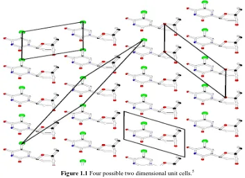
[image:15.595.128.481.370.627.2]The unit cell can be defined as the smallest repeating unit found within a crystal. It is possible that more than one repeating unit is present in the crystal (Figure 1.1).
3 Each unit cell is defined in terms of lattice points. Lattice points are the points in space about which the particles are free to move in a crystal. There are six parameters of the unit cell, three defining distances within the three dimensions (a, b and c) and one for each angle associated as shown in Figure 1.2.4
Figure 1.2 Parameters of a unit cell.5
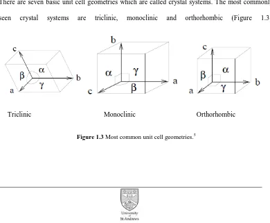
The Seven Crystal Systems
There are seven basic unit cell geometries which are called crystal systems. The most commonly seen crystal systems are triclinic, monoclinic and orthorhombic (Figure 1.3).
[image:16.595.115.505.425.746.2]Triclinic Monoclinic Orthorhombic
4 There are 230 space groups defined from the combination of 32 crystallographic point groups and the 14 Bravais lattices.6 The space group is a tool that describes the symmetry of the molecule within the unit cell. Two types of symmetry element exist in a crystal system known as point group symmetry and space group symmetry. Point group symmetry includes the inversion centres (-1) two fold axes (2), or mirror planes (m). Space group symmetry includes unit latticecentring (P, primitive; C, side-centred; I body centred or F; face centred) screw axes (21) and glide planes (a,b,c or n).6 Every crystal structure is explained by a combination of these symmetry operations. There is a specific notation for describing space groups: the first descriptor defines the lattice type (P, C, F, I), the next descriptors describe the point group symmetry of which the principal axis is noted first. For the remaining characters, different rules apply for different crystal systems.
Table 1.1 The seven crystal systems.
Crystal systems Lattice centring Axial lengths Axial angles Triclinic P a≠b≠c α, β, γ ≠ 90o Monoclinic PC a≠b≠c β≠90o and α, γ = 90o Orthorhombic PICF a≠b≠c α , β, γ = 90o
Hexagonal P a=b≠c α=β=90o and γ = 120o Trigonal PR a=b=c α=β=γ≠ 90o
Tetragonal PI a=b≠c α,β,γ=90o Cubic PIF a=b=c α,β,γ=90o
The Bragg Equation
5 scattering centres and thereby diffract X-rays. Diffraction can be constructive or destructive. As a result of this varying intensities can be observed in a diffraction pattern. X-ray diffraction can be understood by considering the Bragg equation.7
A section of a crystal with atoms arranged on a set of parallel planes (h k l) and spaceddistance d
apart is shown in Figure 1.4. When a beam of monochromatic X-ray with wave length λ strikes through the planes of the crystal at an angel θ, the rays reflected by the lower plane travel a longer distance than those reflected from the upper plane (Equation 1.1; n is an integer).
[image:18.595.120.538.317.530.2]nλ = 2d sinθ (1.1)
Figure 1.4Bragg’s law form reflections of incident radiation from successive lattice planes.
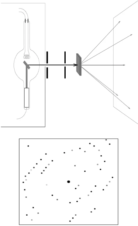
6
Figure 1.5 Schematic of single crystal X-ray diffraction; the diffracted X-rays produce a diffraction pattern.5
Obtaining a Crystal Structure
7 small loop onto a goniometer in the diffractometer. The crystal is then rotated whilst being irradiated with X-rays and multiple diffraction patterns are collected from each angle.
The diffraction pattern is then processed and spots of intensity are integrated and collected using e.g. CrystalClear software.2 This gives a set of hkl values and intensities which are used to deduce where peaks of electron density are situated.
The following steps are performed by a crystallographer: unit cell determination, data collection, data reduction, space group determination, structure solution and structure refinement.1
Growing a crystal
In order to form crystals, a nucleation should take place followed by crystal growth. But still growing good quality crystals is a difficult task. Different techniques can be applied to grow crystals. The most common methods used today are vapour diffusion, evaporation, solvent layering and cooling.
8 In the slow evaporation method, the sample is dissolved in a suitable solvent, generally one which can make a saturated solution, and then it is evaporated slowly over a period of time. Usually this is carried out at room temperature and the crystal may form when the solution has achieved supersaturation (Figure 1.6(a)).6
In the slow cooling crystallisation, prepare a saturated solution of the product at room temperature and place in a cold place, preferably in a freezer or in a dry-ice acetone bath. This is good for the moderately soluble substances.
9
Figure 1.6 Schematics of three popular methods of crystal growth. (a) Slow evaporation of the solvent, (b)
slow cooling of the solution and (c) gas-phase diffusion of a precipitant into a solution. (Adopted from
10
A flowchart for the steps involved in a crystal structure determination
1. Select a suitable crystal and mount it for X-ray study
2. Obtain unit cell geometry and preliminary symmetry information
3. Measure intensity data
4. Data reduction (various corrections applied)
5. Solve the structure a. Patterson methods b. Direct methods
7. Refine the structure model 6. Complete the structure – find all the atoms
11
Collecting data
The X-ray crystallographic data is obtained by introducing a single crystal to the X-ray diffractometer (Figure 1.7). Inside the diffractometer the X-rays are diffracted and the scattered beams are plotted against the refractive angle. A video camera is used to magnify the crystal in order to help the crystallographer to move the crystal to the correct position in the X-ray beam. A stream of e.g. cold gaseous N2 is passed over the crystal to lower the thermal vibrations of the
atoms and also to minimize the solvent diffusion out of the crystal during the data collection.2 This stream can be stopped to allow room temperature data collection to occur if this is of interest to the crystallographer, for example studying phase changes.
12 When a crystal is irradiated with a monochromatic beam it scatters the waves and results a specific diffraction pattern. These diffracted rays are then recorded, e.g. on a charge coupled device (CCD) area detector in the form of images. These images consist of different spots known as reflections. Valuable structural information can be revealed from the intensity and the position of each spot in a diffraction pattern. This includes the information on atomic positions, bond lengths and angles, torsion angles, etc.
Structure solution
There are two structure solution methods for solving the crystal structures using the electron density map, to overcome the phase problem; either Patterson methods or direct methods can be used.8 In the overall crystallographic process one of these methods is used. Once the process is successful, an electron density map is drawn.
Refining the structure
Refinement can include the addition or deletion of atoms, alteration of elements or accounting for thermal parameters. The aim is to optimize the fit of the model to the diffraction data. The fit is measured by the residual factor also called the R-factor. In general the lower the R-factor the better the model fits the collected data. Refinements are usually carried out until the lowest R-factor is obtained. The R factor is defined as follows:
(1.2) Where ;
14
References
1. P. Müller, Crystallogr. Rev., 2009, 15, 57.
2. A. L. Fuller, “Application of X-ray Crystallography: studies into the structural perturbations of peri-substituted naphthalene derivatives”, Ph.D. Thesis, University of St Andrews, 2009.
3. C. F. Campana, Analytical application note. BRUKER AXS Inc. : 2000.
4. D. E. Sands, in Introduction to Crystallography, W. A. Benjamin Inc., New York, 1969.
5. H. Kooijman, Interpretation of Crystal Structure Determination, version 2.3, undergraduate course notes, Utrecht University, 2005.
6. L. Ooi, Principles of X-ray Crystallography, Oxford University Press, Oxford, 2010.
7. A. R. West, Solid state Chemistry and its applications, John Wiley and Sons Ltd., New York, 1984.
Chapter 2
15
Introduction
Peri-substitution is a “double substitution of atoms or groups at the peri-positions” of naphthalene systems;1 positions 1- and 8- on the naphthalene ring or 5- and 6- on the acenaphthene backbone.1,2 In unsubstituted (“ideal”) naphthalene the peri-positions, occupied by two hydrogen atoms, are at a distance of ca. 2.5 Å.1-5 The naphthalene backbone is planar with unequal bond lengths, but internal angles are ca. 120°,1-5 with the exocyclic peri-bonds aligned parallel to each other.2,5 The presence of the CH2CH2 linker at the 1,2-positions in acenaphthene, however, results
in a slight deviation in the planarity of the carbon framework.5 Therefore, the internal angles in acenaphthene deviate from those in naphthalene, with angles ranging from 111-127°.5 The smallest angle is observed near to the CH2CH2 bridge (C1-C1a-C2, Figure 2.1), whilst the splay
angle has widened in the peri-region (C5-C5a-C6, Figure 2.1). Accordingly, the exocyclic bonds lean away from each other in different directions, thus increasing the peri-gap to a ca. 2.7 Å, compared to naphthalene.5
Figure 2.1 The geometry of peri-functionalities in naphthalenes, ortho-substitution in benzenes and peri
16 The peri-distances in acenaphthene and naphthalene are large enough to comfortably accommodate the two hydrogen atoms (ΣrvdW 2.18 Å),5,6 however, when larger atoms or groups
are located at the peri-positions they can experience greater steric compression.2-5 This steric strain can be released via four different possibilities; elongation of the peri-atom bonds (Figure 2.2,a), in-plane distortions (Figure 2.2,b ), out-of-in-plane deflections (Figure 2.2,c) and buckling of the acenaphthene backbone (Figure 2.2,d).2-5 Further relaxation of steric strain can be achieved through attractive interactions between peri-functionalities. X-ray crystallography is a widely used tool for the highly accurate determination of molecular structures. It can therefore be used to identify distortion of the acenaphthene backbone, as well as any changes in bond lengths and the
peri-distance, which are indications for the existence of weak intramolecular interactions. One particular interest of this thesis is to gain a thorough understanding of the structural features of
peri-substituted acenaphthenes.
Figure 2.2 The degree of steric strain and naphthalene deformation is determined by comparing a) peri
-distances, b) sum of the peri-region angles, c) in-plane and out-of-plane distortions and d) dihedral angles
17
Relieving steric pressure by elongating peri-atom bonds
Considering a large amount of energy is associated with only a small change in bond length,2,3,11 the elongation of bonds as a means of releasing the steric pressure in peri-substituted systems is uncommon (Figure 2.3). To get a better understanding of the C-X, C-Y bond lengthening in acenaphthene molecules, a Cambridge structural database system (CSD) search was narrowed down to acenaphthene structures containing a sulfur at one peri-substituent and the other position occupied with any atom other than hydrogen.
Figure 2.3 CSD search for peri-substituted acenaphthenes with the peri-positions containing one sulfur atom
and any atom other than hydrogen.
18
In-plane distortions
In-plane distortion of peri-functionalities can be deduced by looking at the angles around the bay region. In acenaphthene, the bay-region angles are C5-C6 (128°), C5-H (119°) and C5a-C6-H (113°) and sum to 360°. Therefore the degree of in-plane distortion occurring in substituted systems can be determined by comparing the splay angle (sum of the bay-region angles - 360°) to acenaphthene.4,6
In order to reduce the steric tension in these systems imposed by the close proximity of the substituents, the peri-bonds can bend outward to minimise the repulsive interactions (Figure 2.4 a). In-plane distortion can also be used to indicate the presence of a weak or strong bonding interaction between the peri-substituents if the exocyclic bonds bend inwards (Figure 2.4 b), compared to the parallel arrangement in acenaphthene (Figure 2.4 c).
Figure 2.4 In-plane deflections of the peri-functionalities at the 5 and 6 positions in acenaphthenes: repulsive
interactions (a), attractive interactions (b), and parallel alignment in acenaphthene (c).
19 bay-region deviate from ideal values. The largest splay angle (13.2°) was observed in an acenaphthene compound substituted with S-Ph and (SeMePh)+ moieties13 (Figure 2.5), showing the substituents lean outward to release steric tension. Conversely, the smallest splay angle was found in a disulfide acenaphthene derivative (-11.9°), illustrating that the substituents bend inward as a result of forming a strong covalent bond, thus reducing the sum of the bay angles (Figure 2.5).
Figure 2.5 In-plane distortion indicates the extent of both repulsive and attractive interactions between
substituents.13
Out-of-plane distortions
20 the acenaphthene backbone. Unsurprisingly it was found that the largest distortion occurred for the acenaphthene backbone containing bulky TePh-TePh as substituents (-0.404(1) Å Te1, 0.310(1) Å Te2; Figure 2.7).6 Much smaller deviations from the mean plane are observed when lighter congeners occupy the close 5,6-position, for example when SPh-SPh are substituents (-0.132(1) Å S1, 0.161(1) Å S2; Figure 2.7).6
Figure 2.6 Out-of-plane distortion: distance of the peri-substituents occupy relative to the acenaphthene
mean plane.
[image:34.595.256.368.248.372.2]A B
Figure 2.7 Line drawing of A Acenap(SPh)2and B Acenap(TePh)2 showing the difference in out-of-plane
21
Buckling in the acenaphthene ring
In addition to in- and out-of-plane distortions, the carbon framework may also undergo twisting to relieve the steric strain induced by the bulky peri-functionalities. Torsion angles associated with central bridging carbon atoms in acenaphthene (C5-C10) give a good indication of the amount of buckling taking place in the acenaphthene backbone; in acenaphthene the backbone is planar with angles ca. 0° or 180° (Figure 2.8).
A CSD search of torsion angles for S containing acenaphthene structures resulted 28 hits, with the disulfide structure displaying the least amount of distortion from planarity (179.84° and 179.55°). The largest torsion angles are observed for a Ag coordinated SPh acenaphthene derivative (AgS2
(SPh-SPh-AgS2acenap)2)14 with torsion angles of 172.24° and 172.42° indicating the backbone
has undergone a significant degree of distortion away from the ideal planar structure in order to relieve the steric tension .
Figure 2.8 Torsion angles in bold, run through the C5-C10 central bond and indicate the planarity of the
22
Three centre-four electron (3c-4e) type interactions
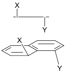
Recently the Woollins group has carried out extensive studies using acenaphthene molecules in which the peri-positions are occupied by larger heteroatoms, in order to gain a greater understanding of non-bonded interactions. This has been achieved by introducing chalcogen, phosphorus or halide substituents into the peri-positions.4-6 It has been suggested that the linear arrangement and the close proximity of the peri-positions (within the sum of the van dar Waals radii) which can occur in such systems, provides the correct geometry for promoting a three-centre four-electron (3c-4e) type interaction. When the three atoms are closely accommodated and linearly arranged, it is possible for a lone-pair orbital of one heteroatom to interact with an empty σ* anti-bonding orbital on the adjacent heteroatom. This attractive interaction has been shown to greatly influence the geometry of the peri-region (Figure 2.9).4-6
Figure 2.9 Anillustration of the linear arrangement and 3c-4e type interactions, where X is a halide and E is
23
Previous work on peri-substituted organotin compounds
In 1979, Mislow and co-workers15 reported the first example of an organotin substituted naphthalene compound, containing trimethyltin at both peri-positions (Figure 2.10). In their studies, they concluded that positioning the large tin moieties (∑rvdW Sn 4.34 Å) in close proximity
caused significant changes to the geometry of the compound. As might be expected, the compound displayed a significant degree of deformation away from that of naphthalene, with a notably large Sn∙∙∙Sn peri-distance of 3.864 Å, accompanied by exceptional in-plane and out-of-plane deviations of the peri-substituents, suggesting a large amount of steric strain is introduced between the bulky trimethyltin groups.
Figure 2.10 The structure of 1,8-bis(trimethylstannyl)naphthalene.15
Later in 2002, Gabbai et al., demonstrated that trimethyltin containing naphthalenes can be used for the preparation of heteronuclear peri-substituted compounds such as dimesitylboranes.16 These compounds readily undergo transmetallation reactions with Group 13 halides.
24 with the sodium salt of tributylstannane and Fry et al. synthesized 5,5,12,12-tetramethyldiacenaphtho[5,6-bc:5',6'-fg]-(1,5)distannocin in 1991 by reacting 5,6-dilithioacenaphthene with dimethyldichlorostannane (Figure 2.11).18 Nevertheless no crystal structure data for an organotin substituted acenaphthene was found in the Cambridge Structure database (CSD) at the start of this work.
Figure 2.11 Thestructures of 5-tributylstannylacenaphthene and
5,5,12,12-tetramethyldiacenaphtho[5,6-bc:5',6'-fg]-(1,5)distannocin.17,18
25 investigated, employing changes in bond lengths, bay-region angle splay, displacement of atoms from the mean plane and central acenaphthene torsion angles to help quantify the degree of acenaphthene distortion, which are all conveniently probed by the peri-distance. We are particularly interested in these compounds as there are only two reported examples of organotin acenaphthene compounds in the literature so far. As an extension to this, weak interactions, including H-bonding, π-π stacking and H-Cg bonding are also investigated.
26
References
1. P. Kilian, F. R. Knight and J. D. Woollins, Chem. Eur. J., 2011, 17, 2302.
2. A. L. Fuller, “Synthesis and Structural studies of group 16 peri-substituted naphthalenes and related compounds”, Ph.D. Thesis, University of St Andrews, 2010.
3. V. Balasubramaniyan, Chem. Rev., 1966, 66, 567.
4. M.-L. Lechner, K. S. Athukorala Arachchige, R. A. M. Randall, F. R. Knight, M. Bühl, A. M. Z. Slawin and J. D. Woollins, Organometallics, 2012, 31, 2922.
5. C. A. Coulson, R. Daudel and J. M. Robertson, Proc. R. Soc. London,Ser. A, 1951, 207, 306; D. W. Cruickshank, Acta Crystallogr., 1957,10, 504.
6. L. K. Aschenbach, . . night, . A. . andall, D. B. Cordes, A. Baggott, . B hl, A. . . Slawin and J. D. Woollins, Dalton Trans., 2012, 41, 3141.
7. A. C. Hazell, R. G. Hazell, L. Norskov-Lauritsen, C. E. Briant and D.W. Jones, Acta Crystallogr., Sect. C: Cryst. Struct. Commun., 1986, 42, 690.
8. G. E. Bacon, N. A. Curry and S. A. Wilson, Proc. R. Soc. London, Ser.A, 1964, 279, 98.
27 10. M. I. Kay, Y. Okaya and D. E. Cox, Acta Crystallogr., Sect. B: Struct. Crystallogr. Cryst.
Chem., 1971, 27, 26.
11. F. R. Knight, “Synthesis and structural studies of group 16 peri-substituted naphthalenes and
related compounds” Ph.D. Thesis, University of St Andrews, 2010.
12. R. L Avoyan, A.I Kitaigorodskii, and Yu.T Struchkov, Struct. Chem. (USSR), 1963, 4, 581.
13. C. G. M. Benson, Catherine M. Schofield, Rebecca A. M. Randall, Lucy Wakefield, Fergus R. Knight, Alexandra M. Z. Slawin and J. Derek Woollins, Eur. J. Inorg. Chem. 2013, 427.
14. F. R. Knight, Rebecca A. M. Randall, Lucy Wakefield, Alexandra M. Z. Slawin and J. Derek Woollins, Molecules 2012, 17, 13307.
15. J.F. Blount, F. Cozzi, J.R. Damewood, D.L. Iroff, U. Sjöstrand and K. Mislow, J. Am. Chem. Soc., 1980, 102, 99.
16. M. Schulte and F.P. Gabbao, Chem. Eur. J. 2002, 8, No. 16.
17. C.Weisemann, G.Schmidtberg and H.A Brune, J. Organomet. Chem. 1989, 365, 403.
18. R. H. Mitchell, M. Chaudhary, R. V.Williams, R. Fyles, Gibson, J. A. Smith and M, J. Fry,
Chapter 3
Synthetic and structural studies of sterically
26 The work undertaken in this chapter contributed to the manuscript ‘Sterically Crowded Tin Acenaphthenes’, published in the journal Organometallics in 2012.1 (Please see Collaboration Statement at the beginning of this thesis).
Introduction
The study of molecular bonding is of key importance in chemistry, biochemistry and materials science.1,2 Great advances have been made towards the understanding of covalent and ionic bonds, however, the large field of weak inter- and intramolecular interactions still holds mysteries. Organic frameworks with rigid backbones, such as acenaphthene, are highly suitable for the study of interatomic interactions. The short “natural” peri-distance (2.44 Å) and the rigidity of the aromatic system causes considerable strain between the peri-substituents.3 Only the hydrogen substituted acenaphthene is ‘relaxed’.2-5 As a consequence, substitutions in the peri-position lead
to in- and out-of-plane distortions, which often result in buckling of the ring system. In order to relax this geometric strain, weak bonding interactions can exist between the peri-substituents.5 We speculated that due to the large van der Waals radius of tin (2.17 Å) organo-tin acenaphthenes could be expected to be good candidates to demonstrate weak interactions.
Up to this point there has been limited research on organo-tin acenaphthene compounds, however, the X-ray structure of a naphthalene bearing iodine and SnPh3 at the peri-positions has recently
27 systems containing group 15/16 peri-atomshave been thoroughly investigated with intramolecular donor-acceptor interactions across the peri-gap leading to 3c-4e type bonding (Figure 3.1).
Figure 3.1 Examples of peri-substituted molecules stabilized by weak intramolecular interactions.8-10
Here we report the synthesis and structural studies of peri-substituted 5-bromo-6(organostannyl) acenaphthene compounds, in which elements from group 17(Br) and 14(Sn) occupy the close 5,6-positions on the acenaphthene backbone, but which are formally non-bonded. For their synthesis, 5,6-dibromoacenaphthene was treated with a selection of different organo-tin reagents (Ph3SnCl,
Ph2SnCl2, Bn2SnCl2, Bu2SnCl2, SnCl4), affording the series of mixed bromo-tin derivatives 1
(Acenap[SnPh3][Br], 2 (Acenap[SnPh2Cl][Br] and 3-6 bis (Acenap[SnX2][Br2] (X= Cl, Bu, Ph,
28
29
Section 1
Synthesis and structural studies of mono-substituted 6-bromoacenaphth-5-yl-triphenyltin (1)
and
6-bromoacenaphth-5-yl-diphenyltin chloride (2)
6-bromoacenaphth-5-yl-triphenyltin(1) and 6-bromoacenaphth-5-yl-diphenyltin chloride(2) were synthesized by reacting 5,6-dibromoacenaphthene with a one equivalent of n-butyllithium at −40 °C in diethyl ether, followed by subsequent addition of SnPh3Cl and SnPh2Cl2, respectively,
[yield: 32% (1), 23% (2); Scheme 3.1 and 3.2].
Scheme 3.1 The preparation of 6-bromoacenaphth-5-yl-triphenyltin 1 from 5,6-dibromoacenaphthene.
30
Scheme 3.2 The preparation of 6-bromoacenaphth-5-yl-diphenyltin chloride 2 5,6-dibromoacenaphthene.
Conditions: i) nBuLi (1 equiv), Et2O, -40 ºC, 1 h; ii) SnPh2Cl2 (1 equiv), Et2O, 1 h.
Compounds 1 and 2 were characterised by elemental analysis, 1H, 13C and 119Sn NMR spectroscopy. The 119Sn NMR spectra of 1 and 2 display the expected singlets at -82 ppm and -70 ppm, respectively. To date there are no tin-substituted acenaphthene structures known in the literature for comparison with the compounds studied here. While the 119Sn NMR shifts of 1 and 2
are actually higher than for the phenyl analogue (Ph4Sn), a large upfield shift can be seen for 2, in
comparison to Ph3SnCl (Table 3.1), consistent with a higher coordination number at the tin atom
as a result of the interaction between the peri-substituents.
Table 3.1119Sn NMR spectroscopy data for compounds 1-2 and analogous compounds where the
acenaphthene is replaced by a phenyl group; all spectra run in CDCl3, δ (ppm).
Compound δ (ppm) Compound δ (ppm)
1 -82 Ph4Sn -137
31
X ray investigations
Crystals for 1 suitable for X-ray crystallography were obtained by diffusion of hexane into a saturated solution of the product in tetrahydrofuran (THF); the data refined in the Pbca space group (R1 = 3.59% (1)). Suitable single crystals for 2 were obtained by slow evaporation of hexane into a saturated solution of the compound in dichloromethane; crystallising in the P21/n
space group (R1 = 7.53% (2)). Both compounds crystallise with only one molecule in the asymmetric unit (Figures 3.3, 3.4). Selected interatomic distances, angles and torsion angles are listed in Table 3.2, further crystallography data for 1 and 2 can be found in Appendix 3.
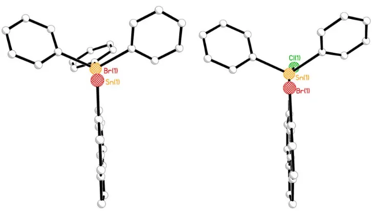
Figure 3.3 The crystal structure of 6-bromoacenaphth-5-yl-triphenyltin 1(hydrogen atoms omitted for
[image:49.595.119.498.119.393.2]
32
Figure 3.4 The crystal structure of 6-bromoacenaphth-5-yl-diphenyltin chloride 2(hydrogen atoms omitted
for clarity).
The steric repulsion imposed in 1 and 2, by the crowded tin moieties located in the bay region is relieved by in-plane and out-of-plane deviation supplemented by significant buckling of the acenaphthene skeleton (see the central C-C-C-C torsion angles of the acenaphthene framework Table 3.1). The magnitude of geometrical deformation of acenaphthene is related to the bulkiness of the tin functionalities which occupy the peri-positions in the acenaphthene molecules. This can be identified when comparing the peri-distances for the two compounds. In 1, substituents reside in close proximity, with a non-bonded distance of 3.340(3) Å whereas 2 displays a much shorter
peri-distance of 3.143(2) Å, due to less bulkier substituents residing at the peri-positions and additionally the presence of the highly electronegative chlorine atom (SnPh2Cl), which enhances
[image:49.595.219.392.128.386.2]33 sum of the van der Waals radii for tin and bromine for both compounds (sum of vdW of Sn and Br, 4.02 Å), with distances 83% (1) and 78% (2) of the vdW sum (Table 3.1). These short weak interatomic peri-distances indicate the possible existence of non-covalent interactions.3
The bromine and tin atoms show greater deviations from the acenaphthene ring plane in 1 with the Sn lying -0.121(1) Å below the plane and Br displaced 0.1494 Å above, which is explained by the presence of the bulky triphenyl tin moiety sitting at one of the peri-positions. Minor out-of-plane distortion, however, is observed in 2 with the Sn and Br atoms sitting 0.076(1) Å and -0.094(1) Å from the mean plane respectively (Figure 3.2). Further distortion is provided by in-plane deviations of the exocyclic peri-bonds, with angles around the bay region affording a splay angle for 2 of 15.6° (sum of the peri-region angles - 360°), noticeably smaller than that observed in 1
34
Table 3.2 Selected bond lengths (Å) and angles (°) for 1 to 2.
1 2
Peri-region-distances
Br(1)···Sn(1) 3.340(3) 3.145(2) ΣrvdW - Br(1)···Sn[a] 0.680 0.875
%rvdW[a] 83 78
Br(1)-C(9) 1.907(4) 1.918(11) Sn(1)-C(1) 2.157(5) 2.147(11)
Acenaphthene bond lengths
C(1)-C(2) 1.395(6) 1.425(15) C(2)-C(3) 1.413(6) 1.411(17) C(3)-C(4) 1.361(6) 1.372(16) C(4)-C(5) 1.415(6) 1.428(15) C(5)-C(10) 1.423(6) 1.417(15) C(5)-C(6) 1.413(6) 1.422(15) C(6)-C(7) 1.361(6) 1.334(16) C(7)-C(8) 1.421(6) 1.458(18) C(8)-C(9) 1.359(6) 1.375(16) C(9)-C(10) 1.429(6) 1.418(15) C(10)-C(1) 1.437(6) 1.417(15) C(4)-C(11) 1.509(6) 1.522(16) C(11)-C(12) 1.560(7) 1.529(17) C(12)-C(6) 1.507(6) 1.522(17)
Peri-region bond angles
Br(1)-C(9)-C(10) 120.2(3) 119.7(8) C(1)-C(10)-C(9) 130.9(4) 130.5(10) Sn(1)-C(1)-C(10) 129.0(3) 125.4(8) Σ of bay angles 380.1(6) 375.6(15)
35
In and out-of-plane displacement
Br(1) 0.149(1) -0.094(1) Sn(1) -0.121(1) +0.076(1) C:(6)-(5)-(10)-(1) -179.3(4) 178.9(9) C:(4)-(5)-(10)-(9) -176.5(4) 176.9(9)
[a]
van der Waals radii used for calculations: rvdW (Sn) 2.17 Å, rvdW (Br) 1.85 Å [b] Splay angle: Σ of the
[image:52.595.132.495.282.488.2]three bay region angles – 360.
Figure 3.5 The structures 1 and 2 showing the planarity of the acenaphthene backbone.
The Sn-C1 distances (2.1 Å) are within the standard range for typical Sn-C bonds found in CSD search (2.1 ± 0.5 Å) for both 1 and 2. This shows that despite the steric effects caused by the large
36 degree of distortion enforced by the rigid acenaphthene backbone (Table 3.2). It is interesting to note that the sum of the C(1)-Sn(1)-C(19), C(1)-Sn(1)-C(25), and C(19)-Sn(1)-C(25) angles in 1
is 345°; wider than the tetrahedral (328.5°) but not large enough (360°) for a perfect trigonal bipyramid. The main reason for these distortions appears to be the presence of weak Sn···Br interactions in these systems coupled with the rigidity of the acenaphthene backbone.
Table 3.3 Bond angles [°] categorising the geometry around Sn in 1 and 2.
Angles around the Sn atom 1 2
C(1)-Sn(1)-C(13) 107.73(15) - C(1)-Sn(1)-C(19) 114.37(15) - C(1)-Sn(1)-C(25) 111.15(15) - C(13)-Sn(1)-C(19) 99.82(15) - C(13)-Sn(1)-C(25) 102.26(15) - C(19)-Sn(1)-C(25) 119.34(15) - Cl(1)-Sn(1)-C(1) - 100.7(3) Cl(1)-Sn(1)-C(13) - 96.1(3) Cl(1)-Sn(1)-C(19) - 100.3(3) C(1)-Sn(1)-C(13) - 121.1(4) C(1)-Sn(1)-C(19) - 114.2(4) C(13)-Sn(1)-C(19) - 117.5(4)
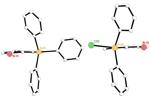
The Sn-CPh and Sn-Cl moieties in 1 and 2 lie in a similar location producing quasi-linear
three-body fragments; Br∙∙∙Sn-CPh in 1 (179.88o) and Br∙∙∙Sn-Cl in 2 (172.06°) (Figure 3.6). The
[image:54.595.155.472.276.491.2]
37 structures. The WBI for 2 is 0.11 which indicates the presence of a weakly attractive interaction between the Sn···Br peri substituents, and as expected much more significant than in 1 (0.07). This is due to the presence of the highly electronegative chlorine atom on the Sn atom in 2, which enhances the weak Sn···Br interaction, formed by electron donation from the bromine atom into low-lying empty orbitals on tin.
Figure 3.6 The molecular configurations of 1 and 2 showing the orientation of the substituents bound to
acenaphthene.
38 structure, however centroid (Cg) hydrogen bonds (H-Cg) are present (Table 3.4, Figure 3.7 and 3.8). In 1 and 2, the H atom attached to C11 interacts with the centroid of a separate molecule and due to the orientation of the second molecule the C11-H11A atom can similarly interact with a centroid from the first molecule, resulting in a back interaction (Figure 3.7 and 3.8). In 1 and 2, the hydrogen atoms from both the acenaphthene and the attached phenyl rings interact with centroids of further phenyl rings from different molecules. In contrast to the structure of 1, compound 2
exhibits a weak donor–accepter type interaction due to the close proximity of the large Cl atom and H2, with the H2-Cl1 distance 2.72 Å (Figure 3.8).
Table 3.4 H – Cg interactions for 1 and 2;Cg2:6 membered C5-C6-C7-C8-C9-C10; Cg3:6 membered
C1-C2-C3-C4-C5-C10; Cg4: 6 membered C5-C6-C7-C8-C9-C10; Cg6: 6 membered
C19-C20-C21-C22-C23-C24; generated in Platon.
Compound X H Cg H...Cg Distance /Å X...Cg Distance /Å Angle /° 1 C11 H11A 2 2.72 3.4942 136
C15 H15 3 2.82 3.6398 145
2 C11
H11B
[image:56.595.135.499.122.399.2]
39
[image:57.595.118.505.122.349.2]
40
41
Section 2
Synthesis and structural studies of bis(6-bromoacenaphth-5-yl)tin dichloride
and
bis(6-bromoacenaphth-5-yl)dibutyltin
Single substitution reactions of 5,6-dibromoacenapthene, via lithium halogen exchange followed by treatment of a suitable tin dichloride, yielded compounds of the type bis ({AcenapBr}2SnX2
(X= Cl (3), Bu (4)) (Scheme 3.3). For their synthesis, 5,6-dibromoacenapthenewas independently reacted with n-butyllithium (1 equivalent) at −40 °C in diethyl ether and subsequent addition of a ½ equivalent of SnCl2 and SnBu2Cl2, respectively, 3 and 4 [35% (3), 14% (4); Scheme 3.1 and
3.2].
Scheme 3.3 The preparation of bis(6-bromoacenaphth-5-yl)tin dichloride 3 and
bis(6-bromoacenaphth-5-yl)dibutyltin 4 from 5,6-dibromoacenaphthene. Conditions: i) nBuLi (1 equiv), Et2O, -40 ºC, 1 h; ii) SnCl2
42 Both compounds were fully characterised by elemental analysis, 1H, 13C and 119Sn NMR spectroscopy. The 119Sn NMR spectra of 3 and 4 display single peaks at -132.2 ppm and -31.4 ppm, respectively, with the presence of the two highly electronegative chlorine atoms producing a substantial upfield shift compared to the two butyl groups.
X ray investigations
[image:60.595.177.445.378.619.2]
43
Figure 3.9 The crystal structure of bis(6-bromoacenaphth-5-yl)dichlorotin3 (hydrogen atoms omitted for
clarity).
Figure 3.10 The crystal structure of bis(6-bromoacenaphth-5-yl)dibutyltin4 (hydrogen atoms omitted for
44 The molecular structures of bis-tin derivatives 3 and 4 are constructed from two crystallographically different acenaphthene fragments which couple through a central pseudo -tetracoordinated tin atom in a geminal fashion (Figure 3.9 and 3.10). In 3 and 4,the acenaphthene fragments lie with angles of 37° and 61° respectively between the two mean planes, keeping the Br atoms at a close distance to the tin center. The steric strain forced upon the peri-substituents by the rigid acenaphthene scaffolds is released by the formation of weakly attractive intermolecular 3c-4e type interactions which are presumably between the lone pair of electrons on Br and the electropositive Sn atom. This results in short Sn∙∙∙Br distances within the sum of van der Waals radii (Sn1-Br1 3.174 (1) Å 3, Sn1-Br 3.398(1) Å 4). This is supported by the alignment of the
Sn-CBu ,Sn-Cacenap and Sn-Cl moieties in 3 and 4,which sit in a linear arrangement, leading to the
construction of comparable three-body fragments; Br∙∙∙Sn-Cl in 3 (179.23°) and Br∙∙∙Sn-CBu in 4
(175.72°) (Figure 3.12).
In both compounds the geometry around the Sn atom deviates significantly from an ideal tetrahedral geometry, with angles in the range 98.74°-142.1° (Table 3.4). In dichloride 3, the tin geometry is somewhat complicated, which can be described as either 2-coordinate (linear), 4-coordinate (square planar) or 6-4-coordinate (octahedral) depending upon the interpretation of the Sn-Y bonding interactions (Figure 3.12). If the two Sn-Br interactions are classified as non-bonding and the Sn-Cl bond thought of as having ionic character due to the electronegativity difference between the Sn and Cl atoms, the tin center would be coordinated to just the two acenaphthene fragments, with a Cacenap-Sn-Cacenap bond angle of 179.23(4)° displaying linear
45 attractive donor-acceptor interactions between Br and Sn complete a distorted octahedral geometry around the tin center.
Table 3.4 Bond angles [°] categorising the geometry around Sn in 3 and 4.
Angles around the Sn atom 3 4
C(1)-Sn(1)-C(13) 142.1(4) 142.1(4) - - C(1)-Sn(1)-Cl(1) 103.6(3) 103.6(3) - - C(1)-Sn(1)-Cl(2) 98.9(2) 98.9(2) - - Cl(1)-Sn(1)-Cl(2) 98.74(10) 98.74(10) - - C(13)-Sn(1)-Cl(1) 102.4(3) 102.4(3) - - C(13)-Sn(1)-Cl(2) 103.7(3) 103.7(3) - - C(1)-Sn(1)-C(13) - - 104.7(3) 104.7(3) C(1)-Sn(1)-C(25) - - 125.8(3) 125.8(3) C(1)-Sn(1)-C(29) - - 102.6(4) 102.6(4) C(13)-Sn(1)-C(25) - - 107.5(3) 107.5(3) C(13)-Sn(1)-C(29) - - 104.9(4) 104.9(4) C(25)-Sn(1)-C(29) - - 109.6(4) 109.6(4)
The degree of steric hindrance operating between the peri-substituents of 3 and 4 issubstantially larger than compared to the mono-compounds of Section 1. The out-of-plane displacement of the
[image:63.595.167.464.119.346.2]
46
Figure 3.12 The structures of 3 and 4 showing the planarity of the acenaphthene backbone.
Table 3.5 Selected bond lengths (Å) and angles (°) for 3 to 4.
3 4
Fragment 3a 3b 4a 4b
Peri-region-distances
Br(1)···Sn(1) 3.174(2) 3.174(2) 3.398(1) 3.370(1)
47 %rvdW
[a]
79 79 85 84
Br(1)-C(9) 1.910(8) 1.919(9) 1.911(9) 1.904(7) Sn(1)-C(1) 2.125(8) 2.142(9) 2.163(8) 2.211(8)
Acenaphthene bond lengths
C(1)-C(2) 1.393(13) 1.383(12) 1.405(13) 1.374(11) C(2)-C(3) 1.423(12) 1.438(13) 1.416(13) 1.430(10) C(3)-C(4) 1.363(13) 1.368(11) 1.353(11) 1.364(13) C(4)-C(5) 1.423(13) 1.410(11) 1.407(12) 1.424(12) C(5)-C(10) 1.411(11) 1.410(12) 1.423(12) 1.419(10) C(5)-C(6) 1.413(11) 1.406(11) 1.399(10) 1.417(13) C(6)-C(7) 1.354(13) 1.382(12) 1.375(12) 1.377(13) C(7)-C(8) 1.420(12) 1.399(12) 1.429(13) 1.422(11) C(8)-C(9) 1.381(11) 1.374(10) 1.360(11) 1.368(13) C(9)-C(10) 1.435(13) 1.443(11) 1.436(12) 1.419(12) C(10)-C(1) 1.436(11) 1.439(10) 1.450(10) 1.447(13) C(4)-C(11) 1.542(12) 1.523(12) 1.507(12) 1.511(11) C(11)-C(12) 1.549(14) 1.573(11) 1.556(11) 1.552(13) C(12)-C(6) 1.518(12) 1.530(13) 1.499(13) 1.506(10)
Peri-region bond angles
Br(1)-C(9)-C(10) 119.8(6) 119.6(6) 120.5(6) 121.4(6) C(1)-C(10)-C(9) 129.4(7) 130.1(8) 129.8(8) 131.1(7) Sn(1)-C(1)-C(10) 125.4(6) 125.3(6) 130.0(7) 128.0(6) Σ of bay angles 374.6(11) 375.0(12) 380.3(12) 380.5(11)
Splay angle[b] 14.6 15.0 20.3 20.5 C(4)-C(5)-C(6) 112.3(7) 112.0(8) 111.8(8) 110.8(7)
In and out-of-plane displacement
Br(1) +0.177(1) +0.072(1) -0.002(1) -0.002(1) Sn(1) -0.390(1) -0.176(1) -0.400(1) -0.011(1) C:(6)-(5)-(10)-(1) -175.9(6) -179.7(7) 179.9(8) 179.0(7)
C:(4)-(5)-(10)-(9) 179.9(6) 179.7(7) -179.0(7) 178.7(7)
[a]
van der Waals radii used for calculations: rvdW (Sn) 2.17 Å, rvdW (Br) 1.85 Å [b] Splay angle: Σ of the
three bay region angles – 360.
48 to accommodate the repulsion caused by the peri substituents, but nevertheless is concurrent with standard Sn-C distances from a CSD search for typical Sn-C bond lengths (2.10 Å).1
In 4, in addition to the H-Cg interactions, there is a weak H-bond between the hydrogen of the acenaphthene and the bromine atom. This suggest that the addition of the butyl group instead of the phenyl group, allows the substituents to get close enough to make a weak H···Br bond (Figure 3.14). Whilst there is no π-π stacking seenin 3 and 4 (as the closest centroids are 3.82 Å and 3.89 Å in distance), there are H-Cg interactions seen in each structure (Table 3.6). In both these structures the molecules pack in pairs with one molecule rotated through 180°, lying on top of the other, allowing for the acenaphthene of one molecule to interact through the C11 and C12 hydrogens (Figure3.13 and 3.14). In addition, there are two weak donor-accepter interactions present in 3, due to the alignment of the bromine atoms in the peri-region (C30-H30B∙∙∙Br1 - 2.80 Å, C41-H41∙∙∙Br3 – 2.92 Å), and similarly, 4 displays two donor-acceptor interactions with H-Cl (C2-H2∙∙∙Cl1, 2.76 Å and C14-H14∙∙∙Cl2, 2.76 Å).
Table 3.6 H – Cg interactions for 3 and 4,Cg1:6 membered C1-C2-C3-C4-C5-C10; Cg2:6 membered
C5-C6-C7-C8-C9-C10; Cg3:6 membered C13-C14-C15-C16-C17-C22; Cg4: 6 membered
C17-C18-C19-C20-C21-C22, generated in Platon.
Compound X H Cg H...Cg Distance /Å X...Cg Distance /Å Angle /°
C11 H11B 2 2.80 3.6495 144
1 C12 H12A 1 2.77 3.5813 140 C25 H25B 3 2.81 3.5887 136 C11 H11B 2 2.95 3.7815 143 C12 H12A 3 2.92 3.6352 129
49
Figure 3.13 H- Centroid and donor-acceptor interactions within the structure of 3.12,13
[image:66.595.139.486.134.383.2]50
Section 3
Synthesis and structural studies of bis(6-bromoacenaphth-5-yl)diphenyltin
and
bis(6-bromoacenaphth-5-yl)dibenzyltin
To complete the series, analogues of compounds 3 and 4 containing the bulkier diphenyltin (5) and dibenzyltin (6) moieties at the peri-positions were prepared following the same procedure. 5,6-dibromoacenapthene was treatedwith a single equivalent of n-butyllithium at −40 °C in diethyl ether followed by addition of ½ equivalent of SnPh2 and SnBz2Cl2, respectively [10% (5), 60% (6);
Scheme 3.4]
Scheme 3.4 The preparation of bis(6-bromoacenaphth-5-yl)diphenyltin 5 and
bis(6-bromoacenaphth-5-yl)dibenzyltin 6 from 5,6-dibromoacenaphthene. Conditions: i) nBuLi (1 equiv), Et2O, -40 ºC, 1 h; ii) SnPh2
51 Both compounds were characterised by elemental analysis, 1H and 13C NMR spectroscopy. 5 was additionally characterised by 119Sn NMR spectroscopy, however due to poor solubility this was not possible for 6. As expected, the 119Sn NMR spectrum of 5 exhibited a single peak at -116 ppm, lying between the values observed for 3 and 4.
X ray investigations
Colourless crystals, suitable for characterisation by single crystal X-ray crystallography were obtained for 5 and 6 from hexane diffusion into saturated solutions of dichloromethane. Diphenyltin derivative 5 (Figure 3.15) crystallises in the monoclinic system with space group P-1 (R1 = 5.12%), whilst benzyltin 6 (Figure 3.16) crystallises in the monoclinic system with space group of P21/C (R1 = 5.04%). Both compounds crystallise with one molecule in the asymmetric
52
Figure 3.15 The crystal structure of bis(6-bromoacenaphth-5-yl)diphenyltin5 (hydrogen atoms omitted for
clarity).
Figure 3.15 The crystal structure of bis(6-bromoacenaphth-5-yl)dibezyltin6 (hydrogen atoms omitted for
[image:69.595.220.402.130.362.2] [image:69.595.195.439.421.640.2]53 The increased size of the substituents bound to Sn in 5 and 6 is accommodated by greater in- and out-of-plane distortion of the exocyclic peri-bonds. This is illustrated by looking at the angles between the peri-substituents, with the sum of the bay region angles increasing to 380.4(10)° in 5
and 378.8(9)° in 6, much larger than the distortion exhibited by 2 (375.6(15) Å). A significant increase is also observed in the degree of out-of-plane displacement compared to 2, with Br experiencing the greatest displacement from the plane (~0.2Å). In both molecules, Br sits above the plane whilst Sn lies above and below the mean acenaphthene plane, respectively [Sn (1)
0.054(1) Å 5, -0.306(4) Å 6; Br (1) 0.311(5) Å 5, 0.126(4) Å 6]. The mean plane deviations can be seen in Figure 3.17. Further distortion from planarity can be seen via buckling of the C-C-C-C torsion angles. Whilst the C(6)-C(5)-C(10)-C(1) torsion anglealmost approaches 180° (179.2(7)°), the C(4)-C(5)-C(10)-C(9) angle in contrast is 176.8(8)° demonstrating the degree of buckling occurring in the carbon backbone in order to relieve the steric strain caused by the bulkier Sn moiety. In addition, the C11-C12 bond (1.570(10) Å) has elongated to relieve the twisting of the acenaphthene ring, and it is larger than that of 5,6-dibromoacenaphthene (1.549(9)Å). The other difference is the C5-C10 distance which increases from 1.42 Å to 1.44 Å.
The Sn∙∙∙Br distance in 5 (3.339(3) Å) is notably longer than that of 2 (3.1451(15) Å), but it is statistically indistinguishable from the distance in 1 (3.340(6) Å). However, the peri-distance in 6
[image:71.595.115.482.123.349.2]
54
Figure 3.16 The structures of compounds 5 and 6 showing the planarity of the acenaphthene backbone.
Table 3.7 Selected bond lengths (Å) and angles (°) for 5 to 6.
5 6
Fragment 5a 5b 6a 6b
Peri-region-distances
Br(1)···Sn(1) 3.328(1) 3.338(1) 3.299(1) 3.393(1)
ΣrvdW - Br(1)···Sn[a] 0.692 0.682 0.721 0.627
[image:71.595.107.517.443.750.2]55 Br(1)-C(9) 1.913(8) 1.899(9) 1.902(6) 1.908(8) Sn(1)-C(1) 2.161(7) 2.129(9) 2.168(6) 2.171(7)
Acenaphthene bond lengths
C(1)-C(2) 1.430(10) 1.411(10) 1.386(8) 1.423(10) C(2)-C(3) 1.413(11) 1.407(13) 1.432(9) 1.371(12) C(3)-C(4) 1.374(10) 1.356(12) 1.352(9) 1.361(12) C(4)-C(5) 1.394(10) 1.411(11) 1.420(8) 1.432(10) C(5)-C(10) 1.446(10) 1.391(12) 1.415(9) 1.441(10) C(5)-C(6) 1.417(9) 1.404(12) 1.416(9) 1.380(10) C(6)-C(7) 1.359(11) 1.358(11) 1.370(9) 1.388(13) C(7)-C(8) 1.407(12) 1.414(13) 1.417(9) 1.384(13) C(8)-C(9) 1.368(10) 1.366(12) 1.372(10) 1.368(11) C(9)-C(10) 1.416(11) 1.446(10) 1.424(8) 1.421(10) C(10)-C(1) 1.413(9) 1.451(11) 1.422(9) 1.420(9) C(4)-C(11) 1.513(11) 1.511(13) 1.516(9) 1.516(11) C(11)-C(12) 1.570(10) 1.545(12) 1.567(10) 1.517(12) C(12)-C(6) 1.512(11) 1.513(13) 1.505(9) 1.477(12)
Peri-region bond angles
Br(1)-C(9)-C(10) 119.7(5) 120.2(6) 120.1(5) 120.0(5) C(1)-C(10)-C(9) 130.0(7) 127.1(8) 130.1(6) 130.8(6) Sn(1)-C(1)-C(10) 130.7(6) 131.6(6) 128.4(4) 131.3(5) Σ of bay angles 380.4(10) 378.9(12) 378.6(9) 382.1(9)
Splay angle[b] 20.4 18.8 18.6 22.1 C(4)-C(5)-C(6) 111.9(7) 112.4(8) 110.9(6) 111.0(7)
In and out-of-plane displacement
Br(1) +0.311(1) +0.266 +0.126 -0.043 Sn(1) +0.054(1) -0.374(1) -0.306 -0.053 C:(6)-(5)-(10)-(1) 179.2(7) -175.2(6) 179.5(5) 177.4(6) C:(4)-(5)-(10)-(9) -176.8(8) 179.9(6) -175.7(5) 179.4(6)
[a]
van der Waals radii used for calculations: rvdW (Sn) 2.17 Å, rvdW (Br) 1.85 Å [b] Splay angle: Σ of the
three bay region angles – 360.
56 the two acenaphthenyl groups C(1)-Sn(1)-C(13) (123.8 (3)° 5, 126.7(3)° 6) is significantly larger than the typical 109.5°. As a result of this the other angles are reduced in size (~4-6°) compared to
1 and 2.
Table 3.8 Bond angles [°] categorising the geometry around Sn in 5 and 6.
Angles around the Sn atom 5a 5b 6a 6b
C(1)-Sn(1)-C(13) 123.8(3) 123.8(3) 126.7(3) 126.7(3) C(1)-Sn(1)-C(25) 107.8(3) 107.8(3) 106.2(3) 106.2(3) C(1)-Sn(1)-C(31) 104.2(3) 104.2(3) - - C(13)-Sn(1)-C(25) 109.2(3) 109.2(3) 106.7(3) 106.7(3) C(13)-Sn(1)-C(31) 108.5(3) 108.5(3) - - C(25)-Sn(1)-C(31) 101.1(3) 101.1(3) - - C(1)-Sn(1)-C(32) - - 106.4(3) 106.4(3) C(13)-Sn(1)-C(32) - - 104.2(3) 104.2(3) C(25)-Sn(1)-C(32) - - 104.9(3) 104.9(3)
The favourable quasi-linear arrangement can be seen in both structures, with Br(1)∙∙∙Sn(1)-C-(benzyl) and Br∙∙∙Sn(1)-C(phenyl) aligning along the plane and angles approaching 180° (176.0(2)° 5, 172.1(2)° 6), suggesting the possibility of 3c-4e type interactions.
57 is known to occur. In 5 and 6,hydrogen atoms from both the acenaphthene and the attached phenyl rings interact with phenyl rings from neighbouring molecules in a slipped conformation.
Table 3.9 H – Cg interactions for 5 and 6,Cg1:6 membered C1-C2-C3-C4-C5-C10; Cg2:6 membered
C5-C6-C7-C8-C9-C10; Cg3:6 membered C13-C14-C15-C16-C17-C22; Cg4: 6 membered
C17-C18-C19-C20-C21-C22, generated in Platon.
Compound X H Cg H...Cg Distance /Å X...Cg Distance /Å Angle /°
C8 H5 5 2.63 3.5250 161
5 C15 H15 6 2.60 3.3959 144 C20 H15 6 2.88 3.7476 156 C27 H27 4 2.81 3.5554 138 C34 H34 4 2.71 3.5434 149 C24 H24B 4 2.78 3.6473 146
58
[image:75.595.202.435.132.423.2]59
Figure 3.18 H- Centroid and donor-acceptor interactions within the structure of 6.12,13
DFT calculations were performed for compounds 1-6 at the B3LYP/SBKJC level, chosen for its good performance during initial tests on 1,8-bis(trimethylstannyl)naphthalene.1 In this case, the structure in the crystal was used as a starting geometry. The calculated structures and crystal structures are in good agreement.
[image:76.595.131.478.116.381.2]60 stable trans form, the Br···Sn distance decreases from 3.44 to 3.31 Å, with a corresponding increase in the WBI from 0.07 to 0.11. Therefore, a chlorine in a trans position strengthens the Br···Sn interaction.1
Conclusion
Steric strain caused by larger atoms occupying the peri-positions of acenaphthene, is relieved by buckling of the acenaphthene backbone and in- and out-of-plane displacements. All the compounds studied here show a significant deviation from the ideal acenaphthene structure. Compounds 1, 4 and 5 show the greatest distortion of the acenaphthene ring, corresponding to the much bulkier peri-substituents.
Figure 3.19 shows all the peri-distances of the compounds studied in this chapter, with a noticeable increase in the peri-distance with bulkiness of the groups bound to the Sn atom. Compound 2 has the smallest peri-distance, and is much smaller than 1. This shows that by replacing SnPh3 in 1 with SnPh2Cl in 2 the bulkiness of the tin decreases, subsequently reducing
the amount of steric strain, there is less repulsion, a stronger donor-acceptor interaction and thus overall a smaller peri-distance. A similar trend is observed in the bis-derivatives with dichloride 3
61
Figure 3.19 peri-distances for the compounds 1-6.
The quasi-linear Br-Sn-Y three-body fragments present in the studied compounds, in which the Sn∙∙∙Br peri-distances are within the sum of van der Waals radii (4.10 Å) and angles approach 180°, suggests the presence of weakly attractive 3c-4e type interactions. This is supported by DFT calculations with Wiberg bond indices of 0.07-0.1 calculated. According to NBA analysis, the charge on Sn atom is +2 in all compounds studied. Non-covalent interactions may thus be another significant source for the Br···Sn interactions, in addition to the contributions from the donor−acceptor interactions.1
3.34 3.145 3.174 3.398 3.328 3.299 1 2 3 4 5 6
Peri-distances for Acenap[SnPh3][Br], Acenap[SnPh2Cl][Br], bis(acenap[SnX2][Br]
(X= Cl, Bu,Ph,Bz))
Peri-distances (Å)
SnPh3 SnPh2Cl
bis-acenap(SnCl2)
bis-acenap(SnBz2)
[image:78.595.122.503.118.426.2]62
Experimental
All experiments were carried out under an oxygen- and moisture-free nitrogen atmosphere using standard Schlenk techniques and glassware. Reagents were obtained from commercial sources and used as received. Dry solvents were collected from a MBraun solvent system. 5,6-Dibromoacenaphthene was prepared following standard literature procedures starting from acenaphthene.2-4 Elemental analyses were performed by the London Metropolitan University School of Human Sciences Microanalysis Service. 1H and 13C NMR spectra of 2, 3, and 8 were recorded on a Bruker Avance 300 MHz spectrometer. 1H and 13C NMR spectra of 1, 4, 6, and 7
were recorded on a JEOL GSX 270 MHz spectrometer. 119Sn NMR spectra were recorded on a JEOL GSX 270 MHz spectrometer. δ(H) and δ(C) were referenced to external tetramethylsilane.
δ(Sn) was referenced to external tetramethylstannane. Assignments of 13C and 1H NMR spectra were made with the help of H−H COSY and HSQC experiments, performed on a Bruker Avance 300 MHz spectrometer. All NMR shifts (δ) are given in ppm, and all couplings (J) are given in Hz.
6-bromoacenaphth-5-yl-triphenyltin (1):
To a solution of 5,6 dibromoacenaphthene (1.0 g, 3.2 mmol) in dry diethyl ether (30 mL) at −40 °C was added dropwise a 2.5 M solution of n-butyllithium in hexane (1.3 mL, 3.2 mmol) . The reaction mixture was warmed to room temperature and stirred at this temperature for 15 min after which a solution of Ph3SnCl (1.2 g, 3.2 mmol) in diethyl ether (15 mL) was added dropwise to the