Macro-optical trapping for sample
confinement in light sheet microscopy
Zhengyi Yang,1Peeter Piksarv,1,2David E.K. Ferrier,3 Frank J. Gunn-Moore,4and Kishan Dholakia1,∗
1SUPA, School of Physics and Astronomy, University of St. Andrews, North Haugh,
St. Andrews, KY16 9SS, UK
2Institute of Physics, University of Tartu, Ravila 14c, Tartu, 50411, Estonia 3The Scottish Oceans Institute, Gatty Marine Laboratory, School of Biology, University of
St. Andrews, East Sands, St. Andrews, KY16 8LB, UK
4School of Biology, Medical and Biological Sciences Building, University of St. Andrews,
North Haugh, St. Andrews, KY16 9TF, UK
Abstract: Light sheet microscopy is a powerful approach to construct three-dimensional images of large specimens with minimal photo-damage and photo-bleaching. To date, the specimens are usually mounted in agents such as agarose, potentially restricting the development of live samples, and also highly mobile specimens need to be anaesthetized before imaging. To overcome these problems, here we demonstrate an integrated light sheet microscope which solely uses optical forces to trap and hold the sample us-ing a counter-propagatus-ing laser beam geometry. Specifically, tobacco plant cells and living Spirobranchus lamarcki larvae were successfully trapped and sectional images acquired. This novel approach has the potential to significantly expand the range of applications for light sheet imaging.
© 2015 Optical Society of America
OCIS codes: (110.0180) Microscopy; (110.0110) Imaging systems; (180.6900) Three-dimensional microscopy; (350.4855) Optical tweezers or optical manipulation.
References and links
1. J. Huisken, J. Swoger, F. Del Bene, J. Wittbrodt, and E.H.K. Stelzer, “Optical sectioning deep inside live embryos by selective plane illumination microscopy,” Science305(5686), 1007–1009 (2004).
2. T. A. Planchon, L. Gao, D. E. Milkie, M. W. Davidson, J. A. Galbraith, C. G. Galbraith, and E. Betzig, “Rapid three-dimensional isotropic imaging of living cells using Bessel beam plane illumination,” Nat. Methods8(5), 417–423 (2011).
3. T. Vettenburg, H. I. C. Dalgarno, J. Nylk, C. Coll-Llad´o, D. E. K. Ferrier, T. ˇCiˇzm´ar, F. J. Gunn-Moore, and K. Dholakia, “Light-sheet microscopy using an Airy beam,” Nat. Methods11(5), 541–544 (2014).
4. Z. Yang, M. Prokopas, J. Nylk, C. Coll-Llad`o, F. J. GunnMoore, D. E. K. Ferrier, T. Vettenburg, and K. Dholakia, “A compact Airy beam light sheet microscope with a tilted cylindrical lens,” Biomed. Opt. Express5(10), 3434 (2014).
5. Editorial, “Method of the Year 2014,” Nat. Methods12(1), 1 (2015).
6. P. J. Keller, A. D. Schmidt, J. Wittbrodt, and E. H. K. Stelzer, “Reconstruction of Zebrafish early embryonic development by scanned light sheet microscopy,” Science322(5904), 1065–1069 (2008).
7. E. G. Reynaud, U. Krˇziˇc, K. Greger, and E. H. K. Stelzer, “Light sheet-based fluorescence microscopy: more dimensions, more photons, and less photodamage,” HFSP J.2(5), 266–275 (2008).
8. M. B. Ahrens, M. B. Orger, D. N. Robson, J. M. Li and P. J. Keller, “Whole-brain functional imaging at cellular resolution using light-sheet microscopy,” Nat. Methods10(5), 413–420 (2013).
9. A. Kaufmann, M. Mickoleit, M. Weber and J. Huisken, “Multilayer mounting enables long-term imaging of zebrafish development in a light sheet microscope,” Development139(17), 3242–3247 (2012).
11. A. Ashkin, J. M. Dziedzic, J. E. Bjorkholm, and Steven Chu, “Observation of a single-beam gradient force optical trap for dielectric particles,” Opt. Lett.11(5), 288–290 (1986).
12. A. Constable, J. Kim, J. Mervis, F. Zarinetchi, and M. Prentiss, “Demonstration of a fiber-optical light-force trap,” Opt. Lett.18(21), 1867–1869 (1993).
13. P. R. T. Jess, V. Garc´es-Ch´avez, D. Smith, M. Mazilu, L. Paterson, A. Riches, C. S. Herrington, W. Sibbett, and K. Dholakia, “Dual beam fibre trap for Raman microspectroscopy of single cells,” Opt. Express14(12), 5779–5791 (2006).
14. S. Zwick, T. Haist, Y. Miyamoto, L. He, M. Warber, A. Hermerschmidt, and W. Osten, “Holographic twin traps,” J. Opt. A: Pure Appl. Opt.11(3), 034011 (2009).
15. M. Pitzek, R. Steiger, G. Thalhammer, S. Bernet, and M. Ritsch-Marte, “Optical mirror trap with a large field of view,” Opt. Express17(22), 19414–19423 (2009).
16. G. Thalhammer, R. Steiger, S. Bernet, and M. Ritsch-Marte, “Optical macro-tweezers: trapping of highly motile micro-organisms,” J. Opt.13(4), 044024 (2011).
17. T. ˇCiˇzm´ar, O. Brzobohat´y, K. Dholakia, and P. Zem´anek, “The holographic optical micro-manipulation system based on counter-propagating beams,” Laser Phys. Lett.8(1), 50–56 (2011).
18. P. G. Pitrone, J. Schindelin, L. Stuyvenberg, S. Preibisch, M. Weber, K. W. Eliceiri, J. Huisken, and P. Tomancak, “OpenSPIM: an open-access light-sheet microscopy platform,” Nat. Methods10(7), 598–599 (2013).
19. T. Perkins, “Optical traps for single molecule biophysics: a primer,” Laser Photon. Rev.3, 203–220 (2009). 20. K. Berg-Sørensen and H. Flyvbjerg, Rev. “Power spectrum analysis for optical tweezers,” Sci. Instrum.75(3),
594–612 (2004).
21. B. Chen, W. R. Legant, K. Wang, L. Shao, D. E. Milkie, M. W. Davidson, C. Janetopoulos, X. S. Wu, J. A. Hammer III, Z. Liu, B. P. English, Y. Mimori-Kiyosue, D. P. Romero, A. T. Ritter, J. Lippincott-Schwartz, L. Fritz-Laylin, R. D. Mullins, D. M. Mitchell, J. N. Bembenek, A. Reymann, R. B`‘ohme, S. W. Grill, J. T. Wang, G. Seydoux., U. S. Tulu, D. P. Kiehart and E. Betzig, “Lattice light-sheet microscopy: Imaging molecules to embryos at high spatiotemporal resolution,” Science346(6208), 1257998 (2014).
1. Introduction
Light sheet fluorescence microscopy (LSFM) or selective plane illumination microscopy (SPIM) uses a thin sheet of light to illuminate a sample, whilst fluorescent images are taken perpendicular to the illuminated plane [1]. This geometry gives LSFM multiple advantages over other types of microscopy: Firstly, the unilluminated part of the sample remains unex-posed to light and cannot be detected. This not only enhances the axial resolution and image contrast, but it also reduces photo-bleaching and phototoxicity to which the sample is exposed. Secondly, the axial resolution of LSFM is mainly determined by the thickness of the light sheet, which is independent of the detection optics. Hence low magnification objectives can be used for a large field of view (FOV) while still achieving good axial resolution. Thirdly, as the whole plane is simultaneously illuminated and imaged, the imaging speed is dramatically enhanced compared to scanning confocal microscopy. These advantages make LSFM suitable for con-structing 3D images of large samples and even long term monitoring of a living sample. This modality can been extended by utilizing more advanced beam shapes, such as the Bessel beam or the Airy beam [2–5].
Present methods for recording 3D stacks of samples in LSFM include either mechanically moving the sample along the detection axis [6, 7] or moving the light sheet and the detection objective along the detection axis at a fixed distance from each other [8]. In both methods, 1.5% agarose gel is usually used to hold the specimen whilst it is mechanically scanned along the detection axis [7]. Long term monitoring using this mode of confinement can restrict the development of the biological sample [9]. Crucially, for mobile specimens, such as swimming micro-organisms, the specimen has to be anaesthetized or physically constrained with sufficient force to overcome beating cilia to stop the specimen’s movement. Again, use of anaesthetics and/or physical force may also compromise the development and normal functioning of the organism, particularly if required for prolonged periods of time.
confine and manipulate the target for light sheet imaging. Optical trapping involves generating forces via use of an optical gradient and scattering forces to trap microscopic objects. Recently the combination of optical tweezers and light sheet microscopy has been demonstrated, to study tension forces at cell junctions on the surface ofDrosophilaembryos [10]. In the present study we develop a different trapping method with a distinct purpose. Optical tweezers [11], as em-ployed in [10] are also termed single-beam traps. They use a single tightly focused light beam for the confinement of targets, but this geometry has limitations with regard to the size of the target, which is normally between 500 nm and 10 µm. For dielectric objects smaller than the beam waist, the gradient force scales with the object volume and the scattering force with the volume squared. For specimens larger than the beam dimensions, the gradient force does not scale with volume, and it is difficult to overcome the increased scattering force. Such a tightly focused, single beam trap is therefore not suitable for stable 3D trapping of large mobile ob-jects. In contrast, trapping through the use of two gently focused, counter-propagating laser beams to confine large target objects between the foci of the beams overcomes this restriction. The optical scattering force along a beam propagation direction can be used for confinement in this direction, with the gradient force allowing containment in the other two transverse direc-tions. High numerical aperture (NA) optics are unnecessary, in contrast to single beam traps. Indeed, two fibers with numerical apertures as low as 0.1 are able to provide sufficient forces for trapping with a further benefit of requiring a low power density, thus reducing potential photodamage [12, 13]. This configuration can also be achieved by creating two foci along the propagation axis from a single beam and reflecting the beam with a mirror to create a counter-propagating configuration [14, 15]. Notably, with this arrangement, micro-organisms with sizes ranging from 50 µm to 100 µm have been successfully trapped [16].
Counter-propagating dual beam optical traps provide contactless and contamination-free handling of micro-organisms, enabling them to be trapped, translated in space and rotated (by modest beam displacements). In our embodiment, the optical trapping does not affect imag-ing quality as it operates with an independent laser wavelength to that used for LSFM. In a dual-beam trapping configuration, the two foci can be created with a spatial light modulator (SLM) [14, 17], or by simply combining two beams with differing divergences. The former method benefits from a robust and simple set-up but is limited by the cost of the SLM.
Here we opt for a system employing only basic optical components to create trapping beams, which are directly integrated with a light sheet microscope. The light sheet microscope is based on the open access project openSPIM [18] with infra-red trapping beams integrated into the sample chamber using a dichroic mirror. To demonstrate our approach, tobacco cells were trapped and translated along the detection axis to form 3D LSFM images. In addition, live Spirobranchus(formerlyPomatoceros)lamarckilarvae were trapped and sectional images ac-quired whilst they were still swimming within the trap.
2. Methods and experimental setup
with an objective (O2, CFI Apo 40XW NIR, 40×water dipping, NA 0.8, Nikon), a tube lens (TL, LA1708-A-ML, FL 200 mm, Thorlabs) and a camera (CAM, sCMOS, ORCA Flash 4.0v2, Hamamatsu).
L1
SM1 SM2
O1 O2
TL CAM
CL AS BE1 F
HW PBS1
PBS2 BE2
RL1
RL2 SC z
y
x LE
L2
Mirror O2
O1
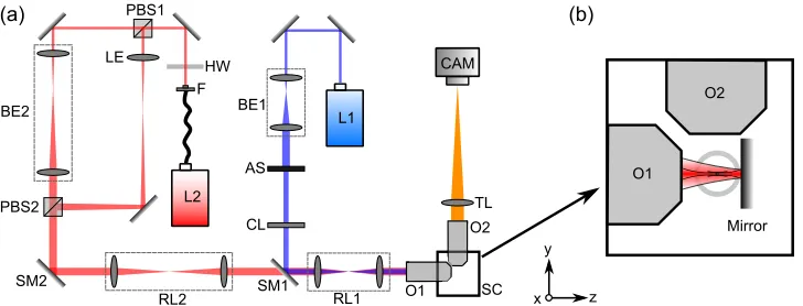
Fig. 1. (a) Optical setup. The right part of the diagram shows the imaging section, which is based on the openSPIM project. The left part of the diagram shows the optics to deliver a near-infrared trapping laser beam into the sample chamber. Colors in the figure illustrate different wavelengths. (b) Enlarged diagram showing the configuration for sample mount-ing in the sample chamber. The sample chamber is filled with water. One of the trappmount-ing beams is reflected by the mirror to achieve a counter-propagating beam configuration. The sample to be imaged and the suspension medium is held in the FEP tube. Not to scale.
Macro-trapping was achieved by integrating a second optical path into the imaging system through a dichroic mirror (SM1, DMLP950, Thorlabs). A near-infrared laser (L2, operating wavelength = 1060 - 1100 nm, 10 W, IPG) is introduced with a fiber (F). The polarization state of the beam is controlled by a half-wave plate (HW, WPH10M-1064, Thorlabs). This enables us to control the laser power distribution between two trapping beams. The beam is split into two by a polarizing beam splitter (PBS1, PBS203, Thorlabs), and then they are combined by another PBS (PBS2). A relay lens combination (RL2, 2×LA1608-C, FL 75 mm, Thorlabs) delivers the beam to the dichroic mirror, then to the illumination objective (O1). In one of the optical paths between the two PBSs, the laser beam is simply expanded (BE2) so that it can fill the back aperture of the illumination objective. In the other optical path, the beam divergence is changed by a lens (LE, LA1608-C, FL 75 mm, Thorlabs) so that the beam is diverging when entering the back aperture of the illumination objective. Those two beams go through the same objective (O1) and focus at two spots on the same axis at a distance of approximately 0.8 mm apart. A silver mirror is used in the sample chamber to retro-reflect the beam to achieve a counter-propagating trap configuration. The distance between the foci is adjustable by translating the mirror along the illumination axis. The spherical aberration introduced by use of the LE lens to refocus the beam is not significant due to the low NA paraxial optics in the setup. In addition, any slight decrease in efficiency due to spherical aberration in the trapping beam can be readily compensated for by adjusting the half-wave plate to supply more power. Hence the imperfection in trapping light path is negligible.
[image:4.612.121.485.125.264.2]upon a manual translation stage (M-562-XYZ, Newport). Figure 1(b) shows the arrangement of the tube and the mirror in the sample chamber (not to scale).
We recorded the trap stiffness for objects placed in this counter-propagating optical mirror trap using the existing detection axis of the light sheet configuration. The camera recorded the position of a trapped 5 µm diameter polystyrene bead over a time period of 10 minutes at a frame rate of 100 Hz. A fiber illuminator (OSL1-EC, Thorlabs) provided extra light during this process. Nine data sets were taken with different laser power, ranging from 18 mW to 43 mW, which was measured at the back aperture of the illumination objective. The bead was located approximately in the middle of the FEP tube. The distance between the two foci was set to about 100 µm. The recorded image sequences gave position trace on the x (lateral on illumination) axis and z (axial on illumination) axis. As the trap is symmetric in the lateral plane, we assumed that trap stiffnesses in the x and y axis directions are similar.
The center of gravity of the trapped 5 µm bead was tracked in the image sequences with Mat-labsoftware. Both equipartition-theorem and power-spectrum approaches [19, 20] were used to measure the trap stiffness. Histograms of the bead position were fitted to a Gaussian dis-tribution to determine trap stiffness with the equipartition-theorem method. These results were then used to design the approach for measuring the stiffness with the more accurate power-spectrum method. The power spectra of the bead position were fitted to a Lorentzian power-spectrum model [20]. To minimize the influence of the noise in the frequency domain, signals with fre-quency components lower than 0.01 Hz and higher than 10 Hz were excluded from the curve fitting.
Biological samples such as tobacco Bright Yellow 2 (BY-2) cells and wild typeS. lamarcki larvae were subsequently trapped and imaged in this system. The BY-2 cell line was originally obtained from The James Hutton Institute (JHI), having been genetically modified to stably express microtubules labeled with GFP.
S. lamarcki adults were collected from East Sands rocks, St Andrews, and maintained in the circulating seawater aquarium system at the Scottish Oceans Institute, Gatty Marine Lab-oratory, at ambient seawater temperature. Larvae were obtained by removing adults from their calcareous habitation tubes by breaking away the posterior of the tube with strong forceps and then pushing the adult worm out of the posterior end of the remaining tube with a blunt probe applied to the anterior end. Individual worms were placed into small volumes (500 µL to 750 µL) of 1.0 µm-filtered seawater in multi-well dishes and allowed to spawn their gametes. Eggs from multiple females were harvested into a Petri dish of filtered seawater and sperm collected separately, with sperm from at least two males being mixed and checked for motil-ity under a microscope. 100 µL of sperm were added to the Petri dish of eggs and fertilization allowed to proceed for 15 minutes at room temperature (less than 22◦C). The eggs were then poured into a 40 µm cell strainer and passed through several changes of fresh filtered seawater to remove excess sperm. Larvae were then left to develop in filtered seawater at approximately 17◦C for 18 hours before imaging.
3. Results
Figure 2 shows an example of the trap stiffness characterization with laser power of 21.7 mW which was measured at the back aperture of the illumination objective. Due to the low NA of the trapping laser beam, the trap stiffness along the axial direction is much lower than for the lateral direction. By averaging the stiffness from the power-spectrum method with different powers, we obtained the power-normalized stiffness ofκx= (2.4±0.11)×10−2pN/µm and
κz= (2.6±0.32)×10−4 pN/µm per mW in the x and z direction, respectively. In addition,
(a)
(b)
(c)
[image:6.612.136.474.80.326.2](d)
(e)
(f)
Fig. 2. An example data set for characterization of the trap stiffness. (a,d) The first 60 seconds of the x- and z- position measurements. (b,e) Histograms of the particle position trace (blue) and the Gaussian fit (red). (c,f) Power spectra of the particle position traces (blue) and the fitted curves (red).
Although some lateral movement and slow rotation of the sample can occur due to the axial stiffness of the trap not being as high as the lateral stiffness, we have found from repeated measurements on various samples that this does not cause a problem for image quality. This is due to the high speed of SPIM, with the sample movement being very slow compared to the image acquisition time.
(a) (b)
Fig. 3. Images of optically trapped tobacco BY-2 cells expressing microtubules labeled with GFP. (a) Bright field image. (b) Maximum intensity projection of light sheet fluo-rescent microscope images of the same cells taken along the z-axis. Scale bar 15 µm. See
Visualization 1for maximum intensity projection video with rotating view angle.
[image:6.612.157.461.479.586.2](CMA-12CCCL, Newport). 400 frames with increments of 0.5 µm at a speed of 8 fps were taken for a complete 3D stack.
Individual S. lamarckilarvae were captured in the trap and their auto-fluorescence signal recorded.S. lamarckilarvae are strong swimmers, moving with a trajectory that normally fol-lows a corkscrew pattern. We observe typical swimming velocities above 1 mm/s at this early stage of development, which is significantly faster than that of the micro-organisms trapped in [16] which moved at 100 µm/s to 150 µm/s. Hence we were able to confine a larva in the trap region, whilst it maintained its rotational motion whilst trying to break through the con-finement of the trap. With the light sheet and detection objective fixed, this rotating movement of the larva enabled us to record section images of it, as shown in Fig. 4. The image shown are of the auto-fluorescence signal present in the larvae rather than a specific immunohisto-chemical or fluorochrome-tagged label, hence they are inevitably of a lower resolution than the completely immobile and GFP-labeled plant cells. As this larva is still at an early stage of development, there is relatively little distinctive morphology to be identified. However, we can readily recognize some structures such as the cilia and invaginating gut.
cilia
cilia
[image:7.612.119.496.269.386.2]invaginating gut
Fig. 4. Images of an optically trappedS. lamarckilarva. (a) Bright field image. (b-d) Three examples of light sheet images, obtained with auto-fluorescent signal from the larva. Ex-ternal (cilia) and inEx-ternal (invaginating gut) structures of the larva can be identified. Scale bar 20 µm. SeeVisualization 2andVisualization 3for corresponding bright field and light sheet imaging videos.
4. Conclusion
Supplementary Information
The research data and materials supporting this publication can be accessed at DOI: 10.17630/8A3DBD39-9AC5-4767-9D99-BDFD0CFAC36A.
Acknowledgments