NONRESIDENT
TRAINING
COURSE
October 1995
Electronics Technician
Volume 7—Antennas and Wave
Propagation
NAVEDTRA 14092
PREFACE
By enrolling in this self-study course, you have demonstrated a desire to improve yourself and the Navy.
Remember, however, this self-study course is only one part of the total Navy training program. Practical
experience, schools, selected reading, and your desire to succeed are also necessary to successfully round
out a fully meaningful training program.
COURSE OVERVIEW: In completing this nonresident training course, you should be able to: discuss
wave propagation in terms of the effects the earth’s atmosphere has on it and the options available to receive
optimum performance from equipment; identify communications and radar antennas using physical
characteristics and installation location, radiation patterns, and power and frequency-handling capabilities.
Be familiar with safety precautions for technicians working aloft; and discuss the different types of
transmission lines in terms of physical structure, frequency limitations, electronic fields, and radiation
losses.
THE COURSE: This self-study course is organized into subject matter areas, each containing learning
objectives to help you determine what you should learn along with text and illustrations to help you
understand the information. The subject matter reflects day-to-day requirements and experiences of
personnel in the rating or skill area. It also reflects guidance provided by Enlisted Community Managers
(ECMs) and other senior personnel, technical references, instructions, etc., and either the occupational or
naval standards, which are listed in the
Manual of Navy Enlisted Manpower Personnel Classifications
and Occupational Standards
, NAVPERS 18068.
THE QUESTIONS: The questions that appear in this course are designed to help you understand the
material in the text.
VALUE:
In completing this course, you will improve your military and professional knowledge.
Importantly, it can also help you study for the Navy-wide advancement in rate examination. If you are
studying and discover a reference in the text to another publication for further information, look it up.
1995 Edition Prepared by
ETC Larry D.Simmons
and
ETC Floyd L.Ace III
Published by
NAVAL EDUCATION AND TRAINING
PROFESSIONAL DEVELOPMENT
AND TECHNOLOGY CENTER
Sailor’s Creed
“
I am a United States Sailor.
I will support and defend the
Constitution of the United States of
America and I will obey the orders
of those appointed over me.
I represent the fighting spirit of the
Navy and those who have gone
before me to defend freedom and
democracy around the world.
I proudly serve my country’s Navy
combat team with honor, courage
and commitment.
CONTENTS
1. Wave Propagation
CHAPTER Page
1-1
2. Antennas 2-1
3-1 3. Introduction to Transmission and Waveguides
APPENDIX
I. Glossary AI-1
II. References AII-1
INDEX Index-1
SUMMARY OF THE ELECTRONICS
TRAINING SERIES
TECHNICIAN
This series of training manuals was developed to replace the Electronics Technician 3 & 2 TRAMAN. The content is directed to personnel working toward advancement to Electronics Technician Second Class.
The nine volumes in the series are based on major topic areas with which the ET2 should be familiar. Volume 1, Safety, provides an introduction to general safety as it relates to the ET rating. It also provides both general and specific information on electronic tag-out procedures, man-aloft procedures, hazardous materials (i.e., solvents, batteries, and vacuum tubes), and radiation hazards. Volume 2, Administration, discusses COSAL updates, 3-M documentation, supply paperwork, and other associated administrative topics. Volume 3, Communication Systems, provides a basic introduction to shipboard and shore-based communication systems. Systems covered include man-pat radios (i.e., PRC-104, PSC-3) in the hf, vhf, uhf, SATCOM, and shf ranges. Also provided is an introduction to the Communications Link Interoperability System (CLIPS). Volume 4, Radar Systems, is a basic introduction to air search, surface search, ground controlled approach, and carrier controlled approach radar systems. Volume 5, Navigation Systems, is a basic introduction to navigation systems, such as OMEGA, SATNAV, TACAN, and man-pat systems. Volume 6, Digital Data Systems, is a basic introduction to digital data systems and includes discussions about SNAP II, laptop computers, and desktop computers. Volume 7, Antennas and Wave Propagation, is an introduction to wave propagation, as it pertains to Electronics Technicians, and shipboard and shore-based antennas. Volume 8, Support Systems, discusses system interfaces, troubleshooting, sub-systems, dry air, cooling, and power systems. Volume 9, Electro-Optics, is an introduction to night vision equipment, lasers, thermal imaging, and fiber optics.
INSTRUCTIONS FOR TAKING THE COURSE
ASSIGNMENTS
The text pages that you are to study are listed at
the beginning of each assignment. Study these
pages carefully before attempting to answer the
questions. Pay close attention to tables and
illustrations and read the learning objectives.
The learning objectives state what you should be
able to do after studying the material. Answering
the questions correctly helps you accomplish the
objectives.
SELECTING YOUR ANSWERS
Read each question carefully, then select the
BEST answer. You may refer freely to the text.
The answers must be the result of your own
work and decisions. You are prohibited from
referring to or copying the answers of others and
from giving answers to anyone else taking the
course.
SUBMITTING YOUR ASSIGNMENTS
To have your assignments graded, you must be
enrolled in the course with the Nonresident
Training Course Administration Branch at the
Naval Education and Training Professional
Development
and
Technology
Center
(NETPDTC). Following enrollment, there are
two ways of having your assignments graded:
(1) use the Internet to submit your assignments
as you complete them, or (2) send all the
assignments at one time by mail to NETPDTC.
Grading on the Internet:
Advantages to
Internet grading are:
•
you may submit your answers as soon as
you complete an assignment, and
•
you get your results faster; usually by the
next working day (approximately 24 hours).
In addition to receiving grade results for each
assignment, you will receive course completion
confirmation once you have completed all the
assignments.
To
submit
your
assignment
answers via the Internet, go to:
http://courses.cnet.navy.mil
Grading by Mail: When you submit answer
sheets by mail, send all of your assignments at
one time. Do NOT submit individual answer
sheets for grading. Mail all of your assignments
in an envelope, which you either provide
yourself or obtain from your nearest Educational
Services Officer (ESO). Submit answer sheets
to:
COMMANDING OFFICER
NETPDTC N331
6490 SAUFLEY FIELD ROAD
PENSACOLA FL 32559-5000
Answer
Sheets:
All
courses
include
one
“scannable” answer sheet for each assignment.
These answer sheets are preprinted with your
SSN, name, assignment number, and course
number. Explanations for completing the answer
sheets are on the answer sheet.
Do not use answer sheet reproductions: Use
only
the
original
answer
sheets
that
we
provide—reproductions will not work with our
scanning equipment and cannot be processed.
Follow the
instructions
for
marking your
answers on the answer sheet. Be sure that blocks
1, 2, and 3 are filled in correctly. This
information is necessary for your course to be
properly processed and for you to receive credit
for your work.
COMPLETION TIME
PASS/FAIL ASSIGNMENT PROCEDURES
If your overall course score is 3.2 or higher, you
will pass the course and will not be required to
resubmit assignments. Once your assignments
have been graded you will receive course
completion confirmation.
If you receive less than a 3.2 on any assignment
and your overall course score is below 3.2, you
will be given the opportunity to resubmit failed
assignments.
You
may
resubmit
failed
assignments only once. Internet students will
receive notification when they have failed an
assignment--they may then resubmit failed
assignments on the web site. Internet students
may
view
and
results
for
failed
assignments from the web site. Students who
submit by mail will receive a failing result letter
and a new answer sheet for resubmission of each
failed assignment.
COMPLETION CONFIRMATION
After successfully completing this course, you
will receive a letter of completion.
ERRATA
Errata are used to correct minor errors or delete
obsolete information in a course.
Errata may
also be used to provide instructions to the
student.
If a course has an errata, it will be
included as the first page(s) after the front cover.
Errata for all courses can be accessed and
viewed/downloaded at:
http://www.advancement.cnet.navy.mil
STUDENT FEEDBACK QUESTIONS
We value your suggestions, questions, and
criticisms on our courses. If you would like to
communicate with us regarding this course, we
encourage you, if possible, to use e-mail. If you
write or fax, please use a copy of the Student
Comment form that follows this page.
For subject matter questions:
E-mail:
[email protected]
Phone:
Comm: (850) 452-1001, Ext. 1713
DSN: 922-1001, Ext. 1713
FAX: (850) 452-1370
(Do not fax answer sheets.)
Address:
COMMANDING OFFICER
NETPDTC N315
6490 SAUFLEY FIELD ROAD
PENSACOLA FL 32509-5237
For
enrollment,
shipping,
grading,
or
completion letter questions
E-mail:
[email protected]
Phone:
Toll Free: 877-264-8583
Comm: (850) 452-1511/1181/1859
DSN: 922-1511/1181/1859
FAX: (850) 452-1370
(Do not fax answer sheets.)
Address:
COMMANDING OFFICER
NETPDTC N331
6490 SAUFLEY FIELD ROAD
PENSACOLA FL 32559-5000
NAVAL RESERVE RETIREMENT CREDIT
Student Comments
Course Title:
Electronics Technician, Volume 7—Antennas and Wave Propagation
NAVEDTRA:
14092
Date:
We need some information about you:
Rate/Rank and Name: SSN: Command/Unit
Street Address: City: State/FPO: Zip
Your comments, suggestions, etc.:
Privacy Act Statement: Under authority of Title 5, USC 301, information regarding your military status is requested in processing your comments and in preparing a reply. This information will not be divulged without written authorization to anyone other than those within DOD for official use in determining performance.
CHAPTER 1
WAVE PROPAGATION
The eyes and ears of a ship or shore station depend on sophisticated, highly computerized electronic systems. The one thing all of these systems have in common is that they lead to and from antennas. Ship’s operators who must communicate, navigate, and be ready to fight the ship 24 hours a day depend on you to keep these emitters and sensors operational.
In this volume, we will review wave propagation, antenna characteristics, shore-based and shipboard communications antennas, matching networks, antenna tuning, radar antennas, antenna safety, transmission lines, connector installation and weatherproofing, waveguides, and waveguide couplings. When you have completed this chapter, you should be able to discuss the basic principles of wave propagation and the atmosphere’s effects on wave propagation.
THE EARTH’S ATMOSPHERE
While radio waves traveling in free space have little outside influence to affect them, radio waves traveling in the earth’s atmosphere have many influences that affect them. We have all experienced problems with radio waves, caused by certain atmospheric conditions complicating what at first seemed to be a relatively simple electronic problem. These problem-causing conditions result from a lack of uniformity in the earth’s atmosphere.
Many factors can affect atmospheric conditions, either positively or negatively. Three of these are variations in geographic height, differences in geographic location, and changes in time (day, night, season, year).
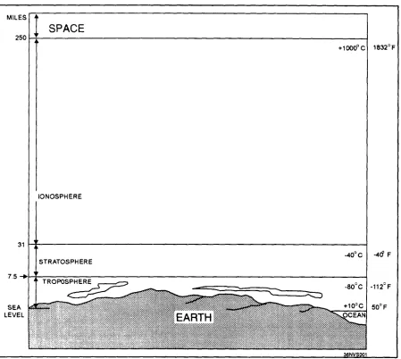
To understand wave propagation, you must have at least a basic understanding of the earth’s atmosphere. The earth’s atmosphere is divided into three separate regions, or layers. They are the troposphere, the stratosphere, and the ionosphere. These layers are illustrated in figure 1-1.
TROPOSPHERE
Almost all weather phenomena take place in the troposphere. The temperature in this region decreases rapidly with altitude. Clouds form, and there may be a lot of turbulence because of variations in the temperature, pressure, and density. These conditions have a profound effect on the propagation of radio waves, as we will explain later in this chapter.
STRATOSPHERE
The stratosphere is located between the troposphere and the ionosphere. The temperature throughout this region is almost constant and there is little water vapor present. Because it is a relatively calm region with little or no temperature change, the stratosphere has almost no effect on radio waves.
IONOSPHERE
This is the most important region of the earth’s atmosphere for long distance, point-to-point communi-cations. Because the existence of the ionosphere is directly related to radiation emitted from the sun, the movement of the earth about the sun or changes in the sun’s activity will result in variations in the ionosphere. These variations are of two general types: (1) those that more or less occur in cycles and, therefore, can be predicted with reasonable accuracy; and (2) those that are irregular as a result of abnormal behavior of the sun and, therefore, cannot be predicted. Both regular and irregular variations have important effects on radio-wave propagation. Since irregular variations cannot be predicted, we will concentrate on regular variations.
Regular Variations
Figure 1.1—Atmospheric layers.
since they have the greatest effect on your job. Daily of the ultraviolet energy that initially set them free variations in the ionosphere produce four cloud-like
layers of electrically-charged gas atoms called ions, which enable radio waves to be propagated great distances around the earth. Ions are formed by a process called ionization.
Ionization
In ionization, high-energy ultraviolet light waves from the sun periodically enter the ionosphere, strike neutral gas atoms, and knock one or more electrons free from each atom. When the electrons are knocked free, the atoms become positively charged (positive
ions) and remain in space, along with the
negatively-charged free electrons. The free electrons absorb some
and form an ionized layer.
Since the atmosphere is bombarded by ultraviolet waves of differing frequencies, several ionized layers are formed at different altitudes. Ultraviolet waves of higher frequencies penetrate the most, so they produce ionized layers in the lower portion of the ionosphere. Conversely, ultraviolet waves of lower frequencies penetrate the least, so they form layers in the upper regions of the ionosphere.
on the time of day and the season of the year. Another important factor in determining layer density is known as recombination.
Recombination
Recombination is the reverse process of ionization. It occurs when free electrons and positive ions collide, combine, and return the positive ions to their original neutral state.
Like ionization, the recombination process depends on the time of day. Between early morning and late afternoon, the rate of ionization exceeds the rate of recombination. During this period the ionized layers reach their greatest density and exert maximum influence on radio waves. However, during the late afternoon and early evening, the rate of recombination exceeds the rate of ionization, causing the densities of the ionized layers to decrease. Throughout the night, density continues to decrease, reaching its lowest point just before sunrise. It is important to understand that this ionization and recombination process varies, depending on the ionospheric layer and the time of day. The following paragraphs provide an explanation of the four ionospheric layers.
Ionospheric Layers
The ionosphere is composed of three distinct layers, designated from lowest level to highest level
(D, E, and F) as shown in figure 1-2. In addition, the
F layer is divided into two layers, designated F1 (the
lower level) and F2 (the higher level).
The presence or absence of these layers in the ionosphere and their height above the earth vary with the position of the sun. At high noon, radiation in the ionosphere above a given point is greatest, while at night it is minimum. When the radiation is removed, many of the particles that were ionized recombine. During the time between these two conditions, the position and number of ionized layers within the ionosphere change.
Since the position of the sun varies daily, monthly, and yearly with respect to a specific point on earth, the exact number of layers present is extremely difficult to determine. However, the following general statements about these layers can be made.
D LAYER.— The D layer ranges from about 30
[image:13.612.136.488.471.676.2]to 55 miles above the earth. Ionization in the D layer is low because less ultraviolet light penetrates to this level. At very low frequencies, the D layer and the ground act as a huge waveguide, making communica-tion possible only with large antennas and high-power transmitters. At low and medium frequencies, the D layer becomes highly absorptive, which limits the effective daytime communication range to about 200 miles. At frequencies above about 3 MHz, the D layer begins to lose its absorptive qualities.
Long-distance communication is possible at frequencies as high as 30 MHz. Waves at frequencies above this range pass through the D layer but are attenuated. After sunset. the D layer disappears because of the rapid recombination of ions. Low-frequency and medium-Low-frequency long-distance communication becomes possible. This is why AM behaves so differently at night. Signals passing through the D layer normally are not absorbed but are propagated by the E and F layers.
E LAYER.— The E layer ranges from
approxi-mately 55 to 90 miles above the earth. The rate of ionospheric recombination in this layer is rather rapid after sunset, causing it to nearly disappear by midnight. The E layer permits medium-range communications on the low-frequency through very-high-frequency bands. At frequencies above about 150 MHz, radio waves pass through the E layer.
Sometimes a solar flare will cause this layer to ionize at night over specific areas. Propagation in this layer during this time is called SPORADIC-E. The range of communication in sporadic-E often exceeds 1000 miles, but the range is not as great as with F layer propagation.
F LAYER.— The F layer exists from about 90 to
240 miles above the earth. During daylight hours, the
F layer separates into two layers, F1 and F2. During
the night, the F1 layer usually disappears, The F layer produces maximum ionization during the afternoon hours, but the effects of the daily cycle are not as pronounced as in the D and E layers. Atoms in the F layer stay ionized for a longer time after sunset, and during maximum sunspot activity, they can stay ionized all night long.
Since the F layer is the highest of the ionospheric layers, it also has the longest propagation capability. For horizontal waves, the single-hop F2 distance can reach 3000 miles. For signals to propagate over greater distances, multiple hops are required.
The F layer is responsible for most high-frequency, long-distance communications. The maximum frequency that the F layer will return depends on the degree of sunspot activity. During maximum sunspot activity, the F layer can return
signals at frequencies as high as 100 MHz. During minimum sunspot activity, the maximum usable frequency can drop to as low as 10 MHz.
ATMOSPHERIC PROPAGATION
Within the atmosphere, radio waves can be refracted, reflected, and diffracted. In the following paragraphs, we will discuss these propagation characteristics.
REFRACTION
A radio wave transmitted into ionized layers is always refracted, or bent. This bending of radio waves is called refraction. Notice the radio wave shown in figure 1-3, traveling through the earth’s atmosphere at a constant speed. As the wave enters the denser layer of charged ions, its upper portion moves faster than its lower portion. The abrupt speed increase of the upper part of the wave causes it to bend back toward the earth. This bending is always toward the propagation medium where the radio wave’s velocity is the least.
Figure 1-3.—Radio-wave refraction.
The amount of refraction a radio wave undergoes depends on three main factors.
1. The ionization density of the layer 2. The frequency of the radio wave
Figure 1-4.—Effects of ionospheric density on radio waves.
Layer Density
Figure 1-4 shows the relationship between radio waves and ionization density. Each ionized layer has a middle region of relatively dense ionization with less intensity above and below. As a radio wave enters a region of increasing ionization, a velocity increase causes it to bend back toward the earth. In the highly dense middle region, refraction occurs more slowly because the ionization density is uniform. As the wave enters the upper less dense region, the velocity of the upper part of the wave decreases and the wave is bent away from the earth.
Frequency
The lower the frequency of a radio wave, the more rapidly the wave is refracted by a given degree of ionization. Figure 1-5 shows three separate waves of differing frequencies entering the ionosphere at the same angle. You can see that the 5-MHz wave is refracted quite sharply, while the 20-MHz wave is refracted less sharply and returns to earth at a greater distance than the 5-MHz wave. Notice that the 100-5-MHz wave is lost
into space. For any given ionized layer, there is a frequency, called the escape point, at which energy transmitted directly upward will escape into space. The maximum frequency just below the escape point is called the critical frequency. In this example, the 100-MHz wave’s frequency is greater than the critical frequency for that ionized layer.
Figure 1-5.—Frequency versus refraction and distance.
particular layer, it may still be refracted by a higher layer if its frequency is lower than the higher layer’s critical frequency.
Angle of Incidence and Critical Angle
When a radio wave encounters a layer of the ionosphere, that wave is returned to earth at the same angle (roughly) as its angle of incidence. Figure 1-6 shows three radio waves of the same frequency entering a layer at different incidence angles. The angle at which wave A strikes the layer is too nearly vertical for the wave to be refracted to earth, However, wave B is refracted back to earth. The angle between wave B and the earth is called the critical angle. Any wave, at a given frequency, that leaves the antenna at an incidence angle greater than the critical angle will be lost into space. This is why wave A was not refracted. Wave C leaves the antenna at the smallest angle that will allow it to be refracted and still return to earth. The critical angle for radio waves depends on the layer density and the wavelength of the signal.
Figure 1-6.—Incidence angles of radio waves.
As the frequency of a radio wave is increased, the critical angle must be reduced for refraction to occur. Notice in figure 1-7 that the 2-MHz wave strikes the ionosphere at the critical angle for that frequency and is refracted. Although the 5-MHz line (broken line) strikes the ionosphere at a less critical angle, it still penetrates the layer and is lost As the angle is lowered, a critical angle is finally reached for the 5-MHz wave and it is refracted back to earth.
SKIP DISTANCE AND ZONE
Recall from your previous study that a transmitted radio wave separates into two parts, the sky wave and the ground wave. With those two components in mind, we will now briefly discuss skip distance and skip zone.
Skip Distance
Look at the relationship between the sky wave skip distance, skip zone, and ground wave coverage shown in figure 1-8. The skip distance is the distance from the transmitter to the point where the sky wave first returns to the earth. The skip distance depends on the wave’s frequency and angle of incidence, and the degree of ionization.
Figure 1-8.—Relationship between skip zone, skip distance, and ground wave.
Skip Zone
The skip zone is a zone of silence between the point where the ground wave is too weak for reception and the point where the sky wave is first returned to earth. The outer limit of the skip zone varies considerably, depending on the operating frequency, the time of day, the season of the year, sunspot activity, and the direction of transmission. At very-low, low, and medium frequencies, a skip zone is never present. However, in the high-frequency spectrum, a skip zone is often present. As the operating frequency is increased, the skip zone widens to a point where the outer limit of the skip zone might be several thousand miles away. At frequencies above a certain maximum, the outer limit of the skip zone disappears completely, and no F-layer propagation is possible.
Occasionally, the first sky wave will return to earth within the range of the ground wave. In this case, severe fading can result from the phase difference between the two waves (the sky wave has a longer path to follow).
REFLECTION
Reflection occurs when radio waves are “bounced” from a flat surface. There are basically two types of reflection that occur in the atmosphere: earth reflection and ionospheric reflection. Figure 1-9 shows two
waves reflected from the earth’s surface. Waves A and B bounce off the earth’s surface like light off of a mirror. Notice that the positive and negative alternations of radio waves A and B are in phase before they strike the earth’s surface. However, after reflection the radio waves are approximately 180 degrees out of phase. A phase shift has occurred.
The amount of phase shift that occurs is not constant. It varies, depending on the wave polarization and the angle at which the wave strikes the surface. Because reflection is not constant, fading occurs. Normally, radio waves reflected in phase produce stronger signals, while those reflected out of phase produce a weak or fading signal.
Ionospheric reflection occurs when certain radio waves strike a thin, highly ionized layer in the ionosphere. Although the radio waves are actually refracted, some may be bent back so rapidly that they appear to be reflected. For ionospheric reflection to occur, the highly ionized layer can be approximately no thicker than one wavelength of the wave. Since the ionized layers are often several miles thick, ionospheric reflection mostly occurs at long wave-lengths (low frequencies).
DIFFRACTION
Diffraction is the ability of radio waves to turn sharp corners and bend around obstacles. Shown in figure 1-10, diffraction results in a change of direction of part of the radio-wave energy around the edges of an obstacle. Radio waves with long wavelengths compared to the diameter of an obstruction are easily propagated around the obstruction. However, as the wavelength decreases, the obstruction causes more and more attenuation, until at very-high frequencies a definite shadow zone develops. The shadow zone is basically a blank area on the opposite side of an obstruction in line-of-sight from the transmitter to the receiver.
Diffraction can extend the radio range beyond the horizon. By using high power and low-frequencies, radio waves can be made to encircle the earth by diffraction.
Figure 1-10.—Diffraction around an object.
ATMOSPHERIC EFFECTS ON PROPAGATION
As we stated earlier, changes in the ionosphere can produce dramatic changes in the ability to communicate. In some cases, communications distances are greatly extended. In other cases, communications distances are greatly reduced or eliminated. The paragraphs below explain the major problem of reduced communications because of the phenomena of fading and selective fading.
Fading
The most troublesome and frustrating problem in receiving radio signals is variations in signal strength, most commonly known as FADING. Several conditions can produce fading. When a radio wave is refracted by the ionosphere or reflected from the earth’s surface, random changes in the polarization of the wave may occur. Vertically and horizontally mounted receiving antennas are designed to receive vertically and horizontally polarized waves, respec-tively. Therefore, changes in polarization cause changes in the received signal level because of the inability of the antenna to receive polarization changes.
density is the greatest. As a radio wave passes into the ionosphere, it loses some of its energy to the free electrons and ions present there. Since the amount of absorption of the radio-wave energy varies with the density of the ionospheric layers, there is no fixed relationship between distance and signal strength for ionospheric propagation. Absorption fading occurs for a longer period than other types of fading, since absorption takes place slowly. Under certain conditions, the absorption of energy is so great that communication over any distance beyond the line of sight becomes difficult.
Although fading because of absorption is the most serious type of fading, fading on the ionospheric circuits is mainly a result of multipath propagation.
Multipath Fading
MULTIPATH is simply a term used to describe
the multiple paths a radio wave may follow between transmitter and receiver. Such propagation paths include the ground wave, ionospheric refraction, reradiation by the ionospheric layers, reflection from the earth’s surface or from more than one ionospheric layer, and so on. Figure 1-11 shows a few of the paths that a signal can travel between two sites in a typical circuit. One path, XYZ, is the basic ground wave. Another path, XFZ, refracts the wave at the F layer and passes it on to the receiver at point Z. At point Z, the received signal is a combination of the ground wave and the sky wave. These two signals, having traveled different paths, arrive at point Z at different times. Thus, the arriving waves may or may not be in phase with each other. A similar situation may result at point A. Another path, XFZFA, results from a greater angle of incidence and two refractions from the F layer. A wave traveling that path and one traveling the XEA path may or may not arrive at point A in phase. Radio waves that are received in phase reinforce each other and produce a stronger signal at the receiving site, while those that are received out of phase produce a weak or fading signal. Small alterations in the transmission path may change the phase relationship of the two signals, causing periodic fading.
Figure 1-11.—Multipath transmission.
Multipath fading may be minimized by practices called SPACE DIVERSITY and FREQUENCY DIVERSITY In space diversity, two or more receiving antennas are spaced some distance apart. Fading does not occur simultaneously at both antennas. Therefore, enough output is almost always available from one of the antennas to provide a useful signal.
In frequency diversity, two transmitters and two receivers are used, each pair tuned to a different frequency, with the same information being transmitted simultaneously over both frequencies. One of the two receivers will almost always produce a useful signal.
Selective Fading
Fading resulting from multipath propagation varies with frequency since each frequency arrives at the
receiving point via a different radio path. When a wide band of frequencies is transmitted simultaneously,
each frequency will vary in the amount of fading. This variation is called SELECTIVE FADING. When selective fading occurs, all frequencies of the transmitted signal do not retain their original phases and relative amplitudes. This fading causes severe distortion of the signal and limits the total signal transmitted.
Table 1-1.–Daily Ionospheric Communications
D LAYER: reflects vlf waves for long-range
communications; refracts lf and mf for
short-range communications; has little
effect on vhf and above; gone at night.
E LAYER: depends on the angle of the sun:
refracts hf waves during the day up to 20
MHz to distances of 1200 miles: greatly
reduced at night.
F LAYER: structure and density depend on
the time of day and the angle of the sun:
consists of one layer at night and splits
into two layers during daylight hours.
F1 LAYER: density depends on the angle of
the sun; its main effect is to absorb hf
waves passing through to the F2 layer.
F2 LAYER: provides long-range hf
communica-tions; very variable; height and density
change with time of day, season, and
sun-spot activity.
Figure 1-12.—Ionospheric layers.
OTHER PHENOMENA THAT AFFECT of these layers is greatest during the summer. The
COMMUNICATIONS F2 layer is just the opposite. Its ionization is greatest during the winter, Therefore, operating frequencies Although daily changes in the ionosphere have for F2 layer propagation are higher in the winter than the greatest effect on communications, other
phenom-ena also affect communications, both positively and negatively. Those phenomena are discussed briefly in the following paragraphs.
SEASONAL VARIATIONS IN THE IONOSPHERE
Seasonal variations are the result of the earth’s revolving around the sun, because the relative position of the sun moves from one hemisphere to the other with the changes in seasons. Seasonal variations of the D, E, and F1 layers are directly related to the highest angle of the sun, meaning the ionization density
in the summer.
SUNSPOTS
One of the most notable occurrences on the surface of the sun is the appearance and disappearance of dark, irregularly shaped areas known as SUNSPOTS. Sunspots are believed to be caused by violent eruptions on the sun and are characterized by strong magnetic fields. These sunspots cause variations in the ionization level of the ionosphere.
Twenty-Seven Day Cycle
The number of sunspots present at any one time is constantly changing as some disappear and new ones emerge. As the sun rotates on its own axis, these sunspots are visible at 27-day intervals, which is the approximate period for the sun to make one complete revolution. During this time period, the fluctuations in ionization are greatest in the F2 layer. For this reason, calculating critical frequencies for long-distance communications for the F2 layer is not possible and allowances for fluctuations must be made.
Eleven-Year Cycle
Sunspots can occur unexpectedly, and the life span of individual sunspots is variable. The ELEVEN-YEAR SUN SPOT CYCLE is a regular cycle of sunspot activity that has a minimum and maximum level of activity that occurs every 11 years. During periods of maximum activity, the ionization density of all the layers increases. Because of this, the absorption in the D layer increases and the critical frequencies for the E, F1, and F2 layers are higher. During these times, higher operating frequencies must be used for long-range communications.
IRREGULAR VARIATIONS
Irregular variations are just that, unpredictable changes in the ionosphere that can drastically affect our ability to communicate. The more common variations are sporadic E, ionospheric disturbances, and ionospheric storms.
Sporadic E
Irregular cloud-like patches of unusually high ionization, called the sporadic E, often format heights near the normal E layer. Their exact cause is not known and their occurrence cannot be predicted. However, sporadic E is known to vary significantly with latitude. In the northern latitudes, it appears to be closely related to the aurora borealis or northern lights.
The sporadic E layer can be so thin that radio waves penetrate it easily and are returned to earth by the upper layers, or it can be heavily ionized and
extend up to several hundred miles into the ionosphere. This condition may be either harmful or helpful to radio-wave propagation.
On the harmful side, sporadic E may blank out the use of higher more favorable layers or cause additional absorption of radio waves at some frequen-cies. It can also cause additional multipath problems and delay the arrival times of the rays of RF energy.
On the helpful side, the critical frequency of the sporadic E can be greater than double the critical frequency of the normal ionospheric layers. This may permit long-distance communications with unusually high frequencies. It may also permit short-distance communications to locations that would normally be in the skip zone.
Sporadic E can appear and disappear in a short time during the day or night and usually does not occur at same time for all transmitting or receiving stations.
Sudden Ionospheric Disturbances
Commonly known as SID, these disturbances may occur without warning and may last for a few minutes to several hours. When SID occurs, long-range hf communications are almost totally blanked out. The radio operator listening during this time will believe his or her receiver has gone dead.
The occurrence of SID is caused by a bright solar eruption producing an unusually intense burst of ultraviolet light that is not absorbed by the F1, F2, or E layers. Instead, it causes the D-layer ionization density to greatly increase. As a result, frequencies above 1 or 2 megahertz are unable to penetrate the D layer and are completely absorbed.
Ionospheric Storms
normal. What this means for communication purposes is that the range of frequencies on a given circuit is smaller than normal and that communications are possible only at lower working frequencies.
Weather
Wind, air temperature, and water content of the atmosphere can combine either to extend radio communications or to greatly attenuate wave propaga-tion. making normal communications extremely difficult. Precipitation in the atmosphere has its greatest effect on the higher frequency ranges. Frequencies in the hf range and below show little effect from this condition.
RAIN.— Attenuation because of raindrops is greater
than attenuation for any other form of precipitation. Raindrop attenuation may be caused either by absorption, where the raindrop acts as a poor dielectric, absorbs power from the radio wave and dissipates the power by heat loss; or by scattering (fig. 1-13). Raindrops cause greater attenuation by scattering than by absorption at frequencies above 100 megahertz. At frequencies above 6 gigahertz, attenuation by raindrop scatter is even greater.
Figure 1-13.–Rf energy losses from scattering.
FOG.— Since fog remains suspended in the
atmosphere, the attenuation is determined by the quantity of water per unit volume (density of the fog) and by the size of the droplets. Attenuation because of fog has little effect on frequencies lower than 2 gigahertz, but can cause serious attenuation by absorption at frequencies above 2 gigahertz.
SNOW.— Since snow has about 1/8 the density
of rain, and because of the irregular shape of the
snowflake, the scattering and absorption losses are difficult to compute, but will be less than those caused by raindrops.
HAIL.— Attenuation by hail is determined by the
size of the stones and their density. Attenuation of radio waves by scattering because of hailstones is considerably less than by rain.
TEMPERATURE INVERSION
When layers of warm air form above layers of cold air, the condition known as temperature inversion develops. This phenomenon causes ducts or channels to be formed, by sandwiching cool air either between the surface of the earth and a layer of warm air, or between two layers of warm air. If a transmitting antenna extends into such a duct, or if the radio wave enters the duct at a very low angle of incidence, vhf and uhf transmissions may be propagated far beyond normal line-of-sight distances. These long distances are possible because of the different densities and refractive qualities of warm and cool air. The sudden change in densities when a radio wave enters the warm air above the duct causes the wave to be refracted back toward earth. When the wave strikes the earth or a warm layer below the duct, it is again reflected or refracted upward and proceeds on through the duct with a multiple-hop type of action. An example of radio-wave propagation by ducting is shown in figure
1-14.
Figure 1-14.—Duct effect caused by temperature inversion.
TRANSMISSION LOSSES
atmospheric levels in the ionosphere account for a large part of these energy losses. There are two other types of losses that also significantly affect propagation. These losses are known as ground
reflection losses and freespace loss. The combined
effect of absorption ground reflection loss, and freespace loss account for most of the losses of radio transmissions propagated in the ionosphere.
GROUND REFLECTION LOSS
When propagation is accomplished via multihop refraction, rf energy is lost each time the radio wave is reflected from the earth’s surface. The amount of energy lost depends on the frequency of the wave, the angle of incidence, ground irregularities, and the electrical conductivity of the point of reflection.
FREESPACE LOSS
Normally, the major loss of energy is because of the spreading out of the wavefront as it travels from the transmitter. As distance increases, the area of the wavefront spreads out, much like the beam of a flashlight. This means the amount of energy contained within any unit of area on the wavefront decreases as distance increases. By the time the energy arrives at the receiving antenna, the wavefront is so spread out that the receiving antenna extends into only a small portion of the wavefront. This is illustrated in figure 1-15.
FREQUENCY SELECTION
You must have a thorough knowledge of radio-wave propagation to exercise good judgment when selecting transmitting and receiving antennas and operating frequencies. Selecting a usable operating frequency within your given allocations and availability is of prime importance to maintaining reliable communications.
For successful communication between any two specified locations at any given time of the day, there is a maximum frequency, a lowest frequency and an optimum frequency that can be used.
Figure 1-15.—Freespace loss principle.
MAXIMUM USABLE FREQUENCY
The higher the frequency of a radio wave, the lower the rate of refraction by the ionosphere. Therefore, for a given angle of incidence and time of day, there is a maximum frequency that can be used for communications between two given locations. This frequency is known as the MAXIMUM USABLE
FREQUENCY (muf).
Waves at frequencies above the muf are normally refracted so slowly that they return to earth beyond the desired location or pass on through the ionosphere and are lost. Variations in the ionosphere that can raise or lower a predetermined muf may occur at anytime. his is especially true for the highly variable F2 layer.
LOWEST USABLE FREQUENCY
Figure 1-16.—Refraction of frequencies below the lowest usable frequency (luf).
As a frequency is lowered, absorption of the radio wave increases. A wave whose frequency is too low is absorbed to such an extent that it is too weak for reception. Atmospheric noise is also greater at lower frequencies. A combination of higher absorption and atmospheric noise could result in an unacceptable signal-to-noise ratio.
For a given angle ionospheric conditions, of incidence and set of the luf depends on the refraction
properties of the ionosphere, absorption considerations, and the amount of noise present.
OPTIMUM WORKING FREQUENCY
The most practical operating frequency is one that you can rely onto have the least number of problems. It should be high enough to avoid the problems of multipath fading, absorption, and noise encountered at the lower frequencies; but not so high as to be affected by the adverse effects of rapid changes in the ionosphere.
A frequency that meets the above criteria is known as the OPTIMUM WORKING FREQUENCY It is abbreviated “fot” from the initial letters of the French words for optimum working frequency, “frequence optimum de travail.” The fot is roughly about 85% of the muf, but the actual percentage varies and may be considerably more or less than 85 percent.
CHAPTER 2
ANTENNAS
As an Electronics Technician, you are responsible for maintaining systems that both radiate and receive electromagnetic energy. Each of these systems requires some type of antenna to make use of this electromag-netic energy. In this chapter we will discuss antenna characteristics, different antenna types, antenna tuning, and antenna safety.
ANTENNA CHARACTERISTICS
An antenna may be defined as a conductor or group of conductors used either for radiating electromagnetic energy into space or for collecting it from space. Electrical energy from the transmitter is converted into electromagnetic energy by the antenna and radiated into space. On the receiving end, electromagnetic energy is converted into electrical energy by the antenna and fed into the receiver.
The electromagnetic radiation from an antenna is made up of two components, the E field and the H field. The total energy in the radiated wave remains constant in space except for some absorption of energy by the earth. However, as the wave advances, the energy spreads out over a greater area. This causes the amount of energy in a given area to decrease as distance from the source increases.
The design of the antenna system is very important in a transmitting station. The antenna must be able to radiate efficiently so the power supplied by the transmitter is not wasted. An efficient transmitting antenna must have exact dimensions, determined by the frequency being transmitted. The dimensions of the receiving antenna are not critical for relatively low frequencies, but their importance increases drastically as the transmitted frequency increases.
Most practical transmitting antennas are divided into two basic classifications, HERTZ ANTENNAS (half-wave) and MARCONI (quarter-wave) ANTEN-NAS. Hertz antennas are generally installed some distance above the ground and are positioned to radiate
either vertically or horizontally. Marconi antennas operate with one end grounded and are mounted perpendicular to the earth or a surface acting as a ground. The Hertz antenna, also referred to as a dipole, is the basis for some of the more complex antenna systems used today. Hertz antennas are generally used for operating frequencies of 2 MHz and above, while Marconi antennas are used for operating frequencies below 2 MHz.
All antennas, regardless of their shape or size, have four basic characteristics: reciprocity, directivity, gain, and polarization.
RECIPROCITY
RECIPROCITY is the ability to use the same antenna for both transmitting and receiving. The electrical characteristics of an antenna apply equally, regardless of whether you use the antenna for transmitting or receiving. The more efficient an antenna is for transmitting a certain frequency, the more efficient it will be as a receiving antenna for the same frequency. This is illustrated by figure 2-1, view A. When the antenna is used for transmitting, maximum radiation occurs at right angles to its axis. When the same antenna is used for receiving (view B), its best reception is along the same path; that is, at right angles to the axis of the antenna.
DIRECTIVITY
Figure 2-1.—Reciprocity of antennas.
elements can be considered fed from a common source.
GAIN
as a group of antennas
As we mentioned earlier, some antennas are highly directional. That is, they propagate more energy in certain directions than in others. The ratio between the amount of energy propagated in these directions and the energy that would be propagated if the antenna were not directional is known as antenna GAIN. The gain of an antenna is constant. whether the antenna is used for transmitting or receiving.
POLARIZATION
Energy from an antenna is radiated in the form of an expanding sphere. A small section of this sphere is called a wavefront. positioned perpendicular to the direction of the radiation field (fig. 2-2). Within this wavefront. all energy is in phase. Usually, all points on the wavefront are an equal distance from the antenna. The farther from the antenna the wave is, the less curved it appears. At a considerable distance, the wavefront can be considered as a plane surface
at right angles to the direction of propagation.
Figure 2-2.—Horizontal and vertical polarization.
The radiation field is made up of magnetic and electric lines of force that are always at right angles to each other. Most electromagnetic fields in space are said to be linearly polarized. The direction of polarization is the direction of the electric vector. That is, if the electric lines of force (E lines) are horizontal, the wave is said to be horizontally polarized (fig. 2-2), and if the E lines are vertical, the wave is said to be vertically polarized. Since the electric field is parallel to the axis of the dipole, the antenna is in the plane of polarization.
A horizontally placed antenna produces a horizon-tally polarized wave, and a vertically placed antenna produces a vertically polarized wave.
In general, the polarization of a wave does not change over short distances. Therefore, transmitting and receiving antennas are oriented alike, especially if they are separated by short distances.
When the transmitting antenna is close to the ground, it should be polarized vertically, because vertically polarized waves produce a greater signal strength along the earth’s surface. On the other hand, when the transmitting antenna is high above the ground, it should be horizontally polarized to get the greatest signal strength possible to the earth’s surface.
RADIATION OF ELECTROMAGNETIC ENERGY
Various factors in the antenna circuit affect the radiation of electromagnetic energy. In figure 2-3, for example, if an alternating current is applied to the A end of wire antenna AB, the wave will travel along the wire until it reaches the B end. Since the B end is free, an open circuit exists and the wave cannot travel further. This is a point of high impedance. The wave bounces back (reflects) from this point of high impedance and travels toward the starting point, where it is again reflected. Theoretically, the energy of the wave should be gradually dissipated by the resistance of the wire during this back-and-forth motion (oscillation). However, each time the wave reaches the starting point, it is reinforced by an impulse of energy sufficient to replace the energy lost during its travel along the wire. This results in continuous oscillations of energy along the wire and a high voltage at the A end of the wire. These oscillations move along the antenna at a rate equal to the frequency of the rf voltage and are sustained by properly timed impulses at point A.
Figure 2-3.—Antenna and rf source.
The rate at which the wave travels along the wire is constant at approximately 300,000,000 meters per second. The length of the antenna must be such that a wave will travel from one end to the other and back again during the period of 1 cycle of the rf voltage.
The distance the wave travels during the period of 1 cycle is known as the wavelength. It is found by dividing the rate of travel by the frequency.
Look at the current and voltage distribution on the antenna in figure 2-4. A maximum movement of electrons is in the center of the antenna at all times; therefore, the center of the antenna is at a low impedance.
Figure 2-4.—Standing waves of current and voltage on an antenna.
the resultant voltage and current loops and nodes. The presence of standing waves describes the condition of resonance in an antenna. At resonance, the waves travel back and forth in the antenna, reinforcing each other, and are transmitted into space at maximum radiation. When the antenna is not at resonance, the waves tend to cancel each other and energy is lost in the form of heat.
RADIATION TYPES AND PATTERNS
A logical assumption is that energy leaving an antenna radiates equally over 360 degrees. This is not the case for every antenna.
The energy radiated from an antenna forms a field having a definite RADIATION PATTERN. The radiation pattern for any given antenna is determined by measuring the radiated energy at various angles at constant distances from the antenna and then plotting the energy values on a graph. The shape of this pattern depends on the type of antenna being used.
Some antennas radiate energy equally in all directions. Radiation of this type is known as ISOTROPIC RADIATION. The sun is a good example of an isotropic radiator. If you were to measure the amount of radiated energy around the sun’s circumference, the readings would all be fairly equal (fig. 2-5).
Most radiators emit (radiate) energy more strongly in one direction than in another. These radiators are referred to as ANISOTROPIC radiators. A flashlight is a good example of an anisotropic radiator (fig. 2-6). The beam of the flashlight lights only a portion of the space surrounding it. The area behind the flashlight remains unlit, while the area in front and to either side is illuminated.
MAJOR AND MINOR LOBES
The pattern shown in figure 2-7, view B, has radiation concentrated in two lobes. The radiation intensity in one lobe is considerably stronger than in the other. The lobe toward point X is called a MAJOR LOBE; the other is a MINOR LOBE. Since the complex radiation patterns associated with antennas frequently contain several lobes of varying intensity,
Figure 2-5.—Isotropic radiation graphs.
you should learn to use the appropriate terminology, In general, major lobes are those in which the greatest amount of radiation occurs. Minor lobes are those in which the least amount of radiation occurs.
ANTENNA LOADING
Figure 2-6.—Anisotropic radiator.
resonance. Changing the antenna dimensions physically is impractical, but changing them electrically is relatively simple. To change the electrical length of an antenna, you can insert either an inductor or a capacitor in series with the antenna. This is shown in figure 2-8, views A and B. Changing the electrical length by this method is known as LUMPED-IMPEDANCE TUNING or LOADING. If the antenna is too short for the wavelength being used, it will be resonant at a higher frequency. Therefore, it offers a capacitive reactance at the excitation frequency. This capacitive reactance can be compensated for by introducing a lumped inductive reactance, as shown in view A. Similarly, if the
Figure 2-7.—Major and minor lobes.
antenna is too long for the transmitting frequency, it will be resonant at a lower frequency and offers an inductive reactance. Inductive reactance can be compensated for by introducing a lumped capacitive reactance, as shown in view B. An antenna with normal loading is represented in view C.
Figure 2-8.—Electrical antenna loading.
GROUND EFFECTS
COMMUNICATIONS ANTENNAS
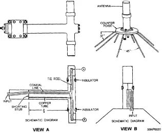
Figure 2-9.—Ground screen and counterpoise.
The ground screen in view A is composed of a series of conductors arranged in a radial pattern and buried 1 or 2 feet below the surface of the earth. These conductors, each usually 1/2 wavelength long, reduce ground absorption losses in the vicinity of the antenna.
A counterpoise (view B) is used when easy access to the base of the antenna is necessary. It is also used when the area below the antenna is not a good conducting surface, such as solid rock or ground that is sandy. The counterpoise serves the same purpose as the ground screen but is usually elevated above the earth. No specific dimensions are necessary for a counterpoise, nor is the number of wires particularly critical. The primary requirement is that the counter-poise be insulated from ground and form a grid of reflector elements for the antenna system.
Some antennas can be used in both shore-based and ship-based applications. Others, however, are designed to be used primarily in one application or the other. The following paragraphs discuss, by frequency range, antennas used for shore-based communications.
VERY LOW FREQUENCY (VLF)
The main difficulty in vlf and lf antenna design is the physical disparity between the maximum practical size of the antenna and the wavelength of the frequency it must propagate. These antennas must be large to compensate for wavelength and power handling requirements (0.25 to 2 MW), Transmitting antennas for vlf have multiple towers 600 to 1500 feet high, an extensive flat top for capacitive load-ing, and a copper ground system for reducing ground losses. Capacitive top-loading increases the bandwidth characteristics, while the ground plane improves radiation efficiency.
Representative antenna configurations are shown in figures 2-10 through 2-12. Variations of these basic antennas are used at the majority of the Navy vlf sites.
Figure 2-12.—Trideco-type antenna.
Figure 2-11.—Goliath-type antenna.
HIGH FREQUENCY (HF) LOW FREQUENCY (LF)
Antennas for lf are not quite as large as antennas for vlf, but they still occupy a large surface area. Two examples of If antenna design are shown in figures 2-13 and 2-14. The Pan polar antenna (fig. 2-1 3) is an umbrella top-loaded monopole. It has three loading loops spaced 120 degrees apart, interconnected between the tower guy cables. Two of the loops terminate at ground, while the other is used as a feed. The NORD antenna (fig. 2-14), based on the the folded-unipole principle, is a vertical tower radiator grounded at the base and fed by one or more wires connected to the top of the tower. The three top loading wires extend from the top of the antenna at 120-degree intervals to three terminating towers. Each loading wire has a length approximately equal to the height of the main tower plus 100 feet. The top loading wires are insulated from ground and their tower supports are one-third the height of the transmitting antenna.
High-frequency (hf) radio antenna systems are used to support many different types of circuits, including ship-to-shore, point-to-point, and ground-to-air broadcast. These diverse applications require the use of various numbers and types of antennas that we will review on the following pages.
Yagi
The Yagi antenna is an end-fired parasitic array. It is constructed of parallel and coplaner dipole elements arranged along a line perpendicular to the axis of the dipoles, as illustrated in figure 2-15. The most limiting characteristic of the Yagi antenna is its extremely narrow bandwidth. Three percent of the center frequency is considered to be an acceptable bandwidth ratio for a Yagi antenna. The width of the array is determined by the lengths of the elements. The length of each element is approximately one-half
Figure 2-13.—Pan polar antenna.
wavelength, depending on its intended use (driver, reflector, or director). The required length of the array depends on the desired gain and directivity. Typically, the length will vary from 0.3 wavelength for three-element arrays, to 3 wavelengths for arrays with numerous elements. For hf applications, the maximum practical array length is 2 wavelengths. The array’s height above ground will determine its vertical radiation angle. Normally, array heights vary from 0.25 to 2.5 wavelengths. The dipole elements are usually constructed from tubing, which provides for better gain and bandwidth characteristics and provides sufficient mechanical rigidity for self-support. Yagi arrays of four elements or less are not structurally complicated. Longer arrays and arrays for lower frequencies, where the width of the array exceeds 40 feet, require elaborate booms and supporting structures. Yagi arrays may be either fixed-position or rotatable.
LOG-PERIODIC ANTENNAS (LPAs)
An antenna arranged so the electrical length and spacing between successive elements causes the input
impedance and pattern characteristics to be repeated periodically with the logarithm of the driving frequency is called a LOG-PERIODIC ANTENNA (LPA). The LPA, in general, is a medium-power, high-gain, moderately-directive antenna of extremely broad bandwidth. Bandwidths of up to 15:1 are possible, with up to 15 dB power gain. LPAs are rather complex antenna systems and are relatively expensive. The installation of LPAs is normally more difficult than for other hf antennas because of the tower heights involved and the complexity of suspending the radiating elements and feedlines from the towers.
Vertical Monopole LPA
Figure 2-14.—NORD antenna.
cover a frequency range of 2 to 30 MHz requires one tower approximately 140 feet high and an antenna length of around 500 feet, with a ground system that covers approximately 3 acres of land in the immediate vicinity of the antenna.
Sector Log-Periodic Array
This version of a vertically polarized fixed-azimuth LPA consists of four separate curtains supported by a common central tower, as shown in figure 2-17. Each of the four curtains operates independently, providing antennas for a minimum of four transmit or receive systems. and a choice of sector coverage. The four curtains are also capable of radiating a rosette pattern of overlapping sectors for full coverage, as shown by the radiation pattern in figure 2-17. The central supporting tower is constructed of steel and may range to approximately 250 feet in height, with the length of each curtain reaching 250 feet, depending on its designed operating frequencies. A sector antenna that uses a ground plane designed to cover the entire hf spectrum takes up 4 to 6 acres of land area.
Figure 2-17.—Sector LPA and its horizontal radiation pattern.
Figure 2-18.—Rotatable log-periodic antenna.
Rotatable LPA (RLPA)
R L P A s ( f i g . 2 - 1 8 ) a r e c o m m o n l y u s e d i n ship-to-shore-to-ship and in point-to-point ecm-u-nunica-tions. Their distinct advantage is their ability to rotate 360 degrees. RLPAs are usually constructed with either tubular or wire antenna elements. The RLPA in figure 2-18 has wire elements strung on three aluminum booms of equal length, spaced equally and arranged radially about a central rotator on top of a steel tower approximately 100 feet high. The frequency range of this antema is 6 to 32 MHz. The gain is 12 dB with respect to isotropic antennas. Power handling capability is 20 kw average, and vswr is 2:1 over the frequency range.
INVERTED CONE ANTENNA
Figure 2-19.—Inverted cone antenna.
greater than 2:1. They are considered medium- to high-power radiators, with power handling capabilities of 40 kW average power.
CONICAL MONOPOLE ANTENNA
Conical monopoles are used extensively in hf communications. A conical monopole is an efficient broadband, vertically polarized, omnidirectional antenna in a compact size. Conical monopoles are shaped like two truncated cones connected base-to-base. The basic conical monopole configuration, shown in figure 2-20, is composed of equally-spaced wire radiating elements arranged in a circle around an aluminum center tower. Usually, the radiating elements are connected to the top and bottom discs, but on some versions, there is a center waist disc where the top and bottom radiators are connected. The conical monopole can handle up to 40 kW of average power. Typical gain is -2 to +2 dB, with a vswr of up to 2.5:1.
RHOMBIC ANTENNA
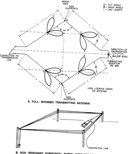
Rhombic antennas can be characterized as high-power, low-angle, high-gain, horizontally-polarized, highly-directive, broadband antennas of simple, inexpensive construction. The rhombic antenna (fig. 2-21) is a system of long-wire radiators that depends on radiated wave interaction for its gain and directivity. A properly designed rhombic antenna presents to the transmission line an input impedance insensitive to frequency variations up to 5:1. It maintains a power gain above 9 dB anywhere within a 2:1 frequency variation. At the design-center frequency, a gain of 17 dB is typical. The radiation pattern produced by the four radiating legs of a rhombic antenna is modified by reflections from the earth under, and immediately in front of, the antenna. B e c a u s e o f t h e i m p o r t a n c e o f t h e s e g r o u n d
Figure 2-20.—Conical monopole antenna.
reflections in the proper formation of the main lobe, the rhombic should be installed over reasonably smooth and level ground. The main disadvantage of the rhombic antenna is the requirement for a large land area, usually 5 to 15 acres.
QUADRANT ANTENNA
Figure 2-21.—Three-wire rhombic antenna.
element arrangement makes possible a radiation pat-tern resembling that of a vertically-polarized, omnidirectional antenna. Construction and installation of this antenna is complex because of the physical
relationships between the individual elements and the
Figure 2-22.—Quadrant antenna.
WHIP ANTENNAS
Hf whip antennas (fig. 2-23) are vertically-polarized omnidirectional monopoles that are used for short-range, ship-to-shore and transportable communi-cations systems. Whip antennas are made of tubular metal or fiberglass, and vary in length from 12 feet to 35 feet, with the latter being the most prevalent. Although whips are not considered as highly efficient antennas, their ease of installation and low cost provide a compromise for receiving and low-to-medium power transmitting installations.
The self-supporting feature of the whip makes it particularly useful where space is limited. Whips can be tilted, a design feature that makes them suited for use along the edges of aircraft carrier flight decks. Aboard submarines, they can be retracted into the sail structure.
Figure 2-23.—Whip antennas.
capabilities. Power ratings for most whips range from 1 to 5 kW PEP.
WIRE-ROPE FAN ANTENNAS
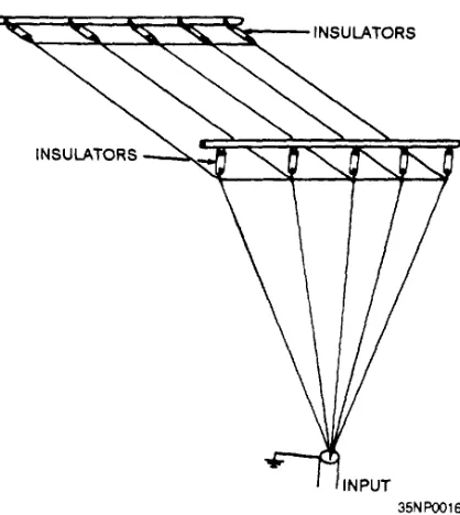
Figure 2-24 shows a five-wire vertical fan antenna. This is a broadband antenna composed of five wires,
Figure 2-24.—Vertical fan antenna.
each cut for one-quarter wavelength at the lowest frequency to be used. The wires are fanned 30 degrees between adjacent wires. The fan antenna provides satisfactory performance and is designed for use as a random shipboard antenna in the hf range (2-30 MHz).
DISCAGE ANTENNA
The discage antenna (fig. 2-25) is a broadband omnidirectional antenna. The diseage structure consists of two truncated wire rope cones attached base-to-base and supported by a central mast. The lower portion of the structure operates as a cage monopole for the 4- to 12-MHz frequency range. The upper portion operates as a discone radiator in the 10- to 30-MHz frequency range. Matching networks limit the vswr to not greater than 3:1 at each feed point. Vinyl-covered phosphor bronze wire rope is used for the wire portions. The support mast and other portions are aluminum.
VHF/UHF
[image:38.612.60.261.33.526.2].
Figure 2-25.—AS-2802/SCR discage antenna.
possible and away from any obstructions. The reason for the high installation is that vertical conductors, such as masts, rigging, and cables in the vicinity, cause unwanted directivity in the radiation pattern.
For best results in the vhf and uhf ranges, both transmitting and receiving antennas must have the same polarization. Vertically polarized antennas (primarily dipoles) are used for all ship-to-ship, ship-to-shore, and air-to-ground vhf and uhf communications.
The following paragraphs describe the most common uhf/vhf dipole antennas. All the examples are vertically-polarized, omnidirectional, broadband antennas.
Biconical Dipole
The biconical dipole antenna (fig. 2-26) is designed for use at a normal rf power rating of around 250 watts, with a vswr not greater than 2:1. All major components of the radiating and support structures are aluminum. The central feed section is protected and waterproofed by a laminated fiberglass cover.
[image:39.612.342.541.351.608.2]