KAYPRO TOCHNlCAL
MANuAL
3.0 3.1
3.2
3.3 3.43.5
3.6 3.7 5.0 5.1 5.26.0
6.1
6.2
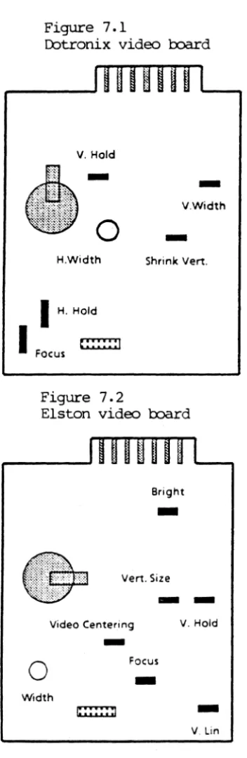
6.3 6.4 6.5 6.6 6.7 7.0 7.1 7.2 7.37.4
7.5 IntroductionPurpose of Technical Manual Soope of Technical Manual
FCC In:fbnra.tion M::rlel Speci fications
KAYPRO 2
KAYPRO 2/84
am
2X KAYPRO4
KAYPRO 4/84 . KAYPRO 4X
KAYPRO 10 KAYPRO ROOIE
RCM Revisions - CP/M Canpatibility Olassis
1-1
1-2
2-1
3-1 3-2 3-3 3-43-5
3--6 3-7 4-1Raicva1/Replacenent of H:lod (Exc. ROOIE) 5-1
'!buch-up In1bnnation 5-2
Mainboards-Troub1eshooting Tips
KAYPRO 2 (81-110-11)
KAYPRO 2/4 (81-240-n)
KAYPRO 10 (8l-180-n)
KAYPRO 2/84 and 2X (81-294-n) KAYPRO 4/84 (81-184)
KAYPRO Rc.EIE (81-296-n)
Renoval/Instal1ation Instructions CRr Assemblies
Descriptions and Adjustments Video Alignment
Video Signals en KAYPRO Mai.nboard
ALIGI.M1\C Diagnostic Listirg
Renoval/Installation Instructions
CQfl'fBl'S (ODtinued)
~Ql PAGE
8.0 Pc7Ner Supplies
8.1 Introduction 8-1
8.2 Description and 220V Configuration 8-2
8.3 Removal/Installation Instructions 8-5
9.0 Diskette Drives
9.1 Introduction/Disk Drive Cleaning 9-1
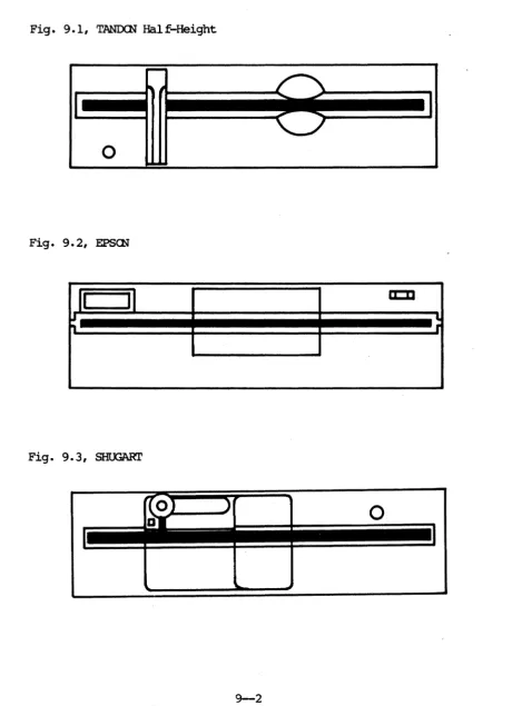
9.2 Which Brand of Drive Is It? 9-2
9.3 Jumpering Diagrams 9-5
9.4 High-Density (Drivetec) Drives 9-9
9.5 Removal/Installation Instructions 9-10
10.0 Hard Disk Drives (KAYPRO 10)
10.1 Introduction 10-1
10.2 Description 10-2
10.3 Hard Drive Con figuration 10-3
10.4 Hard Drive or Floppy Drive Removal/
Installation Instructions (KAYPRO 10) 10-4 11.0 Hard Drive Controller Board (KAYPRO 10)
11.1 Description 11-1
11.2 Removal/Installation Instructions 11-2
12.0 Inter face Board (KAYFRO 10'>
12.1 Description 12-1
12.2 Removal/Installation Instructions 12-2
13.0 Keytx::>ards 13-1
14.0 ROUE RaIoval/Installation Instructions
14.1 Cllassis Covers 14-1
CCJiI'lBll"S ( Qmt.inued)
SB!l'ICN PAGE
15.0 Troub1eshooti~
15.1 Introduction 15-1
15.2 KAYPRO 2 and 4 Symptan-Fix Guides 15-2
15.3 KAYPRO 10 Symptan--Fix Guide 15-8
15.4 RCBIE Symptan-Fix Guide 15-15
15.5 KAYPRO 2/84 and 2X Synptan--Fix Guide 15-21 15.6 KAYPRO 4/84 and 4X Symptan-Fix Guide 15-22
16.0 System I/O
16.1 Video Camland Protocol 16-1
16.2 Key1:x>ard Codes and Ftmctions 16-2
16.3 Connector Pin-o..tt.s 16-3
16.4
Port
Addresses 16-1017.0 Re ference Section
17.1 ASCII Chart 17-1
17.2 Merory Maps 17-2
17.3 Vendor Addresses 17-6
18.0 Suggested Re ferences 1S-:-1
1.1 PURJ?ajE CF T!XB1ICAL MN!U\L
'!his publication
is
int.eOOed to be a technical re ference guide to be used by trained repair technicians. It will attempt tocaver
all dealer-serviceable sections of Kaypro computers. '!his manual replaces previous manuals on thesubject.
The procedures and in:fbrmation contained in this manual assume technical
expertise on the part of the reader. 'lb avoid personal injury, do IDt perfbrm any servicing tmless you are a quali fled service technician.
It
is
our desire to provide dealers with the infbrmation and sUR?Qrt needed to expedite repairs and provide the users with the service they deserve. We encourage your conunents and suggestions regarding this manual.'!be in:fbrmation and procedures covered by this manual assume sane technical krlc:Jwledge on the part of the reader.
'!be J;X>licyof Kaypro Corporation is to repair computers to the modular level only. ENen Kaypro1s repair technicians do not repair switching power
supplies, CRl' assemblies, or disk drives. Repairs to Irodular oomponents not manufactured by Kaypro Corporation (J;X>Wer supplies, CRI' assemblies, disk drives) are
Nor
oovered by this manual.H:>wever, we do
not
discourage dealers and technicians who have the knowledge and the tools to repair to the compalerlt level :from doing so, on out-of-warranty Kaypro canput.ers.
'!be adjustment
am
rerroval/replacement in:fbrmation in this manual is organizedby module type, with the exception of reIOOVal/replacement infbrmatioo 1br the KAYPRO RCBIE, which is placed in a separate sectioo due to the di fferences in chassis design and hardware module placement in that machine.
As Kaypro keeps in step with oomputer technology, the models have changes which a ffect FCC ratings. 'nle proper rating is a ffixed to the back of each oomputer. Caltact the Kaypro Engineering Department if you need further in1brmation.
3.8 MCIEL SPl!ClFlCATICBS
3.1 I<AYPRO 2 SPl!ClFlCATI(H)
CPU
DISK srCEAGE
VIDEO SCREEN
I/O CCNNrel'ICNS
Z-S'" 2. 5 MHz
641< bytes
Sl-ll"'-n or Sl-240-n series.
Two 5-1/4 inch, double~ensity, single-sided, floppy disk drives, providing
19lK bytes of storage per diskette.
Detachable, 72 key typewriter style keyboard with IS programnable keys. Nal-glare, 9-inch, green tilOSPhor screen with a 25 rOil x S'" column
display.
Ole "Centronics"-type parallel port, ale RS-232C serial port.
3.2 IQ\YPRO 2/84 and 2X SP&!li'1CATIQ'IS
CPU
RAM
DISK s:raw;E
(Kaypro 2/84)
DISK srCRAGE
(Kaypro 2X)
VIDEO SCREEN
I/O Cc:NNECl'ICNS
ZOO-A 4.0 MHz
641< bytes
81-294-n series.
Two 5-1/4 inch double-density, s~le sided, flOJ;'PY disk drives, providing 1911< bytes of storage per diskette.
Two 5-1/4 inch density, double-sided, flOJ;'PY disk drives, providing
39m< bytes of storage per diskette.
Detachable, 72 key typewriter style keyboard with 18 programnable keys. Non-qlare, 9-inch, green phosphor
screen with a 25
row
x 8eJ column display.(he "Centronics"_type parallel part,
1:\\0 RS-232C serial parts.
3.3 KAYPlID 4 SPl!X!lFICATlQ'IS
CPU
DISK STCEAGE
KEYBmRD
VIDEO SCREEN
I/O CCNNECI'ICNS
Z-80 2.5 MHz
641< bytes
81-240-n series.
Two 5-1/4 inch density, double-sided, floppy disk drives, providing 39m< bytes of storage per diskette. Detachable, 72 key typewriter style keyboard with 18 programnable keys. Non-glare, 9-inch, green phosphor screen with a 25 row x 80 column display.
(he "Centronics"_type parallel port,
ale RS-232C serial port.
3.4 KAn'RO 4/84 SPB!IFICATIO!1S
CPU
DISK S'I'CiWE
VIDEO SCREEN
I/O CCNNEX:TICNS
MCDEM
REAL-TIME CLcx:::K
Z-80A 4.0 MHz
641< bytes
81-184-n
series.Two double-density, Cbuble-sidErl, floppy disk drives, providing 39m<
bytes of storage per diskette. Detachable, 72 key typewriter style keyboard with
18
prograntnable keys. Non-glare, 9-inch green phosphorscreen
witha 25
rowx
80column
display.
(he "Centronics"-type parallel port, t\\1O RS-232C serial ports, one RJllC ncdular telephone jack.
Built-in, 300-baoo ncdem, with Bell System
103
cacpatibility. UsesTexas
InstrumentsTMS99531/TMS99532.
Built-in real-time clock. Uses Natiooal
t+158167.
-_r."_
3.5 KAYPRO 4X SPB!ll'l~Q1S
CPU
DISK S'I'<::RAGE
VIDEO SCREEN
I/O CCNNECl'ICNS
MCDEM
REAL-TIME CLOCK
Z-80A 4.0
MHz
64K bytes
81-296-n series.
Two 5-1/4 inch, high-density, double-sided, flowy disk drives providing 2.6M bytes of storage per diskette. Detachable, 72 key typewriter style keyboard with 18 programnable keys. Non-glare, 9-inch, green PhoSFhor screen with a 25 row x 80 column display.
Qle "Centronics"-type parallel port, two RS-232C serial ports, one RJllC ncdular telephone jack.
Built-in, 300-baoo. ncdem, with Bell System 103 compatibility. Uses Texas
Instruments TMS99531/TMS99532.
Built-in real-time clock. Uses National Mo158167.
3.6 :KAYPRO 18 SPB!IFlCATIQ1S
CPU
DISK STORAGE
VIDEO SCREEN
I/O CCNNECl'ICNS
Z80A, 4.0 MHz
641< bytes
8l-l80-n series.
(be 5-1/4 inch dOuble-densi ty, double-sided, flowy disk drive providing 3901< bytes of storage per diskette. (be hard disk drive providing 10M bytes of storage.
Detachable, 72 key typewriter style keyboard with 18 programnable keys. Non-glare, 9-inch, green {ilosptlor screen
with a 25 reM x 80 column display.
(be "Centronics"-type parallel port, two RS-232C serial ports.
3.7 DnW) RmIE SPB!lFlCATIOE
CPU-DISK STCEAGE
VIDEO SCREEN
Ilo
CCNNECI'ICNSMCDEM
Z8M, 4.0 MHz
641< bytes
8l-296-n series.
Two 5-1/4 inch, high~ensity, double-sided, fJ..oppy disk drives providing 2.6M bytes of storage per diskette. Detachable, 72 key typewriter style keyboard with 18 pr03Iallluable keys.
Non~lare, 9-inch, green PhOsphor
screen
with
a 25 rOIl x 00 collllm display.Ol.e 1.'Centronics"type parallel port, two RS232C serial ports, ooe RJlle roodular telephone jack.
Built-in, 3000-balXl modem, with Bell System 103 compatibility. Uses Texas
Instruments 'IMS99531/'IMS99532. . Built-in real-time clock. Uses National ~8l67.
CP/M VERSICB I<AYPRO PARI' t ReM VERSIQT (:fDr CP/M disk)
2/83 2.2F 0777 81-149-C
or
81-232-A4/83 2.2F 1475 81-232-A
4/83
+
88 2.2F 1475 81-232-A2/84 2.2G 2619 81-292-A
4/84 2.2G 2622 81-292-A
4/84
+
88 2.2G 2622 81-292-A2 X 2.2G 2470 81-292-A
4X
2.2G 2340 81-326-ERCBIE 2.2G 2340 81-326-E
5.8 cassIS
5.1
amssm
IUD lBD1AL (FJCa:P1' I<AYPRO Ra3IE)1. Turn off the machine.
2. Disconnect AC power by unplugging the power oord :from wall outlet. 3. Remove the ten screws :from the chassis hood: there are two on top
and :fOur on each side.
4. RsIove the hood :fran the chassis.
1. IDwer the hood onto the unit.
2. Align the two holes on top of the hood with those on top of the chassis.
3. Insert the two flat-head screws into the holes on the top of the
chassis and start them, but do IDt tighten them yet.
4. Insert the eight round-head screws, :fOur on each side,
and
startthem.
5. Tighten each screw securely.
Kaypro Corp:>ratioo has small amounts of touch-up paint fur Kaypro hoods and chassis available to the dealers. Contact the Hardware Technical Sugx>rt personnel to obtain this paint.
O:::casionally a customer's computer will have scratches on the hood or chassis. A small amount of rubbing compound, when carefully applied, will often smooth
out very small scratches on a hood or chassis. Should painting be necessary, there are two sizes of sable paintbrushes to have CD hand: size 00 and size 000. 'Ihese brushes are available at any art supply store.
6.0~
'!he :fOllowing sections contain schematics, chip layout diagrams, and IC lists
(by U-number) :fOr Kaypro mainboards. 'nUs is not intended to be a theory of operation, but rather an aid to locating possible problems on a mainboard. Consult an appropriate databook (TrL, Zilog, etc.) i f you need to find out the internal \t.Orkings of a particular IC.
MAINBCNID TRClJBLESHoorING TIPS:
A blank EPRCM
can
be used to help troubleshoot Kaypro mainboards 0 f series81-1112J, 81-240, and 81-100. '!he appropriate roodel of EPRCM (2732, 2716, etc)
allows a quick check of the board. It will usually :fOrce the data and address lines to toggle" at approximately the same amplitude, allowin;;J the technician to use a scope to spot affected lines.
I f the video display does not show a screen filled with alternatin;;J "g"ls and apostroJ;:hes, you have a problem in the video RAM or associated
circuitry.
You
can
check the main RAM and associated circuitry quickly with a scope bylookin;;J at pin 14 on each of the RAM chips. There should be a pattern of signals like this:
For the 81-240 board: U212J (D7)
U21 (nG) U22 (Ds) U23 (D4) U24 (D3) U2s (D2) U26 (Dl)
U27 (00)
lC711
lC711
toggle toggle toggle
lC711
lC711
toggle
'!he U-mnnbers of the main RAM chips will vary dependin;;J on which mainboard you have, but the pattern will be the same.
~
1
S
-1 21.
J1c=J
1 UB :)
9)
7J"'~--UI) 1
:/1
ylr@l:((_---.,
9~_44
__
...,
UI ) I u. c.) _ _ _ _
UII)
1
ellV.~(}
1m ) 1
IM1 ,,) _ _ _ _
I. ---16
1 ---11
I
I
I I
L_-1
-c:=r.. ______
u
-
1---"
-c::J-~)c..--.-
••Ill" .. ·...
-='"
-
'-c::>
m~::.
. 2
1 I
U4
., y.
S
OND.
+.,
Y J-12 Y 2
+
"
"')----c;.t==JgCII
-c::J-.15
9-
\152), _ _ _ _ _ ... ; ;C~I
;
C/.
c - - - - tI
I I ..)
1-
. W "
I
'~
n . ' ...
un c.)____
L---~L___________ U~
fL __________ ...
ln.' ___
I_J."JS
u.
U . . ,,) _ _ _ _
1144"') _ _ _ _
U',,) _ _ _ ...
U6 )c.. _ _ _
'~_----,I
u •
00
•• . . . . RIO
c::::>
CIS'")
,,--_
..
c::::>
CI7
r---...,
UIO) "' _ _ _ ..no )"'-_ _ _ ..
,4
I~
U'.
I 10 )un)c.. _ _ _ .. UD
UM)"' _ _ _ _ 1.0
c..> _ _ _ _
IO
cSI . , )-U21 .
-UM
CSI
Ull c..) _ _ _ _ 1
0-
c..) _ _ _ Ul2"') _ _ _ _US7)c.. _ _ _ _ U7Sc..) _ _ _ _
UI5 ,,) _ _ _ _
lIB .... )
----'1-.... ) ---,
C7S
?J
U.'
>r---,O,,) ____ _
UII ,,) _ _ _ _
UII",) _ _ _ ..
UN) ,, _ _ _ ...
J.
a2
Ul4)
UP )
CC?!r----c::J---,
roo,,: ..
I
I
a:o · .
n
i
UlS -) ----,1
n
u.r-)--"1
-!
t~~1
1
_____ ---"
L - - - -
U
-IS
anQ20(1;
( / ) !)
-U
•• )
I)
u".-.----
-c::J--r:::J
U26 ... ) _ _ _ _
Ul7 "') _ _ _ _ 1
n
1162
E
IM+ ,,) _ _ _ _ _-c::J-R"
unUJ+ "') _ _ _ ..
"'1
o:Il~,'_U._7~_~~
____
I
c..) _ _ _ _Ie LISr, IQ\YPR) 2 (81-lUJ-n) Reference Designation U1 U2,U67* U3 U4 U6, U11 U9,
uoo
U10, U61 U12, U14, U32 U15, U39U16 throU;h U19 U20 through U27 U28 through U31 U33, U34
U35, U38 U36
U37, U56, U85 U41
U42 U43
U44, U45, U64, U65 U47
U48, U73 U49, U52, U62 U54, U72 U57, U58, U60 U59 U63 U66 U68 U69 U70
un
U78 U81 U82 U84 U86 U87 U88 74LS161 74InJ04 74LS290 74LS10 74LS393 74IS08 73IS32 741S74 74ISOO 74IS157 r-m6665 2114 74157 8216 74IS20 74IS02 745151 74IS174 81-146 74IS243 81-149 74IS04 74IS241zoo
PIO 74LS138 74IS373zoo
CPU74164 1488 1489
zoo
SIO 74504 8116 7406 FD1793 74IS195 74IS293 74IS390 FOC9216 Description4-bit counter
Hex inverter, CM:>S decade counter Tri NAND gates l)Jal binary counter
Quad AND gates
Quad OR Gates Dual "0" flip-flop Quad NAND Gates Quad 2/1 ~
( or equivalent) 64K x 1 RAM
lKx4RAM
Quad 2/1 MUX
Quad Bi-directional MUX
l)Ja1 NAND gates
Quad NOR gates
8/1 MUX
Hex "0" flip-flop
Character generator EPRCM
Quad bus trans
Boot EPRCM Hex inverter
Octal buffer
3/8 MUX
Octal "0" latch 8-bit shift register Quad line driver (our)
Quad SCHMIT!' line receiver (IN)
Hex inverter
l)Ja1 progranmab1e baud rate generator
Hex inverter, open collector Floppy disk controller
4-bit shift register 4-bit binary counter Dual decade counter
D3.ta separator
*NOrE: THERE ARE SOME VERSIONS OF THE 81-110 OOARD ON WHICll U2 AND U67 ARE WI' CMOO IC.S Bur ARE OORMAL TI'L ICS. READ THE NUMBER ON THE IC TO
BE SURE.
fn)(IE SIQ1ALS
ro
AID IN TlURifSIIOrDG (81-llB-n)The examples of correct signals shown below do oot represent all of the signals on a Kaypro mainboard, since most signals will be simple high-low toggles. A group of video signals (CCf2J through CC3) are includErl as
illustrations of the timing relationships between the various video signals. Note that only one of the I/O signals on U57 will be low at any given time. State of the machine: The door of drive A is open: the machine is waiting to
boot.
The signal measurements were made using a Tektronix oscilloscope, model 2213. It has a bandwidth of r.c-6f2J MHz, sensitivity of 2mV/em, a sweep delay of f2J.l microseconds to 1 second, and a graticule display measuring 8 x lf2J em.
Signal Ml from pin 27 of the
cru
(U63)was
triggerEd on. This signal is shownin the top half of each display and was channell. Ground for the signals shown on channel 2 was established at first graticule line above the bottom of the display.
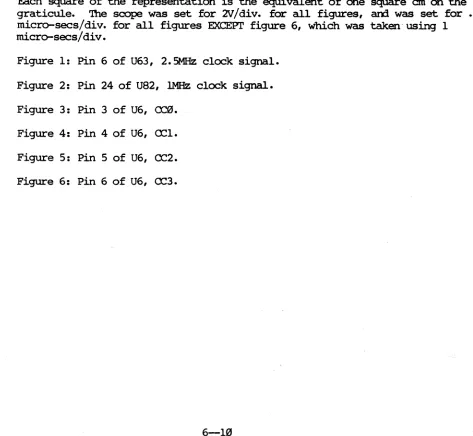
Each square of the representation is the equivalent of one square em on the graticule. The scope was set for 'N/div. for all figures,
am.
was
set for .5 micro-sees/dive for all figures EXCEPl' figure 6, which was taken using 1micro-sees/dive
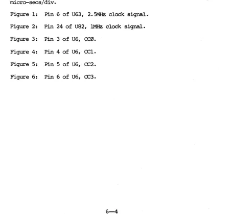
-Figure 1: Pin 6 of U63, 2.5MHz clock signal. Figure 2: Pin 24 of UB2, !MHz clock signal.
Figure 3: Pin 3 of U6, CCf2J. Figure 4: Pin 4 of U6, CCl. Figure 5: Pin 5 of U6, CC2.
Figure 6: Pin 6 of U6, CC3.
[image:21.617.69.531.336.756.2]FIGURE 1
FIGURE 2
..
~ ~-
..
~ ~,.
...
,.
..
,.
~ ~,
,
I
.J
~
..
- I '
t.~ , - .-III III ~ ~
•
•
III ~,. ,.
[
,...
~,...
,.
r,
...
'-I
.-
III. '-~FIGURE 3
FIGURE 4
I ....
--
~•
,.W4.
....
,.
~ J~,.
.,
J
I
II
,
L
J
\
-
..
~-
-
-
~-
~ ' - "---
-
-
-
-I .... ~
..
-
~...
FIGURE 5
FIGURE 6
"""'I
r
~~--
,
~ ,~ fill,.
~,.
fill,
...
..
u-
-
1
J
-
J
J
,
-
-
-
-..
~ [image:22.612.108.520.94.652.2]SIQ1M, I,.al\TIQ1S Q1 MIW1B(JUI) 81-118-0
Ie
SIGllAL . LO:'A'l'iCN PIN NO.
-CI?U SIQ1AIS
2.5
MHz
U 63 6·MREXJB U 62 16
ROB U 62 5
WRB U 62 14
MlHm' SIQ1AIS
RAS ·· .. U39· 11
~
U66
5MUXC U66 4
VIDBO CUXI( SI<J!IMS
CLCCK, Y1 U 2 8
CC0 U6 3
CC1 U6 4
CC2 U6 5
D C 0\
I
0\ I-' '11"t70K .\j,~
- --I Ll
1--Y2 ZOMNI
CO
I
)Drl1~H((M
('\ M'fQ~
(A)
=
, I11WlY
l:~ INO 1 Nt
... UD
=,-__ ..
147
UFRIO 'OK
'MHi i')
u<.3
~B80 iSO CPU
2~ luSto.
(8) iiif - - - * - - + - " ' - 1 I N T
(8) D,a
lB)INnn 11 NMI
•
I
AlB...
...
Ito)
l
A78IiWOJi
M1Y
., 1"'~7. ---...!LJ
Ab 3"
AS 35
. . ~,3!!' _ _ _ -'4
A! I - l l - - - - " l
AlI~---~
.. I"'LL' --r--llJ •• p3!lL.._I---"I
D?
DID
!Q-O~
~~_4_+-.f_.._I---+_~
D) I"'c--+-HH~ 02 IL_
O. ~''-+-J.-t-++
o. , ..
r--""UiVf'l{\J"",. O Q O C l a O C Q
L---$'_'.-...J
II'H)
1
1""7)
11'8'8)
(PC r) (B)
(""'·11)
I
(",,·w)
J
U47 Z1lb A14@. ABB AI2S AII~ A10~ HB
:~: (A,B)
•••
ASB
...
A'.
AZB "
.
...
M'I
D •• 05. 0<1 (A,c) DZ. OIB." j
- - ole
-+--... +---
",iE,'.
IA,t)~----I---- ~ (A,B,t)
--- wn (A,B,c)
.- . - - - UiNl\ (A,B,t)
~---~
, - - - I . I D ?
. - - - ' R S T
14'S<1O
.IL pNle
_ _ _ -'oj, ~ ./t
7-'4l51l8 . ]
---1 '" • IS
" \I 12
2
.(VISIONS
ION[ LTII. UfECT. Olsallll'TlOlf DAn ~o
& RfIlftlMol; ... !I SII. UrI( i-c' ~'Ir) -5,-U
- - - 'U51 PIN~-WA'i.!i'irt. .U1,'!o~Til 1-}lS WU( RE.W:ncO. 06.1 I Do,. U&i[.L S
rw tJi~ VCRC rCU~D
81- 111
SHUT 2A
D
c
"
(A)
I
01 14 07 D~ 13 o. 05 12 D!. D4 11 0<11 ()3 \0 D!o
DZ 'I Dl
"'
--""De 7 [).
AI -.~ AI
AI 5 All
I MHi'. l4 tlK
7 6
D' 010 os 0< OJ or DI : lIe (71 J6 ~ ODD NOS
--~I
IA) DO
, TO GNO
..J, __ ~ ____ -,
TI I>"'----"~~----':c_+_+_+___+___+__+_: J' -8 iN6l"X I
'fiii :Jf,-2" T~K" :
'J"-ZQ WIT PIt:OT.1
, I
DOat I"'---'~)O:!'----+---+ I J"-18 SlEPTN I ,il)cJC----'-""'=-~+--+_ :J'--Z1 ~ITt :
f">---'---'.,,~!>O,'---'___+-: Ji> -eo SfEf :
LATE
US2 1793/7 DISK
HlT 23
I _Ie
I
I'-<--dIoiNl~ , l ________ J'-22 Wrf""iim:
j
DISK DRIVE'
"
t
031 2004
- ~ R~W -OAH ~
R35 ~ _ J'~~_ J nlA
(s) p",,,
1Nf %PiO
,.
..
mR lilfiiB" MB.. 8
1
I') 07
l
IlIo05 DO 0] b2 Df D.
(i) rrl1.
un 3881 S'f':iPIO -0[" R'9 4
1-) IWJDB (I'<) IWJD'
r
(,)
l
smK (')
rJ~_~.-~~
'- - - -I I , -!BJIIU!.' ,
I"'----llf~>~c:__ .... : Jt -, 5T'lOeE:
'*""==---; J2 -11 KU')Y ,
I
I
1U---<>f10
~"'"'=c_:_--:J'-12 mvn I
I"----'-juil)o:"'----I J'-ID DRIVE ....
2
.[VIIIO"S
lOftl L11t. UrEa. OUCII ...
....
...
•
Ifrw_; wu. ~II I t t l f h-5.l1'f") -.0' ~w'un ... " IIfIO ItO a.L(. 1'X) . . ],'5 "J
-, mm. "IItU UlD .ro CIt .!I, J'
0 u1 ... , ~ UIU[I) r.; .... 11, ~. ,
..
D
MCt1A9 WI4M
~'I'e~~c
+
~ ell ",70,., :- I C13 170 PF+
-SCItIM r/o
:- J-4- -i
'-I ('M C.ND I
, I
: -7 SI(;, GND,
,
-,
T.O ell :
1.rr
'-] r.D ,
'"
,470 Pf I
,-" m c •
,
..-' , -s
e"lS , ,
n" I C
"'iliff, D7
...
:-i>"""
"" 3 .. DCD
DS
'"
D1
"
..
03
..
D2 III
t
r---,r J)-' I
Of
..
I Jl-" 18[[J>
i ' , JJ·Z ,II&D ' I.B-~II"
I
L __ J- f
K£lr.oMW""" (0)
•
NON-UNEAR SYSTEMS. INC.DB.. ... ~ . . .
..
...
.
,""'" 110 AltD DISK CONTROLLEIC'
"
7~H(D"
-.!.~Nt '..;.
YI H ~11" ~1Ii!
V
NIt
---101--'-D 7"'1HCDof
~'~~L . . . ~
Rl .2
(1 +'111' 17!lK Cl
30PfJ 150 PF
704lS0l
10 11 12
"
C
,.
15
7~l5138
0'1
I
'") "o80'1 (e) ee. (A) 1.18
W Ic) CCI
(A) A2.
(C) CO2
(A) A38
Ie) eel
fA.) A4B
(c) Cl<
(A) AS8 (C) CCS
IAJ A • •
Ie) cc.
IA)
.7.
(e) LC.
IAJ AS. Ie) LC'
IA) A'S
1<1 LC2
I. AIDB (e) LCl
If.) AllS
(c) LC+
II.
6
9 '71 L'5 10
Iik~NIe. ~
\Sl ... c-.[flvlll'41
... t.,..l..Jvw ...
... vl..Ju .... u{J
~S----l
u,.
Zlf1
II/C~' 2 u15 _Ie. ':' 74l'EollO
u,.
t'14
l4 1 Il 11
aJ. Dl 01 0.
U31
2114
Ie) CC. - - - ' 4 - "
Ic) C C 4 ----'..-~ (e) CC 5 -~""--"
7.t1LS3Z ~ .~"Nle. (ClOCB r (c) L 7"515\
lONl LT •. UFtCT.
•
(1
."
E2
VIDEO
r.:f)' :
I I HORli. 5YNC I _ _ _ _ _ _ _ J
',WPR,r c,~';y
If\jr:~n .. '·:1
..
",~ I .:
-j"-(Cl' ·:.I~ "i' .
.~~ jl';:'"
• -'~I'!<:
';,,;-1.
D
c
~
~.~'
. ...
~911.
• NON-UNEAR SYSTEMS, INC.DlMlHSIONS AlII IN INCHU DB. ... (:AUII"OItNIA TOLEIWilCES ON DMWJrt
~=-' ~:: CItlOt CRT CONTRDL
~ ItEL[AS£o..n
..
"""111-111
CPU VIDEO 1/0
RAM Address Display Character Video
I
ClocksI
Multiplexing Blanking Generator Driver Fioppy
Disc C
0
RAM N
Z-80 Video Video T
CPU Addressing RAM R
0
L
Data Bus
Buffer Video System
Parallel
Clocks
Ports Monitor
ROM Serial
Data Ports
Control
I
ResetI
Data Data
I
I
Port
Keyboard Selection
Memory Address Address
Management
Control Control
, • J .
1Ic=:J
tU;+::::::l,
In I.> _ _ _ _
y
~9)
.. -..
c.g1)"
ItiffS:
Ic;:>
~_
.. ___
.,-VI
>
Iv.
tL) _ _ _ _u.>
V" )c:::>
CII~-)---"o
U.
II2f l.' _ _ _ _ I _J2
,.---
-===:~:1---q
Ml L
, _ _ _ _ •
.. 2 I 4 S I .
->
'---~
.1)
~ a~
E~
-=-.•
'M.. )
I
gL ____
1
U7,---1:':"'---1
~L
_ _
__
I ••
I
C~
V~
f
US2l.) _ _ _ _ _
vn I.) _ _ --.Jl
u..L) _ _ --.Jl
u.>
., .S .7"
(}cto
0:0:0);(1
VQ ). . . a20
~
00
C7aa4 . . . 10
V20 )
V2' )
vn )
~
V56 )".
C • •
~
()
U57) )
VII
10
CS',
L _ _ _ _' - - - - V34
V22 )
-
...
)~
c:::>
uti) til'
~
UIO
~S
NO
1 >
1159)cn
()
v •• ) ~ ~----.,1
VIS L) _ _ _ _-
.12 U42u t q
UII )
-.:to
~
utS)
~
UII
~c:::>
UH)
c.
N
ut7 ) • - )
I.D
fro-:"!
I
V.3f
()
vu
>
I~...
~'~'
7A=
1
n
-)1...::::::::!1
~ ~L_
-L-_ _ --.Jl VIt
~
1 . )-V37 ,> _ _ --'
va. ,) _ _ _
-c::J-a ..
n
I
I I
I I
L_.J
I
..I
-c:::r..- _____
2:.
42I •
1129 • _ _ _ _ _ _
at
CIJ~C14
.s v,s
..c:::::>
"
OIlD 4'
...
~.
_ltV JCIIC:::>
IS
·'2 V 2
C 8 ,
.,
C.. ..
124 S 126
n.
I
12, u, V7I )I
na
140
J4
V75
>
I~
V7. vn,~)
•
• 0 ) va. vaon. an _
JS
J.
1000
a
~i
- 20
VIS J7
>
I>
-Va.
...
~-c:::r
-I>
c=J
va7 un
n
29
••
•
Ie LIS'l', IQ\YPK) 2/4 (81-248-0) Reference Designation Description
---,---
,---Ul U2,U67 U3 U4 U6,U11 U9, UOO UUJ, U6l U12, U14, U32 U15, U39U16 through U19
U20 through U27
U28 through U3l
U33, U34 U35, U38 U36
U37, U56, U85 U4l
U42 U43
U44, U45, U64, U65 U47
U48, U73 U49, U52, U62 U54, U72 U57, U58, U60 U59 U63 U66 U68 U69 U70
un
U78 U8l U82 U84U86
U87 U88 74LS16l 74HCU04 74LS290 74LS10 74IS393 74LS08 73LS32 74LS74 74LSOO 74LS157 MCl16665 2114 74157 8216 74I.S20 74LS02 748151 74LS174 8l-l46-n 74LS243 8l-232-n 74LS04 74LS241zoo
PIO 74LS138 74LS373 Z80 CPU74164 OCl488 MC1489
zoo
SIO 74804 8116 7406 1793 74I.S195 74I.S293 74LS390 FTC9216 6-9 4-bit counter Hex inverter, <NOS Decade counter Tri NAND gatesDual binary counter
Quad AND gates Quad
OR
Gates Dual "D" flip-flopQuad NAND Gates
Quad 2/1 MUX
(or equivalent) 64K x 1 RI\M lKx4RAM
Quad 2/1 KJX
Quad Bi-directional MUX
Dual NAND gates
Quad
IDR
gates 8/1 MUXHex "D" flip-flop
Character generator EPR<M Quad bus trans
Boot EPRCM
Hex inverter Octal buffer 3/8 KJX
Octal "D" latch 8-bit shift register Quad line driver (0Ul')
Quad SCHMIT!' line receiver (IN)
Hex inverter
Dual progranmable
baw.
rategenerator
Hex inverter, open collector Floppy disk controller
4-bit shift register 4-bit binary counter
Dual decade counter
The examples of oorrect signals shown below do oot represent all of the
signals on a Kaypro mairtx:>ar:d, since most signals will be simple high-low toggles. A group of vide::> signals (a:0 through CC3) are included as
illustrations of the timing relationships between the various vide::> signals.
tete
that only ~ of the I/O signals on US7 will be low at arr.t given time.State of the machine: with a blank, 2732, EPROM inserted in place of IX>rmal
EPROM at location U 47. The door of dr~ve A is open: the machine is waiting to boot.
The signal measurements were· made using a Tektronix oscillosoope, model 2213. It has a bandwidth of OC-6f2J MHz, sensitivity of 2mV/em, a sweep delay of f2J.I microseconds to 1 secald, and a graticule display measuring 8 x lf2J em.
Signal Ml from pin 27 of the CPU (U63) was triggered on. This signal is shown in the top half of each display and was channell. Ground for the signals shown on channel 2 was established at first graticule line above the bottan of the display.
Each square of the representation is the equivalent of one square em on the graticule. '!he soope was set for 'lV/dive for all figures, and was set for .5 micro-seeS/dive for all figures EX.CEPl' figure 6, which was taken- using 1 micrcrsecs/div.
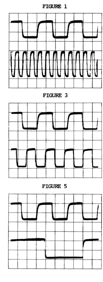
Figure 1: Pin 6 of U63, 2.SMHz clock signal.
Figure 2: Pin 24 of U82, !MHz clock signal. Figure 3: Pin 3 of U6, CCf2J.
Figure 4: Pin 4 of U6, 0:1. Figure 5: Pin 5 of U6, CC2. Figure 6: Pin 6 of U6, CC3.
[image:30.612.65.538.324.760.2]FIGURE 1
FIGURE 2
--
-
'-
.-I-r
{
I
-
JIll!r
~-,
~I
,
J~
U
-
~ ~,..j
"-
Io.ot,
"
lfliir ..
p p , lflii-, ~
,...,
,...,
II'I
\I \0
"
\.
"
"
\0U
...
...
'--
'--
"-FIGURE 3
FIGURE 4
-
~Ir
1"'""1r
~I
I
J
U
-
-
-
"'"
~-
l1li,.
~,.
1--'1f
J
L-
-
,...
-
P"'"~
...
...
~-FIGURE 5
FIGURE 6
-r
r
I
•
-
,.
III,.
,.,
,
J
~
-
r--,...
!II' ~....
...
...
.. Ij...
..
-
I [image:31.615.100.519.100.729.2] [image:31.615.105.304.104.649.2] [image:31.615.332.519.111.689.2]SI<J!1AL r.crATIQiIS, 81-248-0
IC
SIGNAL
~TICN PIN NO.-CPU SICHUS
CPU clock
U 67
6
1
MHzU 87
13
2
MHzU 87
3
MROOB
U 62
16
RDB
U 62
5M1R (re ference)
MEM<m' SICHUS
BAS
U 39
11CAS
U 66
5MUXC
U 66
4VIIEO
a:.ax
SIQV\ISCLCCK, Y1
U 2
8
CC0
U6
3
CC1
U 6
4CC2
U6
5CC3
U 6
6
(A' Mfm"---..J ,._"_L5,02
2 U5~
J1-1 2 71L501
JIIf 0--"Ie
PRQPRIETA8.Y
INFORMAllA
tfot'QI tltslnbulfOft
U,. ffSfT
3 7~l502
2 U37 ),!-1 _ _ _ _ ---'9'-'""-l-..,"32 <""" ~
~...!2 iiMi \!, HMT ~ IL-_ _ _ l--_ _ --.l
L__ _ _
t'
I
7"l~B
•
pOle
MATtlllAl_,,1110.,
ZC»C L UfICI'.
-
..
-•
~;_Sl.UUC: h-_I)....
....
u.n PlIII 1 . . !nIl..LIH PIlI! tOtu ~..
""., .'.«va. 010. ,D7I LAUU .~.
tW, ~ we.. UlUVo.
IMM1." 'CIIIIIlTlD lD"'S ....
-.
.~.7<1lS15.1 f2 9 -4 ., 1 0'" a2 tl\ 1»:
I
1~ U31
1""" ~ .. M " ' . .
"I "I "I "I '1 z 1"1 '1
~::U;~~~~~~ . - ; < < I I { < < C C 4 :
~----'---- ~
HOMEMCLATua[ OIl
OfSCItII'TKIff '''ITS LIST
I=ICI~ITI~"
NON-UNEAR SYSTEMS. INC.
KAYPf:O Jr/4
81-241
SH[[T 2A
WK
RDB
wsm
""-=
--,
: I. (7) J6 -¥fiDrJ:iS
.J r - - - ,
1i!'4li~"I'-1-t-j-lf--f--t-+-; ,,-B ~ 1
P-',+--J,i~fD-4-l-lf-I-I-t_ : J' -Z. UK ~I : ~~I<iia!UL:~~-If--f--t-t-'JO.-2 Q wrr PkOT.' f"'-+-":';"'I»'L.~>-I-t-t_ : J'~'8 ~ I
ilxJ-:-2~=-""+-+ :J&.-Z1 WRITt
P"+-'----'a;.i!><>"----~t_ ; J' -ZO SflI'
DISK DRIVE'
01 [Jj, 05 Il4 03 or 01
lAl'J
Ml11 Pm'Ili~19 R'1?
(A) IWJOQ
(A) BAllO.
r
07[Jj,
D5
(A) Of
l
03 02 01III
_(WiltON,
''IN, Ullt. unCI, DOC ... DAn
-•
Rl'M"' • ..s SM tDIII" IT." SoliU") -s·u "~TUI~ '*4 IW) tID Lf. UlO'lII U ·l·" .~
.
... ~ mm. AD'ED CltD .ro '* JI: .. ,
LAICL'S OM PI .. !>. n CfVl~OI!A
,.
'~T" ... ., r. K .... '
Melta' MC.I_
SUII'l I/O
.---
-,I J~ I
~"'c ~N/C
+
~ CI7 170rF :' I CI3 110 PF+
•
1-1 tH 'ND I-:-7 Sf' 'NO'
• ,f
3 ..
---~_+~+-~_+--~~e
U70
3881 SIO
, ,
T'''I-'''-~9~--t---I-Z T.D 1
ell :
'fL_~1-11O ___ ", -] r.D ,
(I, 1
470PFI
tru~>I>"'t-~t--t-, -~ no;
CI. I
If:
'1'-"---+ ___ ,-5 CTSeM ,
4'Mft'1
~-"vv--t--:-" IS
DCD
.3.
200 ..
f-L-+--:"~
Ii:
~n ~10K 12K
1---;;:;-l1+~=L-=-+-£ANI( (A) J3SL _ _ -_ _ _ J
300 ... 1iIf MPiD MIl ~ lIim AlB AlB 1
PROPRIETARY (A) D7
INFORMATION
l
""
05Il4
fI1!t lor dlOtnbll4 ... Dl
02 OIb ...
01
aft, ather Dtt_
01
OfpAlllllOftOf
<_wdllout
(0) rrn
lht pernliSIMIR
_.Cor"",,,, ...
ofrJ~_~'-~~
1 - - - 1 I --lI!I.8l£!. '
, I
I"'--..-.,..-"-l~~:;;_~: Jt -1 S1'1ll!E:
'IF---~J~ ~~Y_ ~
JL>----'-jo.oj>,.<.---:J'"-32 SS£L : . ..:11£: 9!J£t -09 51[)£ 1 5Sft. • 1 0 SIO£ 0
kr~U~"'-;;=;..----:J'-12 iiliVn
'!><>"----: J'-10 D~lvtA ,
L _______ ...J
...
-.., . ; ; . . • • • ~MTt
...
~n (8\
,AUI LIlT
•
NOHoU _ _ INC.(') '08
(I:) CC. (A) AI8 (e) eCI
(A) A2a
(e) eez
CA) A3B lc) CC3
(.1 ...
(c) Cl1 CA) A58
(C) CC5
(A) A.e (e) (Ch (A) A7e
(e) le 0
(.) AB!
(e) lCl
IA) A9B (e) le2
(A) AIDB
(t) LO
(A) AilS
Ie) Le4 ~"NIC ~
I ?1L~14
Nle
·
NieU3l
Nle 3 ,
•
•
N/c•
0
r::::.
I :: l:s~t'=A'PUCATKIft art.
UMl.USOntlllWIKSI1:CIIIU) ~TR.
DlMENSIONS.utE tN INCHES
ZON( LTa. UfICI'. e
I I ,
+£1
I'W" 0 ••
-
Oil p ......
.~,.---.----J
PROPRIETARY
I NFOft:".~I10"
NJL -0 £3 K[l
I\(it Irjj ~r;trlblltIQj.
'-: tIiI"'-'\!"'Jf: :0
j:l, n~~:" ·.··· ... 'r
Ni~fI,: ... ! 0'
tl"!,r,lolll 1:II'Iul t'lo!l)e.m,')")'I(I,ll)j
• ~i!K.;'.1 ;rJr~'" Jt!:,.,
'--- ...
_--_.-NOMENClATURE 011:
DESCRIPTiON PARTS LIST
NON-UNEAR SYSTEMS. INC.
en (ONTROL
KAYPKO JL/4
UI
CI ~L _ _ _
c::>
U2O
f _
U8 JI
~--UI4o f
U21f
C22 UH
c::>f
U2S
f
C32 UlO
C::>f
Ull
Ul4
c::>
C42
DOl
J2 J5 JJUIS
. U22
L~ ----I:i~i§
U2l? _ _ _ _ _ _ _ _ _C2le::> U26
~==I
f
Ull
0
- - - ' 1
C34f
.
U27J6
RNI U6
~
usf
I
~4 L~
- - - - CI4 UI2C::::::>
l _ _ u_ll_ IORsUII I e : : >
L~
_ _ _ r- U20f
UI8 C21 UI9 1~
c::::>
l C76 _L _ _ _ ClO+5 J7 GIJ
ISPR +12
- - - -12
- - - - I
L( - - - .0
i
""
I
.~.
f ':',::-:
0
0-L_________
~
Ril -c::::J- f!.J+ J8__----.:::U2-=-.8 - - I
0
J
0 U29f l U
- ~ ~ ~ UJ2
It: 00 C l ( : : : )
= - - - - = = : ] 1
~-J91
Ul9 U40
f
I
~
Ul7
f
_ _ _ _ U..,l;cl---["
O _ C l l U _ l S 1
~
I
~~-U4~0
L----C38e::>I~
-- _ _ U_4S _ __,~
usa O .b~,~'
---I~
___ _
~
U4l
f
C41U49 e : : >
U44
<=2
e:,
~
- U - S 6 - Q;~O-=====
L _ _ _ _ _ uss
I
USI~
US4f
----I9L-L~
__ __
I
f
U60
}
U6S
~ U61
c::,
I
I~f
8
L~
_ _ _L _ _ _ _ [l
8
U66~
Sf'R CSSO _ _
---'I
~.
US7O
60
un~
U67
~
R 1 8 § C60
C61
!" ....
0--un U
U42
c:::;
~o
I
un
f
US]
eso
~
e : : >US9
f
~O
O U72 eS9
5
}
I
~ ~e::>
US8 It:
0
~O
---'U6300f
g U 6 4I
0
y] : :
§O---'
un C72 C
PC 81-18'
US2
Ie
LISl', 8l-l86-nReference
Designation Description
Ul 74874 Dual "0" flip- flop
U2 74808 Hex Schmitt Quad AND gate
U3 74804 Hex inverter
U4, U10 1489 Quad SQf.UTI' line receiver
US, U38, U41 74LS244 ectal buffer
U6, U2l, U24, U33, U49 74LS74 Dual "0" flip- flop
U20, U30 74LS08 Quad AND gate
U8, U37, US0 74I.SOO Quad NAND gate
U9, US9 74LS393 Dual binary counter
U11, Ul8, U3l, U4S, 74I.S373 O::tal "0' latch U46, U60
U12, Ul9 74LS138 3/8 MUX
Ul3 7406 Hex inverter, open collector
U14 74886 Hex Schmitt Quad XOR gate
UlS, U61 74820 Dual NAND gate
U16 8116 Dual progranmable baLD. rate
generator
U17 1488 Quad transmitter
U22 74LS16S 8bit shift. register
-U23, U27 ZOOA SIO
U25,
un
74LSl0 Tri NAND gateU26 81-187 Olaracter generator EPRCM (2732)
U28 Z80A CPU
U29 74LS195 4-bit shi ft. register
U32, U43 74LS02 Quad NOR gate
U34 74LS14 Hex Schmitt inverter
U35, U44 6116 AAM, 2K x 8-bit (200ns)
U36 6545A-l Video controller
U39, U54 74LS245 Bi-directional 8-bit buffer
U42 81-302-C I3oc'&t EPRCM (2732)
U40 74LS32 Quad OR gate
U47, U48 74I.S157 Quad 2/1 MUX
U51, U52, U57, U58, U62, 4565N-15 Dynamic AAM 64K x 1 (150ns)
U63, U68, U69 (t-bstek number)
U53 74LS163 Synchronous 4-bit binary counter
U55 14-2-392 14-Pin pull-up resistor
U56, U65 74LS04 Hex inverter
U64, U67 74HCU04 Hex inverter, Q.1CS
U66 74LS93 Asynchronous 4-bit binary counter
U73 WD9216 Data separator
U74 1793 Floppy disk controller
The examples of oorrect signals shown here do not represent all of the signals
00 the 8l-l8a-n main1::x:>ard, since most of the signals will be high-low toggles.
A group of signals taken from a video clock divider (U66) are shown to
illustrate the timing relatiooships between the various video signals.
The signal measurements were made using a Tektronix ocillosoope, model 2213. It has a bandwidth of OC~ MHz, sensitivity of 2mV/em, a sweep delay of g.l microseconds to 1 second, arxl a graticule display measuring 8 x 19 an.
Fach square of the representatioo is the equivalent of ale square em. 00 the graticule. The scope was set fur 2V/div. and .2micro-secs/div. fur all
figures except figure 2, which was set at • Smicro-secs/div.
Signal HI from pin 27 of the CPU (U28) was triggered 00. This signal is shown in the top hal f of each display arxl was channell. GrourXl fur signals shown
00 channel 2 was established at the first graticule line above the bottom of the display.
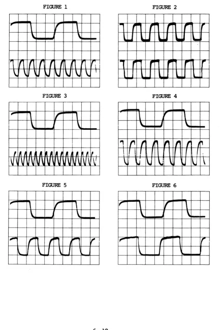
State of the machine: The machine has just booted-up on the hard drive. Figure 1: Pin 6 of U28, 4MHz clock signal:
Figure 2: Pin 24 of U74, !MHz clock signal. Figure 3: Pin 12 of U66, video, clock divider. Figure 4: Pin 9 of U66, video, clock divider. Figure 5: Pin 8 of U66, video, clock divider. FigllI'e 6: Pin 11 of U66, video, clock divider.
FIGURE 1
FIGURE 2
,
\
I(
I~rr-.
r
r
r-
r
\
\
\..1
"i.I
.. u
l1li
'-11
II
fl
Ii
,
I
11
1
1(\ I~ pl"""l,.-
,.
,...
,..
\
\~
J
~
V V
\J
\.
1l
"
L....
'-FIGURE 3
FIGURE 4
..,.
\.
J
\
"
"
f
~If
f I
J~
I
,
U
\J
\J
\
l\.
\
FIGURE 5
FIGURE 6
\"
,
r
\
I"
I('
\
\
\
\
\
"..,
r
n
f
,
J~
,-
,-
II
,
1
r
l
J
\.
1
\ 1
\.
J [image:39.613.87.528.81.729.2]CPU
Z-80 CPU
AAM Address Multiplexing
AAM
Data Bus Buffer
Monitor AOM
Memory
Control·
Address
Video Driver
Video Clocks
VIDEO
Character Generator
Video AAM
Data Control
CAT Controller
Management
.1---1
D.ata
KAYPRO 10 BLOCK DIAGRAM
Hard Drive
C
o
N
T
A
o
L
Parallel Ports
I/O
Floppy Disk
C
a
N T A
a
L
Serral Ports
Port
r:::::l
• f
Uti
i!'iOA
TID-"
.1JO-) P,.JA.,lf\I(b
.lID-I
s .. ~~soz 74lS3&
(D) DRQ :-- ~ ,
(D) IN1Mq --...::':.. L--rJIJ.~;:.~3 iV'{O,b=3+---:..;1-'i7 "1'\'
C.",D to'ALl "
at
sPAtE-n-1
-IZv J7-Z ~12v TI-!>
,.,.,0
J1·~j(1..., 11-5
+Sv TT-'
(e,~.[) IIST- .
-TO: Ut.I-I, S'Z-S
TO; UIoI-I'. 1'l.-Z, USS-~O
9
AJI<(;.
,~
~~
______ .________
l.~
NEXT fiNAL
A55Y. ASsY.
APPliCATION
NEXT ~INAL
ASsY. Assy.
QTY.
(AJ
A7---+
4
MATERIAL
REVISIONS
ZONE LTR. EFFECT. DESCRIPTION DATE APPROVED
I3A7
SA'
BAS
e.A"f
BA}
!SAl.. \lAI
B "'III
U.5£D:
f
PROPRIETARY
I
, INFORMATION
No: ,," :IIsl1lb11ll'l11 " blnsflllSSlOlllr.
... , ;;tlle! petSUl1
orpn,:,'.1or. /Jf rom,,"~, ,,"00',1
the ~'fml!.!·IOfI tit
-.J
lIa,..,o Cc:",1,amn
'---NOMENCLATURE OR
DESCRIPTION I MFR. ICIRCUITIIlEM CODE REF. I NO. PARTS LIST
NON-LINEAR SYSTEMS, INC.
SC./-JEMATIC; PR..OC~550R
KAYPRO 10
M
,·
"'f.. ··
'I,
.
4J' ,.,.,.,
l.),~n
""Y-
~-~
.,.
7~ ')~
~.--h~~ ~'"
7VL $00
.
" •
'--"
~~.
)JO ....'
AU'
"''::-
,'0 ....L::" u('" u
~, ,
...
,eL'
.,.
,.",.-,,",
..
11-) ",,0,.0
JI·~ ",&'(
.,.
"or
7<f","0"
.
,"n 7~
. , UI II
~
.,..,...
--
...
V IVOS. ~s(D:
£»of( AJI'IIMMD
..
-'_-4- __ ~_
, h i loT
PR()P.R'ET~V INF~~MATIOff 1Iot ... . .
or ... .
any 1I1IIr";" _
...--
...
= .
..,..,~Po c,.. 110<>: &,-180
.-~.
'AI" LIlT
~~INC.
,.
,
VOL ~ 10/1!>(M AIS' &
(~)A7~" U"I
(I'lMt-:-'--1I
"
I ~ 1I~/d(~) A' -_._" ~
'"
(Aj IIll : /I ;; ~ 7 _____ 1_° ",,/'1
(A) A>- '0'" ~ ! ___ 'i
Ai/liZ
(II) "'2----" II
(p..) ,..'1---A
"."
U':''I" f
1/<) MIIX
''ll<-RAM
1 If'
,
(A) All 13 ,.&
AI'
,uc '" Il AI/II(A)M
'0 U'll '!. ____ t. MilO
(I\) A 10 II ~
(AlAI
"-VI
7 AI/'I
(A)lIq
,
.
;0tAl,. I 'Z • ~
(A)Ar
'
.
~ 1(A)" s.
~)
CAl MRI4>·~D
7"4L.SO'"
(A) PROM Cf:
us. U~z.
BANK (D)
~ _ _ _ _ -.<~'1:L..._ AI5 (A)
7'1(30<1
74lS0"4
US!.
f,S
1ou~1o
J ..
1"t5~"'"
VSIo
NEXT
ASSY. FINAl ASSY.
APPLICATION
NEXT IHAL
SSY. SSY.
QTY.
I.J !i7
')1 i)O
REVISIONS
DESCRIPTION APPROVED
ADD Co,..,_. TO lICof,
II:~"'I lCD 3.,,.. .... NO", Ar
PART OR IDENTIFYING NO.
U A)OS t.J.H:t>:
rPRO'PRlHARY
I
I
iNf-'JRMATION
I
--.----
!
I
Nol II" r. 51 •• lr:tl(.r.Of tr''1WJ~l to
, 1'" ~:!'"' p..-r';,)n
I
tkJit/U~. :'''' .Ir
t l ~r.,lt"f .·':tn"f t
I
·t., ;"''''io~,' :,1 I~ __ ~~~~:~~~~ __ J
NOMENC~TURE OR
DESCRIPTION
ITEM NO. PARTS LIST
UNLESS OTH[RWIS[ SPECIFIED CONTI!.
e
NO. •
DIMENSIONS ARE IN INCHES DEL MAR. CALIFORNIA
TOLERANCES ON ED~R::A::W::-Nt--=-~_-t",'O,,-• .!C...,.!..'.:.ti-""'::::' _ _ _ _ _ _ _ _ _ _ _ _ _ _ _ _ -I
NON-LINEAR SYSTEMS, INC.
DE~'~~LS A:g.L~ pCA:!:Hpp~E!<RCK~ _ _ ~ _ _ --+----t
FRACTIONS • '-"/~
'" 1/l2 RELEASE DATE
SCHEMA,'C, RAM
MATERIAL 10
81-I 4' I
-REVISIONS
TYLSIO T'fLS,Q 7.,t..510 ZONE LTR. EFFECT.! DESCRIPTION DATE ( APPROVED
~M"'];(N
4~
I " I •••
A •• ,,,tcr.
vs,-,,"{iS. ''-TIt'C .. ,'tlJ:t" '~"'JlI'I'.J..I"IIt$'El\
( ~-U-tZ2~'MH~(A) v'Z ~O
"
II c)"" 1t6't1f~CIl $''''''''0," NO.l.'V.ITS OOII&N-
~C 11"0'" .... "".c ... ~ < r. "7. ~w"&b :reo, 7 r .·'S~.U It. 'S'
J
J
J,: DIS~ PR,vli:~ 14''1f!!
7~t.:'OZ
, 'J~ ~"'" ~ UNO:'. VSLD:
'~r- un,1.l1!wo
)titS CI '" III. r-' -.,.... ... --.·."'""·1
I" .!..c:o(~«,,<
I'S ~''''l¥
... .... ... .... ,-"'~
L,
~':I 1f-ODO ..,05. "' .... 1.0 :'-fI")N_Q
1.12'" U,;1 1 , u .... I~O'Z 'I< TO _WO O.QQOQQQQ
~:r ".1 'J',,#t.loz
,.- .~~IJ'l
0.1"
OAT" 1I·n1C>j(
"'11
.!'" ."TIiP s,..~ ]1-'0 ~
"
~ DI It" .;:;'_IJla
'2. o 1 r
:~'"","l
DUlle. 5TP'."""'-1'
o I ~ 1--,..-11 ,.aU50y(.0 ~~"'f". UI;J
T o uS I
I- CAl
... /1'7. t'·~"
,y o 1
..
we:,
~
o 7ofL, I ~" o 2l/~ I
.,
TJ-Iol. SIDE Oltl£"
~ iiJDiT Tf-' Jo I 17 J '-12. "",V /J / HD CT"L ItnET
, .r
"
..
~ c,~
T~ ~ T'~~ :ft· .. 1.1r7
o 1 r ,-,0 Pi7'l200 0&
/14-1111 tl---E F DATA Iffiff ~r-
"P ..
"T :rr-2t "
..
, FOe
rc::u
d. ..
~
'W ITAL"OPSI< "AT P '121 .. FCliIC.
)1-l0 7~1..'"
""-1,
Lf
000 f!-- 0'1 " '1~' ~14.'1 07~oo
RIO U7~ 1'113 O( I) t--- Itt>"I,Q~ f-- 1 L-S> 0(,
OS ,,,
Co Q~ f--H-l [)S
1>'/'
,~
:
7;~; :~
~ 14.'(' D't J"G.: PARA.LLEL PRltJTER.I)J 0 r-- f--a-s [)3
t, o .. D Q f--
"-<4
Pl.DI~---- II 0 Q~ ~"-1 1>'
u7'1 3 I> " f-- J"1 DIP
loKf 10K ..,"'I'$ll. " e ~H'I ~
Rl IU. (A) Rii +
"
C
0<3'
(.A) .vaP"T - S u'fOH-" ..
I~ f'-V~n
(II) ,N'RQ
u '''T~Q V
(A) ORO DIU~
~ T6'" ~pf(..
-~
,3 D QIZ I-1I ... o<.(C)(,o) "
"
.. <1 "LD ~"'IC (Al .., ... - • U3~ I ,'~ D ull I<'I!.... f-- iV/C.CA) AI AI
RCo I"/G (A\P".TA-
,
(A\IMN" 2~ T [) Q
z CL" ",T ~"'" ~
--h
CI'l iOWJ( ;:}l I? D ..,,,,,-s Uu
(") jOl{li ... R1I -I-~f" D :'730
'tf-
II", ,0 Jr-,I.I'1TRO'"
llo",c.s
1 B ~ D Q -'"~)iS't
.
,
fi"r•••
~
7"'(...s 01.. " I> Q ~ 7"Q"U
-'"
~I> QT$l
..
~
..
".
/o1f'c n .... FNFO( \k,
~~ DOW V .. ~.It.'" r4 0< «-"-11 1<11
'
-"""
t.,
V,
'L~ I:> u6 CU("~
D '-•
.,.t" Ss
(Al RSi' 13 Il 7'1L.'Q 7+ Q Q '''I Q ,0
"
,
8 OTYI
PART OR NOMENCLATURE ORI
MFR.I
CIRCUIT liTEMREOD IDENTIFYING NO. DESCRIPTION CODE REF. NO.
U1D
~
"""
PARTS 1I S T
7'1CU'l
---
.. ~-
UHLUS OTH£RWIS[ _elFlto CONTI!.NO.
-
NON·LINEAR SYSTEMS. INC.IS ,'1. I. ..
>·Z DIMENSIONS ARE IN INCHES
-Tlo-~-'l. DEL MAR. CALIFORNIA
r
TOlERANCES ON DRAWN R:r~91
S! DECIMALS·, ANGLES CHECK (SCHEMATIC, FLOPPY (OAJT!<.OL
1~lf
...
!' Q - , . %.011 ~o·. APPR ~l" n-f-'~~ ..u CC ~r.~6~"& FRACTIONS
RELEASE OA TE
!
PARALLEL PRI1JTli..R....$ - :!:' F;! .. ,~j,~ ot 'Ill
~~ 4: Q..
0:1
O : e ~. r:'..;. MATERiAl KAYPRO )0· ... ' · •. Ej!
o
u.;.j ~··~if!~S~E
036;61
IX:z
.... • '!I . - AI'iI-IS'
Q . . - J. .. ) a .: f; NEXT fiNAl NEXT IHAl
ASSY. ASSY. ~SY. SSY.
'---_.-
.__
.._._---.
I'
IV U1
I Iii
1,1/0
~'
.~-
IJA, _ }-.. S~'/
'4. ~f-'. _____ . ..L(IL-"":p-"--' 8AiJOA (Ill wD 1'i'll/cO,",'''' ...,.
S.D ....
,,>1 I!
fT
:e
~ ~: ~: ~'~ '~·~~f~1~ ,---,-_n.!.Il-_ _ ---J1
IJI~
f~ ""'" ... ~'~z _ _ _ ":':"~Q:>"'s,--... 08 (A) 3
'1
7~~O"V V3
t--<>.~ :>
(A) IIiO
REVISIONS
ZONE LTR. EFFECT. OESCRIPTION DATE APPROVED
A ~&.'" ,,.)TI(CN<, P4i 0..,..1>2 t:>!. ' .... .,.0 uc.."'f 12'·"'''' "I'
~ ~. !.\~~~ ':.T::;:AY~:::·~-::~
." ...
.tl..-.-i'!~~~ ~;o l2ItG~ AP',i.D C.f'<IW6(~IIhJS. TO 7J-,S7i7 )"l'''.
1Il'-t--___ ~-~~!~~~"lKD T~ IS" ~ 11 4-';t').# fl.1'"
Kf'feOAR,D
I
PROPRIETARY
.
H~fORMA'rIONI
-.--_--I ,.. ..
f,r. dls'nlluhOn8r j. ,'-f~US~I.1"; m t4~r rl~tJ rt"').!ft
I fII~'.--:.tI(U\ 0.
I
C(- •.• ,.1, .. 1I!o~ut ,~! .. ~Irllnio" of l~o CorjlOr~llOnI
QTY PART ORI
REQO IDENTIFYING NO.
NOMENCLATURE OR
DESCRIPTION I
MFR.
I
CIRCUIT liTEM.1 CODE REF. I NO.
I PARTS LIST
NO.
UNl£SS OTHERWIS( SI'£CIfIED CON11I. _
NON-UNEAR SYSTEMS, INC.
NEXT FINAl.
ASSY. ASSY.
APPUCATIOH
NEXT INAI. lA'fsY. ASSY.
QTY.
SCHEMATIC> 5E-RIAI.. PORTS
MATERIAL I<A'YPRO 10
/AlE IN U. S. A.
R48 R49
RSSY 8 1 - _ CR8 R50
Ie LIS!', 8l-294-n
Reference
Designation Description
U1, US4 7406 Hex inverter, open oollector
U2, U2S, U71 74I.S14 Hex Schmitt inverter .
U3, US 1489 Quad Scmitt line driver
U4 1488 Quad line driver
U6, Ul3, U14,U55, U58 74I.S373 ectal "0" latch US 74I.S374 o::tal "0" flip- flop
U9 81-235-n Character PRCM (2732)
,..
81-189 Custan gate arrayU11, U17
ZOO SIO
U15, U23 6116 Video RAM
U16 6545FA CRl' controller
U2", U31 74I.S245 o::tal bus transceiver
U22 3.9K Pull-up Resistor
U24 WD1943/ Dual programnable baud rate
8116 generator
U26, U27 74I.S138 3/8 MUX
U28, US1 74I.S244 Q::ta.l buffer/line driver
..,
(3-state outputs)81-194 Custan gate array U32, U33, U38, U39, U41, 2164 641< x 1 RAM
U42, U47, U48
U34 81-292 Boot PROM (2764)
U37, U4S, U59, U72 74I.S"2 Quad NCR gate
U40 74I.SOO Quad NAND gate
U43
ZOOA CPU
U44 1793 Floppy disk controller
U46 74I.S"4 Hex inverter
U52 74I.S32 Quad CR gate
U6" 74I.S195 4-bit shift register
U61 74t.S"8 Quad AND gate
U65 74I.S1" Tri NAND gate
U66, U75 74I.S74 IAlal "0" flip-flop
U67 FOC9216 Data separator
U73 74HCOO Quad NAND gate
&XI?E SI<H\IS, 81-294-0
**********
Scope signals fur this mainboard will be available soon: the section will be sent to the dealers fur insertion into the new Technical Reference Manual as soon as it is available.
************
'"' ~ I I lONEILTR·1 EfFECG REVISIONS DESCRIPTION DATE APPROVED
1"f.O~ ,'Il S 1'+
..
I
I I
I
r
I
~
~
~
5' Et.1 <>sn-H-'I rI
UI UZs
t
'~LSI<.( l&iHCOO
i
U(..I. I " n
~
~
'I W«
U73 II V 7 j ' ,0 31-1' ee'lM ... eN/e. - - . J""t-S"D KIiY
u~$
~~S
12 10
7"1.'°8 £W~T"-'I'1
~b-
,t
Q'/J." ID) ~ r'~'..
on4L .st ~J"'-OOOAl"~ ~JTHR"'f1u .. y·\j"~ \:' ';? \} ""''''' .... " ... '''''''' .>-1
7~L.sOZ ~:I.,-OO~"'OS_ , T'UU II
"M"i!~
~~~~~~2~22~~'~~~3 u ~o;; I 7_"0, (D)
.-N~::t-lA.,J,..Ot ....
_= __
!"_ ~)-~'O2S"2t'.?7
«C««<CC<~<iI1 ,.,It ~. n-~z WI< u >.IOS_ USED: j ,
~
Yc<~
2 ~ 3~3'1,3?
AI5 S" tL uP n-"Io ~O
f "'liS
AI"'·
,~, ~ 7'1-.s0"L 1'1L5.0 7'1LSO"/- ",,,,'iJ.'1.s;'1S(C)4Mf'Z -+---!< f (A)r"OR Ii
; r " <I
AI.] I
....
£2' CA)iri 1 VS'
£.
~1.JIll :z. t.
U " ." 7'flSOt.. ~~
..
St, 5"4, S-').I,A" I
l..L All ,,'Z Vee ~.s •• 51 "l~ 7 tin AIO 40
- .'1 AIO
OJ ~c:~~
J"AIU J, c.s:
A~ H
...
5 P/I. U ",t).S:
U~,JI lJ701 R3! AI U zl> Ar
1 1\7 A"l " J 7'1U "
.r,-
II' 3A7 V;,l~4~117 •• V7S A7 ~
10K
'/ A" A' I~ t 2'11( 0 7 ,_ 20 SA"
"I.
•
?7'4 AS(A_E,r) ,NT "(NT A5 .~ ~ AS
·AY I ( " ! t = : . J , - a . BIIS 1.1
A4 )'1 '-...
,
7, UZI ~ 7.,.2'( 611't7 .01> LJ3't A'.
9,
"-f;. 7,·J' SAi.,
')U43 AZ H. .1' At t ~ t 1 r ,-21' /SAl.
, A' A 4£ o~ r.,-~o OAI
AI"
A -'0 l°/J,fl
~7q
AC'- Z (.. ~MI I 1'1-' '1.. eA~?80A (.$'.I\~t'J Ce) PIlO"Cl] ~ fiND
,~
~
,.\'!;.. cpu 01 '1 ~ - '" ... Q Q Q Q A 0 0 ~ .n. "11'1171' o~ a.a.I O. J IJ It II
v ... ~-1'./S/)7
TII'-"
a;y --"'I"-,t. U5Y 7So.... Il(.ID n~ ,~l'-/" a/),
RSO ~ D<" ., 7"WI
~J""\'
aD"
7'f0r. D I ..
no, Z.S I n-Io BOot
Jlo-> '~'.I#I(I) (F) ""AlT· ) Of
,
~~)
,
~n-' sO\.7110A
1131
.T'f-3f-D~ D2 't ~n-(,. aD~
~
lOOKh i :1
nI:11-'f
601 ~
01 I
Of :>. 7'f<.S?'t. 7'lLS,J'I
1"" .. 1"" 1l4f 1171 tJ71 0;"" I f1-z.. aDCI
DO! I ~ I\. 117Z!.L'i. I
..
(.. ~R'I" ,~
,
" ,0 l~
~~
.n~z II~". 3-.J,
... 200 .... 7~SI'f
7:'-", UT 10K
4>
....
,
u7/ 'I+ zs ,.32
'~
~41M~ iUi'iiii
11-,,/c
rf!'
:J ~oJ '?/ 1J1Z 7,*UOL8~vAI(
Co Ie,
I' 1J72 0
v
J,o-I "
....
Mlt.21
ii"i 7't1.111
;;;JI n
I
11-i'/ [OIlQ (A,e,F)iNi' H-'t'lS 7 .... lS0-Z 74U3& ~ 2.0
• (I>,) OIlQ ~ -,---., !..
'" 7.7
7' -...
MT 1 ::7~z.'lut;~ ., 17 .,." fll- NIt.
!
,~1
1
1"1 UTI 1'f -13 ffi(0) IN'Rq
~ iPiii
.... ub A (a) 1"1") (EO
n·"'L
-I "C~I~ (A) A~---L A IS ...
t~·
'i
I.e
~, ~~ u~ (I.) A ! = i a UOl(. I. iToaT (In 7¥UI~
-tl
u:- ~ ~ ~~
:,.
8AUO'1i Ca)_.
...' '" ~ .. u'to
n
(~) I'"~ c: n610,.1 (Jr.J
- ~: l~ I~ 741-5
"
iDSi<.Ci (D~ CJ NO.'S Nor V,stD: .Ie)1.5,IO,r"7"t.~OO I~I
(~A7-+
,
I" 'vs "AT ) ¥1, H. '3, ' . , , . . . "~(o) U2S
:T
/t)A5 o r . . , ~(fI)
- (")"~-~ A
IS _ _ v
NOMENCLATURE DR
I
MFR. CIRCUIT liTEM~PIOO( 7'ftSI'f
QT'f
I
PART ORI
(a,!>,l) /tST-____ • • ~)~=p ~ un p-!-!-ore sO'J
REQD IDENTIFYING NO. DESCRIPTION COOE REF. NO.
pg- ..
/LPARTS LIST SPA'£ n-I
~PROPRIETARC1
7'1LS ~"/CNON-UNEAR SYSTEMS,
INC-P!:':--"'/e. UNUSS OTH[llWISl SP(CIFlm CONTI.
e'
-IZ", 17-2,
~:~ ~~~I~ u~'f-'tOJ INf.9.f!t~tAT!OH")
i
7-t1t
las ~""C:NO.
DEL MllII, CALlI'OllN'A DIMENSIONS ARE IN INCHES
Tz-1</-,'t
.."e
TOLERANCES ON DRAWN ~T
.. IZ" 1H • / \ (,4) S---t. pL.-w/c
DECIMALS
I
ANGLES CHECK I';IoID J1·~ NIII .'ur dlWIWloor, :t:; .010 :i:;0"lD'
APPR 1.-r TlR'i-/'f SCH£MATIC" PROC~ S 501(..
9
0: tl<1M""ss,).'Jrt it' FRACTIONSRELEASE DATE 5-11 ~ r.< I
!
'" '/32/(IlY 11S AI/e. .. ' ~ jlhtl "",;on
KAYPRO
~/84-{f. MATERIAL BO"A!> Irv "
.Sv 11-' "I3U"allllft 01 I
S~E
I
o;'6;~
I
C~,(llll' w,ttKiut I
a/-l?S"