(1) (2)
(3) (4)
(5)
(6)
(7)
(8)
(9)
(10)
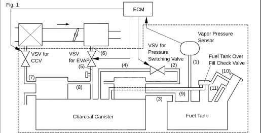
(11) Fig. 1
VSV for CCV
VSV for EVAP
ECM
Vapor Pressure Sensor
Fuel Tank Over Fill Check Valve
Fuel Tank Charcoal Canister
VSV for Pressure Switching Valve
A73631
DTC
P0442
EVAPORATIVE EMISSION CONTROL
SYSTEM LEAK DETECTED (SMALL LEAK)
DTC
P0456
EVAPORATIVE EMISSION CONTROL
SYSTEM LEAK DETECTED (VERY SMALL
LEAK)
CIRCUIT DESCRIPTION
The vapor pressure sensor andthe VSV for the canister closed valve (CCV) are used to detect abnormalities in the evaporative emission control system. The ECM decides whether there is an abnormality in the evapo-rative emission control system based on the vapor pressure sensor signal.
[image:1.595.40.555.293.555.2]A73632
VSV for CCV
VSV for
Pressure Switching Valve
VSV for EVAP
Cold Start
Temperatures of the engine coolant and the intake air are almost equal.
Negative Pressure Introduction
Tank & Canister Leak Check
VSV for Pressure Switching Valve, CCV Testing Open Closed Open Closed Open Closed Closed Closed Open
P0441 P0442, P0456 P0446 Inner pressure in the tank
384
Author: Date:
2004 COROLLA (RM1037U)
DTC No. DTC Detection Condition Trouble Area
P0442 After negative pressure introduction is completed, if the pres-sure in the EVAP system sharply increases. (small leak) (2 trip detection logic)
Vacuum hose has cracks, holes, or is blocked, damaged or disconnected
Fuel tank cap incorrectly installed Fuel tank cap has cracks or is damaged Open or short in vapor pressure sensor circuit Vapor pressure sensor
Open or short in VSV circuit for EVAP
P0456 If the pressure in the EVAP system slightly increases while the ECM performs a leak check. (very small leak) (2 trip detection logic)
O en or short in VSV circuit for EVAP VSV for EVAP
Open or short in VSV circuit for CCV VSV for CCV
Fuel tank has cracks, holes, or is damaged Charcoal canister has cracks, holes, or is damaged Fuel tank over fill check valve cracks, or is damaged ECM
HINT:
Typical DTC output of each trouble part.
Trouble part Typical DTC output (*1) Small Leak P0442 and/or P0456 (*2) Medium Leak (ex: Vacuum hose loose) P0442
Large Leak (ex: Fuel tank cap loose) P0441 and P0442 and P0446
VSV for EVAP
Open Malfunction P0441 VSV for EVAP
Close Malfunction P0441 and P0442 and P0446
VSV for CCV
Open Malfunction P0441 and P0442 and P0446 VSV for CCV
Close Malfunction P0446
VSV for Pressure Switching Open Malfunction P0446 VSV for Pressure Switching
Close Malfunction P0441 and P0442 and P0446
*1: ECM may output some other DTCs combination.
MONITOR DESCRIPTION
The evaporative emission system consists of the vapor pressure sensor, the canister close valve (CCV), the VSV for pressure switching valve and the VSV for EVAP (Purge VSV), those are used to detect malfunction in the system by ECM.
This test will run once per driving cycle when the ECM detects stable vapor pressure in the fuel tank. While the vehicle is being driven on rough or winding roads, the movement of the fuel in the tank will cause unstable fuel tank vapor pressures and the diagnostic test will not executed.
The ECM performs the following steps:
(a) The CCV is closed. (shutting the system)
(b) The fuel tank pressure stability is checked. The diagnostic is disabled if the pressure change is more than specified value.
(c) The VSV for EVAP is opened. This introduces a negative pressure from the intake manifold to the fuel tank.
(d) The VSV for EVAP is closed and the negative pressure is sealed in the fuel tank. (e) The ECM monitors the increase in fuel tank pressure for:
(1) Rapid increase in the internal pressure i.e. a large leak: 0.040 or more (2) Pressure rise just above normal
If the ECM detects either of above conditions, it will interpret this as a leak in the EVAP system. The ECM will illuminate the MIL (2–trip detection logic) and set a DTC.
MONITOR STRATEGY
DTCs P0442 Small leak (0.040 inch or more hole) detected DTCs
P0456 Very small leak (0.020 inch hole) detected Main Vapor pressure sensor
Required sensors/components
Sub
Mass air flow sensor, engine coolant temperature sensor, VSV for EVAP (purge VSV), VSV for CCV
Frequency of operation Once per drive cycles Duration 60 seconds
MIL operation 2 drive cycles Sequence of operation None
TYPICAL ENABLING CONDITIONS
Item Criteria
Item
Minimum Maximum
The monitor will run whenever the
follow-ing DTCs are not present See ”List of Disable a monitor” (On page 05–25)
Common pre–conditions for 0.020 and 0.040 inch:
Altitude – 2,400 m (7,872 ft.)
Throttle position learning Completed Vapor pressure sensor No malfunction Difference between intake air temperature
and engine coolant temperature at engine start.
–7C (–19.4F) 11.1C (52F)
386
Author: Date:
2004 COROLLA (RM1037U)
Intake air temperature 10C (50F) – Fuel level condition in fuel tank during leak
check Fuel slosh is small (must not drive on road with bad conditions)
Time after engine start – 50 minutes
Fuel tank pressure condition before leak check (Fuel tank condition before closed negative pressure introduction)
Fuel tank internal pressure change is small before negative pressure introduction.
(Reference: If fuel in the tank is high temperature, vapor volume increase and the internal pressure changes also increase)
Vehicle speed and intake air amount condition before and after negative pres-sure introduction
Steady speed and not change greatly of intake air amount
Fuel level – 90%
0.020 inch leak detection Not completed 0.040 inch leak detection Not detected VSV for CCV malfunction, bypass VSV
malfunction Not detected
Vehicle speed – 81 mph (130 km/h)
VSV for EVAP (Evap purge VSV)
mal-function Not detected
0.040 inch malfunction:
Engine coolant temperature at engine
start 10C (50F) 35C (95F)
Intake air temperature at engine start 10C (50F) 35C (95F) Intake air temperature 10C (50F) – Fuel level condition in fuel tank during leak
check Fuel slosh is small (must not drive on road with bad conditions)
Time after engine start – 50min
Fuel tank pressure condition before leak check (Fuel tank condition before closed negative pressure introduction)
Fuel tank internal pressure change is small before negative pressure introduction.
(Reference: If fuel in the tank is high temperature, vapor volume increase and the internal pressure changes also increase)
Vehicle speed and intake air amount condition before and after negative pres-sure introduction
Steady speed and not change greatly of intake air amount
Fuel level – 90%
0.040 inch leak detection Not completed Fuel tank pressure at vacuum introduction
completed –2.4 kPa (–18 mmHg) –
P0446 VSV check No executed
TYPICAL MALFUNCTION THRESHOLDS
Detection Criteria Threshold
0.020 inch malfunction detection:
Fuel tank pressure changing value, from –2.0 kPa (–15
mmHg), for 5 seconds Increase more than 0.067 kPa (0.5 mmHg) Fuel tank pressure changing value, from –2.7 kPa (–20
mmHg), for 5 seconds Increase more than 0.067 kPa (0.5 mmHg)
0.040 inch malfunction detection:
Fuel tank pressure changing value, from –2.0 kPa (–15
mmHg), for 5 seconds Increase more than 0.24 kPa (1.8 mmHg) Fuel tank pressure changing value, from –2.7 kPa (–20
MONITOR RESULT (MODE 06 DATA)
Test ID Comp ID Description of Test Data Description of Test Limit Unit Conversion Factor
$81 Tank pressure change value dur-ing vacuum introduction
Malfunction criteria for VSV for
EVAP mmHg
Multiply by 0.0916
$82
Fuel tank pressure change value at switching over the canister close valve or VSV for pressure switching valve.
Malfunction criteria for canister close valve and VSV for pressure
switching valve
mmHg
Multiply by 0.0458 minus
2.930
$02
$03
Fuel tank pressure change 5 se-conds after the end the vacuum introduction cycle
Conditions:
Malfunction criteria for 0.040 leak mmHg Multiply by 0.0458
$04
Conditions:
VSV for EVAP: Closed CCV: Closed
VSV for bypass valve: Open
Malfunction criteria for 0.020 leak mmHg Multiply by 0.0458
Refer to page 05–27 for detailed information on Checking Monitor Status.
INSPECTION PROCEDURE
Hand–held Tester:
1
CHECK FUEL TANK CAP ASSY(CHECK THAT FUEL TANK CAP IS TOYOTA
GENUINE PARTS)
NG REPLACE TO TOYOTA GENUINE PARTS
OK
2
CHECK THAT FUEL TANK CAP IS CORRECTLY INSTALLED
NG CORRECTLY INSTALL FUEL TANK CAP
OK
3
INSPECT FUEL TANK CAP ASSY (See page
12–1
)
NG REPLACE FUEL TANK CAP ASSY
OK
4
CHECK FILLER NECK FOR DAMAGE
(a) Remove the fuel tank cap.
A65767
VSV is OFF VSV is ON
Air Air
388
Author: Date:
2004 COROLLA (RM1037U)
5
PERFORM ACTIVE TEST BY HAND–HELD TESTER(CHECK FOR EVAP PURGE
FLOW)
(a) Select the item ”DIAGNOSIS/ENHANCED OBD
II/AC-TIVE TEST” mode on the hand–held tester.
(b) Disconnect the vacuum hose of the VSV for EVAP from
the charcoal canister. (c) Start the engine.
(d) Select the item ”EVAP VSV (ALON)/ALL” in the ACTIVE
TEST and operate EVAP VSV (Press the right or left but-ton).
(e) When the VSV for the EVAP is operated by the hand–held tester, check whether the disconnected hose applies suc-tion to your finger.
Result:
VSV is ON: Disconnected hose sucks.
VSV is OFF: Disconnected hose does not suck.
(f) Reconnect the vacuum hose.
OK Go to step 9
NG
6
CHECK VACUUM HOSES(INTAKE MANIFOLD – VSV FOR EVAP, VSV FOR EVAP –
CHARCOAL CANISTER)
(a) Check that the vacuum hose is connected correctly.
(b) Check the vacuum hose for looseness and disconnection.
(c) Check the vacuum hose for cracks, hole, damage and blockage.
NG REPAIR OR REPLACE VACUUM HOSE
OK
7
INSPECT VSV FOR EVAP(OPERATION) (See page
12–1
)
NG REPLACE VSV FOR EVAP
A51984 A52933
Wire Harness Side:
VSV for EVAP Connector V3
Front View
A65743
EVP E3
ECM Connector
A65750
Engine Room R/B:
EFI Relay
8
CHECK HARNESS AND CONNECTOR(EFI RELAY – VSV FOR EVAP, VSV FOR
EVAP – ECM)
(a) Check the harness and the connector between the VSV
for EVAP and ECM.
(1) Disconnect the V3 VSV for EVAP connector.
(2) Disconnect the E3 ECM connector.
(3) Check the resistance between the wire harness
side connectors.
Standard (Check for open):
Tester Connection Specified Condition VSV for EVAP (V3–1) – EVP (E3–12) Below 1 Ω Standard (Check for short):
Tester Connection Specified Condition VSV for EVAP (V3–1) or EVP (E3–12) – Body ground 10 kΩ or higher
(4) Reconnect the VSV for EVAP connector.
(5) Reconnect the ECM connector.
(b) Check the harness and the connector between the VSV
for EVAP and EFI relay.
(1) Disconnect the V3 VSV for EVAP connector.
(2) Remove the EFI relay from the engine room R/B.
(3) Check the resistance between the wire harness
side connectors.
Standard (Check for open):
Tester Connection Specified Condition VSV for EVAP (V3–2) – EFI relay (3) Below 1 Ω Standard (Check for short):
Tester Connection Specified Condition VSV for EVAP (V3–2) or EFI relay (3) – Body ground 10 kΩ or higher
(4) Reconnect the VSV for EVAP connector.
(5) Reinstall the EFI relay.
NG REPAIR OR REPLACE HARNESS OR CONNECTOR
OK
A65768
VSV is OFF VSV is ON
Air E Air
F
E
F
390
Author: Date:
2004 COROLLA (RM1037U)
9
PERFORM ACTIVE TEST BY HAND–HELD TESTER(VSV FOR CCV)
(a) Disconnect the vacuum hose of the VSV for CCV from the charcoal canister.
(b) Start the engine.
(c) Select the item ”DIAGNOSIS/ENHANCED OBD
II/AC-TIVE TEST” mode on the hand–held tester.
(d) Select the item ”CAN CTRL VSV/ALL” in the ACTIVE
TEST and operate CAN CTRL VSV (Press the right or left button).
(e) Check the VSV operation when it is operated by the
hand–held tester.
Result:
VSV is ON: Air from port E flows out through port F. VSV is OFF: Air does not flow from port E to port F.
OK Go to step 13
NG
10
CHECK VACUUM HOSES(VSV FOR CCV – CHARCOAL CANISTER)
(a) Check that the vacuum hose is connected correctly.
(b) Check the vacuum hose for looseness and disconnection.
(c) Check the vacuum hose for cracks, hole damage and blockage.
NG REPAIR OR REPLACE VACUUM HOSES
OK
11
INSPECT VSV FOR CCV(OPERATION) (See page
12–6
)
NG REPLACE VSV FOR CCV
A54386
Wire Harness Side:
VSV for CCV Connector
V2
Front View
A65744
CCV ECM Connector
E5
A65750
Engine Room R/B:
EFI Relay
12
CHECK HARNESS AND CONNECTOR(EFI RELAY – VSV FOR CCV, VSV FOR CCV
– ECM)
(a) Check the harness and connector between the VSV for
CCV and ECM.
(1) Disconnect the V2 VSV for CCV connector.
(2) Disconnect the E5 ECM connector.
(3) Check the resistance between the wire harness
side connectors.
Standard (Check for open):
Tester Connection Specified Condition VSV for CCV (V2–1) – CCV (E5–1) Below 1 Ω
Tester Connection Specified Condition VSV for CCV (V2–1) or CCV (E5–1) – Body ground 10 kΩ or higher
(4) Reconnect the VSV for CCV connector.
(5) Reconnect the ECM connector.
(b) Check the harness and the connector between the VSV
for CCV and EFI relay.
(1) Disconnect the V2 VSV for CCV connector.
(2) Remove the EFI relay from the engine room R/B.
(3) Check the resistance between the wire harness
side connectors.
Standard (Check for open):
Tester Connection Specified Condition VSV for CCV (V2–2) – EFI relay (3) Below 1 Ω Standard (Check for short):
Tester Connection Specified Condition VSV for CCV (V2–2) or EFI relay (3) – Body ground 10 kΩ or higher
(4) Reconnect the VSV for CCV connector.
(5) Reinstall the EFI relay.
NG REPAIR OR REPLACE HARNESS OR CONNECTOR
OK
Air
E
F Air
E
F
VSV is ON VSV is OFF
A52984
392
Author: Date:
2004 COROLLA (RM1037U)
13
PERFORM ACTIVE TEST BY HAND–HELD TESTER(VSV FOR PRESSURE
SWITCHING VALVE)
(a) Select the item ”DIAGNOSIS/ENHANCED OBD
II/AC-TIVE TEST” mode on the hand–held tester.
(b) Select the item ”TANK BYPASS VSV/ALL” in the ACTIVE
TEST and operate TANK BYPASS VSV (Press the right or left button).
(c) Check the VSV operation when it is operated by the
hand–held tester.
Result:
VSV is ON: Air from port E flows out through port F. VSV is OFF: Air does not flow from port E to port F.
OK Go to step 16
NG
14
INSPECT VSV FOR PRESSURE SWITCHING VALVE(OPERATION)
NG REPLACE VSV FOR PRESSURE SWITCHING VALVE
A72890
Wire Harness Side:
VSV for Pressure Switching Valve
V5
Front View
A65748
ECM Connector E6
TBP
A65750
Engine Room R/B:
EFI Relay
15
CHECK HARNESS AND CONNECTOR(EFI RELAY – VSV FOR PRESSURE
SWITCHING VALVE, VSV FOR PRESSURE SWITCHING VALVE – ECM)
(a) Check the harness and the connector between the VSV
for pressure switching valve and the ECM.
(1) Disconnect the V5 VSV for pressure switching valve connector.
(2) Disconnect the E6 ECM connector.
(3) Check the resistance between the wire harness
side connectors.
Standard (Check for open):
Tester Connection Specified Condition VSV for pressure switching valve (V5–1) – TBP (E6–4) Below 1 Ω
Standard (Check for short):
Tester Connection Specified Condition VSV for pressure switching valve (V5–1) or TBP (E6–4)
– Body ground 10 kΩ or higher
(4) Reconnect the VSV for pressure switching valve
connector.
(5) Reconnect the ECM connector.
(b) Check the harness and the connector between the VSV
for pressure switching valve and EFI relay.
(1) Disconnect the V5 VSV for pressure switching valve connector.
(2) Remove the EFI relay from the engine room R/B.
(3) Check the resistance between the wire harness
side connectors.
Standard (Check for open):
Tester Connection Specified Condition VSV for pressure switching valve (V5–2) – EFI relay (3) Below 1 Ω
Standard (Check for short):
Tester Connection Specified Condition VSV for pressure switching valve (V5–2) or EFI relay (3)
– Body ground 10 kΩ or higher
(4) Reconnect the VSV for pressure switching valve
connector.
(5) Reinstall the EFI relay.
NG REPAIR OR REPLACE HARNESS OR CONNECTOR
OK
A10193
A65741
VC (+)
E2 (–) E3
ECM Connector
394
Author: Date:
2004 COROLLA (RM1037U)
16
CHECK FOR EVAPORATIVE EMISSIONS LEAK(NEAR FUEL TANK)
(a) Check whether hoses close to the fuel tank have been
modified, and check if there are signs of any accident near the fuel tank.
(1) Check the following parts for cracks, deformation or loose connection:
Fuel tank
Fuel tank filler pipe
Hoses and tubes around fuel tank
NG REPAIR OR REPLACE EVAPORATIVE EMISSIONS LEAK PART
OK
17
CHECK VACUUM HOSES(VAPOR PRESSURE SENSOR – FUEL TANK,
CHARCOAL CANISTER – VSV FOR PRESSURE SWITCHING VALVE)
(a) Check that the vacuum hose is connected correctly.
(b) Check the vacuum hose for looseness and disconnection.
(c) Check the vacuum hose for cracks, hole and damage.
NG REPAIR OR REPLACE VACUUM HOSE
OK
18
CHECK HOSE AND TUBE(FUEL TANK – CHARCOAL CANISTER)
(a) Check the connection between the fuel tank and fuel EVAP pipe, the fuel EVAP pipe and under floor fuel tube, the under floor fuel tube and charcoal canister.
(b) Check the hose and the tube for cracks, hole and damage.
NG REPAIR OR REPLACE HOSE AND TUBE
OK
19
INSPECT ECM(VC VOLTAGE)
(a) Turn the ignition switch ON.
(b) Measure the voltage between the terminals of the E3
ECM connector.
Standard:
Tester Connection Specified Condition VC (E3–18) – E2 (E3–28) 4.5 to 5.5 V
NG REPLACE ECM (See page 10–11)
A65741
E2 (–) PTNK (+)
E3 E6
A73630
Disconnect TYPE A
TYPE B
Vacuum Vacuum
Disconnect
A72886
Wire Harness Side:
Vapor Pressure Sensor Connector
GND PTNK VCC
V4
Front View
E6 E3
VC
20
INSPECT ECM(PTNK VOLTAGE)
(a) Turn the ignition switch ON.
(b) Measure the voltage between terminals of the E3 and E6 ECM connectors.
(1) Disconnect the vacuum hose from the vapor
pres-sure sensor.
Standard (1):
Tester Connection Specified Condition PTNK (E6–21) – E2 (E3–28) 2.9 to 3.7 V NOTICE:
The vacuum applied to the vapor pressure sensor must be less than 66.7 kPa (500 mmHg, 19.7 in.Hg).
(2) Using the MITYVAC (Hand–held Vacuum Pump),
apply a vacuum of 4.0 kPa (30 mmHg, 1.18 in.Hg) to the vapor pressure sensor.
Standard (2):
Tester Connection Specified Condition PTNK (E6–21) – E2 (E3–28) 0.5 V or less
(3) Reconnect the vacuum hose.
OK Go to step 22
NG
21
CHECK HARNESS AND CONNECTOR(VAPOR PRESSURE SENSOR – ECM)
(a) Disconnect the V4 vapor pressure sensor connector.
(b) Disconnect the E3 and E6 ECM connectors.
(c) Check the resistance between the wire harness side con-nectors.
Standard (Check for open):
Tester Connection Specified Condition PTNK (V4–2) – PTNK (E6–21)
GND (V4–1) – E2 (E3–28) Below 1 Ω VCC (V4–3) – VC (E3–18)
Standard (Check for short):
Tester Connection Specified Condition PTNK (V4–2) or PTNK (E6–21) – Body ground
10 kΩor higher VCC (V4–3) or VC (E3–18) – Body ground 10 kΩ or higher
(d) Reconnect the vapor pressure sensor connector.
396
Author: Date:
2004 COROLLA (RM1037U)
REPLACE ECM (See page 10–11)
22
INSPECT FUEL TANK INLET VALVE ASSY
NG REPLACE FUEL TANK INLET VALVE ASSY
OK
23
INSPECT FUEL TANK ASSY
NG REPLACE FUEL TANK ASSY
OK
24
INSPECT CHARCOAL CANISTER ASSY(CRACKS, HOLE AND DAMAGE)
NG REPAIR OR REPLACE CHARCOAL CANISTER ASSY
OK
REPLACE ECM (See page 10–11)
OBDII scan tool (excluding Hand–held Tester):
1
CHECK FUEL TANK CAP ASSY(CHECK THAT FUEL TANK CAP IS TOYOTA
GEHUINE PARTS)
NG REPLACE TO GENUINE PARTS
OK
2
CHECK THAT FUEL TANK CAP IS CORRECTLY INSTALLED
NG CORRECTLY INSTALL FUEL TANK CAP
OK
3
INSPECT FUEL TANK CAP ASSY (See page
12–1
)
NG REPLACE FUEL TANK CAP ASSY
A10193
4
CHECK FILLER NECK FOR DAMAGE
(a) Remove the fuel tank cap.
(b) Visually check the fuel inlet pipe for damage.
NG REPLACE FUEL TANK INLET PIPE SUB–ASSY
OK
5
CHECK FOR EVAPORATIVE EMISSIONS LEAK(NEAR FUEL TANK OR CHACOAL
CANISTER)
(a) Check whether hoses close to the fuel tank have been
modified, and check if there are signs of any accident near the fuel tank or the charcoal canister.
(1) Check the following parts for cracks, deformation or loose connection:
Fuel tank
Charcoal canister
Fuel tank filler pipe
Hoses and tubes around fuel tank and
char-coal canister
NG REPAIR OR REPLACE EVAPORATIVE EMISSIONS LEAK PART
OK
6
CHECK VACUUM HOSES(VAPOR PRESSURE SENSOR – FUEL TANK,
CHARCOAL CANISTER – VSV FOR PRESSURE SWITCHING VALVE)
(a) Check that the vacuum hose is connected correctly.
(b) Check the vacuum hose for looseness and disconnection.
(c) Check the vacuum hose for cracks, hole and damage.
NG REPAIR OR REPLACE VACUUM HOSE
OK
7
CHECK HOSE AND TUBE(FUEL TANK – CHARCOAL CANISTER)
(a) Check the connection between the fuel tank and fuel EVAP pipe, the fuel EVAP pipe and under floor fuel tube, the under floor fuel tube and charcoal canister.
(b) Check the hose and the tube for cracks, hole and damage.
A65741
VC (+)
E2 (–) E3
ECM Connector
398
Author: Date:
2004 COROLLA (RM1037U)
8
CHECK VACUUM HOSES((5), (6), (7), (8) AND (9) IN FIG. 1 IN CIRCUIT
DESCRIPTION)
(a) Check that the vacuum hose is connected correctly.
(b) Check the vacuum hose for looseness and disconnection.
(c) Check the vacuum hose for cracks, hole and damage.
NG REPAIR OR REPLACE VACUUM HOSES
OK
9
CHECK EACH VSV CONNECTOR FOR LOOSENESS AND DISCONNECTION(VSV
FOR EVAP, VSV FOR CCV, VSV FOR PRESSURE SWITCHING VALVE)
NG REPAIR OR CONNECT VSV AND SENSOR CONNECTOR
OK
10
INSPECT CHARCOAL CANISTER ASSY(CRACKS, HOLE AND DAMAGE)
NG CHECK AND REPLACE CHARCOAL CANISTER ASSY
OK
11
INSPECT ECM(VC VOLTAGE)
(a) Turn the ignition switch ON.
(b) Measure voltage between the terminals of the E3 ECM
connector.
Standard:
Tester Connection Specified Condition VC (E3–18) – E2 (E3–28) 4.5 to 5.5 V
NG REPLACE ECM (See page 10–11)
A65741
E2 (–) PTNK (+)
E3 E6
A73630
Disconnect TYPE A
TYPE B
Vacuum Vacuum
Disconnect
12
INSPECT ECM(PTNK VOLTAGE)
(a) Turn the ignition switch ON.
(b) Measure the voltage between terminals of the E3 and E6 ECM connectors.
(1) Disconnect the vacuum hose from the vapor
pres-sure sensor.
Standard (1):
Tester Connection Specified Condition PTNK (E6–21) – E2 (E3–28) 2.9 to 3.7 V NOTICE:
The vacuum applied to the vapor pressure sensor must be less than 66.7 kPa (500 mmHg, 19.7 in.Hg).
(2) Using the MITYVAC (Hand–held Vacuum Pump),
apply a vacuum of 4.0 kPa (30 mmHg, 1.18 in.Hg) to the vapor pressure sensor.
Standard (2):
Tester Connection Specified Condition PTNK (E6–21) – E2 (E3–28) 0.5 V or less
(3) Reconnect the vacuum hose from the vapor
pres-sure sensor.
OK Go to step 14
A72886
Wire Harness Side:
Vapor Pressure Sensor Connector
GND PTNK VCC
V4
Front View
A79127
E6 E3
ECM Connector E2
VC
PTNK
A65741
E2 (–) EVP (+)
E3
A65767
VSV is ON VSV is OFF E
F
E
F
Air Air
400
Author: Date:
2004 COROLLA (RM1037U)
13
CHECK HARNESS AND CONNECTOR(VAPOR PRESSURE SENSOR – ECM)
(a) Disconnect the V4 vapor pressure sensor connector.
(b) Disconnect the E3 and E6 ECM connectors.
(c) Check the resistance between the wire harness side con-nectors.
Standard (Check for open):
Tester Connection Specified Condition PTNK (V4–2) – PTNK (E6–21)
GND (V4–1) – E2 (E3–28) Below 1 Ω VCC (V4–3) – VC (E3–18)
Standard (Check for short):
Tester Connection Specified Condition PTNK (V4–2) or PTNK (E6–21) – Body ground
10 kΩor higher VCC (V4–3) or VC (E3–18) – Body ground 10 kΩ or higher
(d) Reconnect the vapor pressure sensor connector.
(e) Reconnect the ECM connectors.
NG REPAIR OR REPLACE HARNESS OR CONNECTOR
OK
REPLACE ECM (See page 10–11)
14
INSPECT VSV FOR EVAP(FUNCTION)
(a) Turn the ignition switch ON.
(b) Check the VSV function.
(1) Connect between terminals EVP and E2 of the
ECM connector (VSV ON).
VSV is ON:
Air from port E flows out through port F
(2) Disconnect between terminals EVP and E2 of the
ECM connector (VSV OFF).
VSV is OFF:
Air does not flow port E to port F
OK Go to step 17
A51984 A52933
Wire Harness Side:
VSV for EVAP Connector
V3
Front View
A65743
EVP E3
ECM Connector
A65750
Engine Room R/B:
EFI Relay
15
INSPECT VSV FOR EVAP(OPERATION) (See page
12–6
)
NG REPLACE VSV FOR EVAP
OK
16
CHECK HARNESS AND CONNECTOR(EFI RELAY – VSV FOR EVAP, VSV FOR
EVAP – ECM)
(a) Check the harness and connector between the VSV for
EVAP and ECM.
(1) Disconnect the V3 VSV for EVAP connector.
(2) Disconnect the E3 ECM connector.
(3) Check the resistance between the wire harness
side connectors.
Standard (Check for open):
Tester Connection Specified Condition VSV for EVAP (V3–1) – EVP (E3–12) Below 1 Ω Standard (Check for short):
Tester Connection Specified Condition VSV for EVAP (V3–1) or EVP (E3–12) – Body ground 10 kΩ or higher
(4) Reconnect the VSV for EVAP connector.
(5) Reconnect the ECM connector.
(b) Check the harness and connector between the VSV for
EVAP and EFI relay.
(1) Disconnect the V3 VSV for EVAP connector.
(2) Remove the EFI relay from the engine room R/B.
(3) Check the resistance between the wire harness
side connectors.
Standard (Check for open):
Tester Connection Specified Condition VSV for EVAP (V3–2) – EFI relay (3) Below 1 Ω Standard (Check for short):
Tester Connection Specified Condition VSV for EVAP (V3–2) or EFI relay (3) – Body ground 10 kΩ or higher
(4) Reconnect the VSV for EVAP connector.
(5) Reinstall the EFI relay.
A53763
E2
CCV
A65768
VSV is ON VSV is OFF E
F
E
F
Air Air
402
Author: Date:
2004 COROLLA (RM1037U)
17
INSPECT VSV FOR CCV(FUNCTION)
(a) Turn the ignition switch ON.
(b) Check the VSV function.
(1) Connect between terminals CCV and E2 of the
ECM connector (VSV ON).
VSV is ON:
Air from port E flows out through port F
(2) Disconnect between terminals CCV and E2 of the
ECM connector (VSV OFF).
VSV is OFF:
Air does not flow from port E to port F
OK Go to step 20
NG
18
INSPECT VSV FOR CCV(OPERATION) (See page
12–6
)
NG REPLACE VSV FOR CCV
A54386
Wire Harness Side:
VSV for CCV Connector
V2
Front View
A65750
Engine Room R/B:
EFI Relay
A65744
CCV
ECM Connector E5
19
CHECK HARNESS AND CONNECTOR(EFI RELAY – VSV FOR CCV, VSV FOR CCV
– ECM)
(a) Check the harness and the connector between the VSV
for CCV and ECM.
(1) Disconnect the V2 VSV for CCV connector.
(2) Disconnect the E5 ECM connector.
(3) Check the resistance between the wire harness
side connectors.
Standard (Check for open):
Tester Connection Specified Condition VSV for CCV (V2–1) – CCV (E5–1) Below 1 Ω Standard (Check for short):
Tester Connection Specified Condition VSV for CCV (V2–1) or CCV (E5–1) – Body ground 10 kΩ or higher
(4) Reconnect the VSV for CCV connector.
(5) Reconnect the ECM connector.
(b) Check the harness and the connector between the VSV
for CCV and EFI relay.
(1) Disconnect the V2 VSV for CCV connector.
(2) Remove the EFI relay from the engine room R/B.
(3) Check the resistance between the wire harness
side connectors.
Standard (Check for open):
Tester Connection Specified Condition VSV for CCV (V2–2) – EFI relay (3) Below 1 Ω Standard (Check for short):
Tester Connection Specified Condition VSV for CCV (V2–2) or EFI relay (3) – Body ground 10 kΩ or higher
(4) Reconnect the VSV for CCV connector.
(5) Reinstall the EFI relay.
NG REPAIR OR REPLACE HARNESS OR CONNECTOR
OK
A65741
E2 TBP
E6 E3
VSV is ON VSV is OFF Air
E
F
Air
E
F
A52143
404
Author: Date:
2004 COROLLA (RM1037U)
20
INSPECT VSV FOR PRESSURE SWITCHING VALVE(FUNCTION)
(a) Turn the ignition switch ON.
(b) Check the VSV function.
(1) Connect between terminals TBP and E2 of the ECM
connector (VSV ON).
VSV is ON: Air from port E flows out through port F
(2) Disconnect between terminals TBP and E2 of the
ECM connector (VSV OFF).
VSV is OFF: Air does not from flow port E to port F
OK Go to step 23
NG
21
INSPECT VSV FOR PRESSURE SWITCHING VALVE(OPERATION)
(See page
12–6
)
NG REPLACE VSV FOR PRESSURE SWITCHING VALVE
A72890
Wire Harness Side:
VSV for Pressure Switching Valve
V5
Front View
A65748
ECM Connector E6
TBP
A65750
Engine Room R/B:
EFI Relay
22
CHECK HARNESS AND CONNECTOR(EFI RELAY – VSV FOR PRESSURE
SWITCHING VALVE, VSV FOR PRESSURE SWITCHING VALVE – ECM)
(a) Check the harness and the connector between the VSV
for pressure switching valve and ECM.
(1) Disconnect the V5 VSV for pressure switching valve connector.
(2) Disconnect the E6 ECM connector.
(3) Check the resistance between the wire harness
side connectors.
Standard (Check for open):
Tester Connection Specified Condition VSV for pressure switching valve (V5–1) – TBP (E6–4) Below 1 Ω
Standard (Check for short):
Tester Connection Specified Condition VSV for pressure switching valve (V5–1) or TBP (E6–4)
– Body ground 10 kΩ or higher
(4) Reconnect the VSV for pressure switching valve
connector.
(5) Reconnect the ECM connector.
(b) Check the harness and the connector between the VSV
for pressure switching valve and EFI relay.
(1) Disconnect the V5 VSV for pressure switching valve connector.
(2) Remove the EFI relay from the engine room R/B.
(3) Check the resistance between the wire harness
side connectors.
Standard (Check for open):
Tester Connection Specified Condition VSV for pressure switching valve (V5–2) – EFI relay (3) Below 1 Ω
Standard (Check for short):
Tester Connection Specified Condition VSV for pressure switching valve (V5–2) or EFI relay (3)
– Body ground 10 kΩ or higher
(4) Reconnect the VSV for pressure switching valve
connector.
(5) Reinstall the EFI relay from.
NG REPAIR OR REPLACE HARNESS OR CONNECTOR
OK
406
Author: Date:
2004 COROLLA (RM1037U)
23
INSPECT FUEL TANK INLET VALVE ASSY
NG REPLACE FUEL TANK INLET VALVE ASSY
OK
24
INSPECT FUEL TANK ASSY
NG REPLACE FUEL TANK ASSY
OK