Abstract—Mandibular fracture is increasingly treated with fixing plate instead of wire sawing in order to retrieve jaw functionality. Fixing plate need to as light as possible, yet the long fatigue life is a must. Non-parametric optimization-based design has been implemented in this work to achieve long fatigue life. Mandibular has been simulated using finite element method from computed tomography scan. In order to achieve long fatigue life plate with minimal weight, cascade Non-parametric optimization modeling is implemented in two stages. First stage is stress based optimization. The second stage is fatigue based stress optimization. In the first stage, the comparison between shape and topology optimization. Fist cascade model (Stress based topology-Fatigue based optimization) gave the better results in term of weight reduction (45%) while the second cascade model (Stress based shape-fatigue based optimization) doubled the fatigue life.
Index Terms—Fatigue, TMJ, topology optimization, shape optimization.
I. INTRODUCTION
esigning artificial body parts to help healing or replace permanently damage organs is a challenge for physician and engineers. The way of approaching the problem will vary, with the designer experience and way of thinking. Mostly there are two way of thinking in the matter of scaffold design; the strictly Engineering aspects, like manufacturing aspects, compliance and mechanical failure approaches, and simplified models. The other was is the strictly biological way, post and pre-observation of problem in hand, before and after surgical intervenes. Bone considered the hard parts in body which protecting the physical appearance of soft organs internally or externally i.e. limps, and brain. Body may suffer external stress causing fragmentation of bone, as motorcycle incidents, and so on; or physiological disorder, making normal stresses able to destroy the bone. Orthopaedist vision of treatments with extra aided parts, they have temporary surgical fixation mechanical parts and in sever case permanent implant should use. The difference between these two is due to Muazez Al Ali M.Sc. is a lecturer in Al Ayen University / College of Dentistry, Iraq ThiQar (email [email protected] )
Rajaa S. Abass is a lecturer at Al Mamon University College, 14 Ramadan St., Baghdad, Iraq (e-mail: [email protected] ).
Musaddiq Al Ali PhD, Comtech corporation, Hiroshima, Japan (e-mail:
Amjad Y. Sahib, is a lecturer at University of Wasit, college of engineering, Wasit Province, Hay Al Rabee, Kut, Iraq (email:
biomechanical interaction. For example, in case of implants, permanent parts usually be metallic to endure static and dynamic failure criterion, however, stiffness mismatching cause stress shielding in surrounding bone. Attachments stability in small implants such as dental implants is also important mater for designing implant surface. Although Temporary fixation part doesn’t priorities previous aspects, it needs to be light weight as much as possible with propitiate mechanical endurance during operating time. The purpose of the present work is to plot scheme based on stress constraint - topology optimization (TO) taking into consideration elastic failure criterion. Stress based topology optimization (SBTO) is demanded topics; studied by many searches as. For certain application such as in biological filed” bone replacement and scaffold), design domain Ω is limited by the surrounding fixed materials domain, and in some cases, with different mechanical behavior. The major issue in applied mechanics point of view is the mechanical compatibility between design domain and surrounding domain. Implant design is divided it short term “temporary “implants and long term” permanent” implants. The current work focuses on the first type. Light weight with high strength is a target for such parts.
II. FATIGUE
Static consideration of stress-strain problem is the most common way of handling mechanical designs. However, dynamic loading tends to give a failure is not a predictable way (in the scope of previously mentioned static yielding criteria). The word “fatigue” used to describe the unexplained failure which done by reversed dynamic loading. With the development of steam engines, railroad axels, for example, are failed after the relatively short term of service. This made many scientific societies in Europe work independently to study this phenomenon. Especially after the disaster of Versailles rail accident in France. It is being registered that the first simulation apparatus of fatigue has been made by Albert in German Confederation (1829). Since 1841 the fatigue subject was studied intensively by Rankine in the United Kingdom followed by Wohler in Germany. Wohler invented his testing apparatus with which he established the timeless prediction of fatigue, distinguishing the fatigue from creep. As been said, about science that it is not always where what the scientist wants it to be, Wohler established the following remarks for the first time.
1- The number of stress cycles is the fact of determining failure rather than test elapsed time.
Fatigue Life Extending For Temporomandibular
Plate Using Non Parametric Cascade
Optimization
Muazez Al Ali, Musaddiq Al Ali, Rajaa S. Saleh, Amjad Y. Sahib
2- Ferrous materials with stress loading below a certain limit (endurance limit) can withstand loading indefinitely Simply fatigue failure has three stages, crack nucleation, crack propagation, and finally fracture. Crack propagation approach considered the logical approach since fatigue is a result of the crack in the first place. Moreover, it has been noticed that crack initiations period may cover most of fatigue life; especially in high cycle fatigue (HCF). As more detailed consideration of fatigue problem especially for metals, it states with localized plastic strain, cyclic hardening and softening, the followed by more visible failure i.e. crack initiation and the repetition of the previously mentioned cycle which introduced the crack growth. Slip bands are done as an action representing the plastic strain. it has been noticed that slip behavior is intricately linked to the metal structure and strain conditions. So, slip anticipated to occur along the plane of the densest atoms (Figure.9). It is worth to mention that slip is not a straightforward process. Slip lines can be complicated, taking curvy lines or even cross slip. This is happening due to obstacles and crystal defects[1]. Generally, in one phase metals, slip bands are the main source of micro crack. The surface layer is the anticipated part to crack to happen. This is shown by many research and experiments including systematic surface polishing by ablation, surface oxidation, and surface hardening. Surface hardening can aggravate crack nucleation such that a severe transition region between the two phases of metal. The hardening process id depending on in general on making stronger phase and refining crystal dimension by extracting the solid solution energy to the ground state with shorting the time of transition to crystallization temperature by self-quenching in laser hardening as an example. The different phases cause stress resilience drops in the interface which promotes shear. Also, the difference of electronic intensity of the coexisting metal solution is not in the favor of chemical stability of the metal, so it is proportional to corrosion and aggression. Not all microcracks developed and propagate. Crack to propagate generally needs to pass the two stages. The first stage is extending itself in slip planes. Usually not deeper than few of crystals. This is mostly associated with maximum shear stress plane. In stage two, the crack grows macroscopically. Crack growth rate (crack length change per cycle ( )is given in simple form as the relation between the crack length ( ), stress ( ), and material properties associated with fatigue and crack withstanding ( ) as in (1)
( , , .)
dl
f l Const
dN
(1)Head at 1953 [2] in his model early model of crack growth rate, he considers the strain hardening around the crack tip to withstand the imperative of crack propagation until the stress is large enough to penetrate the plastic region creating another state of energy equilibrium (stating that with only purely elastic presumption). By dissecting the crack tip areas Figure.10, to the plastic region (A), Elastic region (B), and interchange region (C). The interchange region is the region that transfers the stresses from the surrounding (elastic region) to the plastic region. If the stress is over certain limit ∑0 the crack is propagating. Paris and Erdogan
[3], made more advanced model, from it, fatigue life can be predicted. Their relation work with critical boundaries of stress intensity factors interval, i.e. stage two. the relation between the change stress intensity factor ( K_(I,II,III)) and crack propagation rate per cycle. Their model is presented in equation (2)
. ,
.(
I II III)
mdl
Const
K
dN
(2)
Here Const., and m are material constants. can be calculating in the scope of linear elastic fracture mechanics (LEFM), considering approximating function describing crack problem as in equation (3).
, ,
( ,
).
I II III
K
f l shape
(3) The fatigue life expectancy (Nf) can be found by integration (4)1
. ( ( ,
).
)
th l
f m
l
dl
N
Const
f l shape
(4)Paris-Erdogan model sensitivity toward stress ratio ( ), [4]which pushed for more adaptive models, started with Walker[5] modification till Collipriest [6] completed the whole three stages in their model. Many models been introduced within crack propagation idea. And their kernel was Paris –Erdogan insight [7]. Paris-Erdogan was used to estimate fatigue life for human artificial organs replacements [8]. Stress life models as Wohler, Basquin, are the earliest models to formulate fatigue and predict number of the cycles. The correlation between amplitude stress and number of cycles N is taking the form
b a f
N
(5) Here, and are the curve constants. However, it is not recommended for life analysis of high loads, especially it lacks the strain hardening consideration. Cyclic deformation and strain life approach (ε-N) [9], is suitable for testing designs, and evaluate expected life, especially, cyclic hardening can consider. To find life generally, need to solve the correlation that is a combination of the change in elastic strain and change in plastic strain
(equation (15)).
|
2
2
2
plastic elastic
elastic
Von mises-Hencky (maximum distortion energy per unit volume). The full reverse loading, the design process is addressed by fatigue criterion. The application is controlling the range of working characteristics. Stress is the desired characteristic to constrained designing process.
III. SHAPE OPTIMIZATION
Shape optimization is the part of structural optimization which deals with extremum structural boundaries. The shape is the term of the outline of the structure, mathematically the limit of the function by the first order gradient. In shape optimization, besides the objective function, shape representative is being chosen to address boundaries growth.
Level set method[11],[12] is an example of shape optimization. Mesh morphing on the other hand can be adopted for shape optimization[13]. Phase field is another example of shape optimization [14]. The shape optimization in terms of the previously mentioned methods is bounded to the discretization design domain. In order to get the best design, the design domain should be rich in size, so the deletion process will not eliminate the better design due to limited spatial period. Some solutions is done to mend this draw back such as different resolution mesh[15], different discretization methodology, one for calculation and one for update, such as FEM and FDM[16] and the extended to use XFEM for extra resolution adaptability[17]. Still the design domain evolution is limited by the fixed discretization methodology. The need of methodologies of extending the discretization beyond the fixed domain are necessity. Mesh morphing is a potential candidate for such task [18]. Morphing in finite element terminology refers to mapping set of nodes of what so-called source elements. The process is widely used in transportation systems [19]and medical simulations[20]. Morphine can be performed by setting a traction course for set of nodes on the finite element model, to be moved within the spatial period (in this case upper and lower coordinates). These nodes will be referred to as handlers. Handler are set to move, forcing the design domain to extend or shrink by extruding the elements. Mesh morphing has a drawback such as Mesh quality problem. During the mesh morphing, nodes are moved to the transformed final geometry. It is possible that some elements may get distorted beyond an acceptable limit. This will lead to a negative Jacobean problem within FEM analysis. In order to solve that, mesh size should be chosen to be big enough to not distort badly by the morphing process. Decreasing mesh resolution will affect analysis quality, such as stress. Another solution is to adopt hybrid mesh. In such case, boundary mesh will be added associated with the higher special-order mesh. i.e. 1d mesh at the boundaries associated with 2D mesh for the design domain. This will increase the resolution of the solution, yet it is not quite enough, especially in the case of stress singularity. Another solution is by increasing the degree of freedom of the system with maintaining, same special representation. This is done by adopting higher order element types. In the case of the need to increase the mesh resolution, the upper and lower limits of the morphing optimization process should be chosen, in a way to not distorting the element badly (as getting negative Jacobian). In this research level set method has been chosen as the shape optimization
methodology due to the speed, accuracy, simplicity, and the robustness comparing to the other methods.
IV. TOPOLOGY OPTIMIZATION
V. STRESS BASED TOPOLOGY OPTIMIZATION (SBTO) Stress can be addressed as an effective objective function to minimize the singularity topography (stress concentration parts). Using finite element as discretization method for topology optimization is imposing the use of nodal displacement to calculate the strain then the stress. The nodal displacement effect will be discussing later in this chapter. The stress itself, they are the direct translation of force action with related nodal displacement. The translation is done in terms of stiffness matrix and displacement matrix. In the core of this matrices multiplication is the property matrix that is model in term of the artificial density function. The stress in the scope of finite element destination is not far from sharp change in value due to the jumping of nodal addressing in calculation procedure[34]. Another issue is the stresses to be addressed are in 2d case are three for each element. This will impact heavily in computational power especially with the use of numerical sensitivities. These aspects need to address a minimal stress entity that is statistically averaged in acceptable way to be the target of optimization as objective function or a constrained. Stress function, and the second one is the aggregative approach (p-norm function). Single stress is considerably easier to program and handled. However, it can be computationally costly. This approach identifies the maximum stress parts easily, yet singular stress parts can theoretically[35, 36], leads to the non-convergence solution so, the singularity is problem face topology optimization[35]. In this work, two stresses based objective function (SBOF) are addressed, first is single Elastic failure criteria are used as an averaging method which gives single stress to be measured in order to achieve the safe design. One of these yielding envelopes is the maximum shear strain energy per unit volume criteria which usually refer to with Maxwell von Mises stress (
vms). The maximum allowable von Mises stress could be identifying for certain material. In order to establish stress criterion as a valid objective function to be extremum, the relationship of scaled stress should be formed to satisfying the following; simplicity to decrease unnecessary commotions, physical coherence, and address material discretization directly. qp-approach is satisfying the above; which take the formmax
(
) |
vmsp q avg avg U
(7) p-norm stress function[37] is used to overcome some ofthe limitations of single stress approach. This approach is based on choosing the Lebesgue space (8) as continuous objective function [38]
( ) ( ) : | ( ) |P
P
avg M avg t dt
(8) With norm defined by
( ) , 1
sup ( ) 0,1
P P avg P avg P (9)
Optimization will consider the first part of norm Eq. 9. Theoretically, efficient optimization could be achieved for a higher value of P as the need for computational power. In other words, maximum stress region can be recognized by
p-norm function with increasing the value of the power P. This will lead to magnifying maximum stress of the system and then it be addressed intensively in the optimization process. The objective function that used is taking the form in (10)
min min
. . , 0 1
d
avg P
d d
find
s t d V
(10)is wildly known as pnorm function, or sometimes KK function refining to Park K. and Kikuchi [36, 39]. Due to discretization nature of topology optimization, mesh quality and type play vital role in pre-and post-processing of design. As mentioned previously, stress-based topology optimization affected by FEM accumulative analysis history. High order elements may increase the odds “theoretically “of better design, and higher resolution designs as well as increasing element geometric density. However, computational and time cost may be a serious problem along with convergence.
VI. FATIGUE BASED TOPOLOGY OPTIMIZATION (FBTO) Fatigue life is a cycle counter. In other words, the modeling and the consideration of fatigue are not for the time of operation rather than how many stress cycles is predicted. Many researchers studied fatigue concentrating based topology optimization [40-42]. The results were similar to stress-based topology optimization, in shape, design methodology, and results. For the work in hand, the optimization objective function is minimizing the volume, with fatigue life calculated by the famous model introduced by the rain flow method[43]. The generalization of the problem is used Goodman approach.
1 min 1 . . | b m u f Volume n
s t n
N
(11)The order of the various stress amplitudes is not considered in the rain flow method which impacts on the accuracy of the fatigue life prediction. However, the optimization process will follow the nature of the fatigue problem. The shape is rather convex; thus, smooth optimization is anticipated.
VII. CASCADE LAYOUT OPTIMIZATION
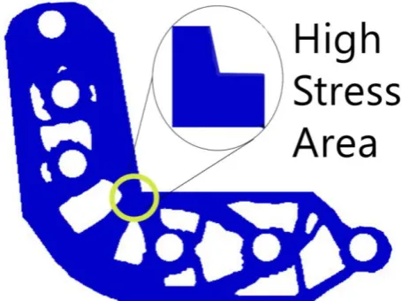
migration, oxide film irregularities, etc.) in the implant metal itself induced by body fluids and high stress variation of the implant. Shape optimization is chosen to by fatigue based. So, it can focus only on the high-stress areas effectively and fast such that the fatigue curve is a convex curve, making the optimization process is smooth and straightforward.
VIII. CASE STUDY
[image:5.595.317.545.113.283.2]The case in hand is for patient of angle fracture of the mandible. The fixing plate has been introduced to proximate the fracture ends to secure the mandible fragments along the fracture line. Securing the fragments in a secure and optimal attachment is to ease the bone building by osteoblast. The designing process has been performed by two cascade models. The two cascade models been tested. First one is topology optimization followed by fatigue-based topology optimization. The second model is shape optimization followed by fatigue-based topology optimization. Fig. 2 is the designed plate using topology optimization. Topology optimization computing been done with parallel processing.
[image:5.595.47.282.325.499.2]Fig. 1. Case Study of fracture mandible
Fig. 2. Fixing plate
IX. RESULTS
Performing the first cascade model, i.e. Stress based topology optimization then transfer the results to fatigue
based topology optimization has been shown in Fig. 3 and Fig. 5. The objective function history has been shown in Fig. 4 and Fig. 6
[image:5.595.315.553.325.514.2]Fig. 3 First stage of first cascade model: Topology optimization
[image:5.595.51.266.542.719.2]Fig. 4. Objective function history of topology optimization
[image:5.595.322.551.557.738.2]Fig. 6. Objective function history of fatigue-based topology optimization
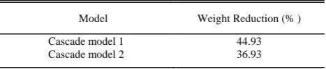
[image:6.595.306.540.184.234.2]Performing stress-based shape optimization then transfer the results to fatigue based topology optimization has been shown in Fig. 7 and Fig. 8. Fatigue life of the original plate which (1.4e7) has been improved in each optimization stage (Table 1). Table II showed the weight reduction for the optimization process.
Fig. 7 First stage of second cascade model: Shape optimization
Fig. 8. Second stage of second cascade model: fatigue based optimization TABLEII
WEIGHT REDUCTIONRESULTS
Model Weight Reduction (% ) Cascade model 1 44.93 Cascade model 2 36.93
X. CONCLUSIONS
Fist cascade model (Stress based topology-Fatigue based optimization) reduced the weight significantly, yet the fatigue life of the cascade model (Stress based shape-fatigue based optimization) doubled the fatigue life. Second cascade model gave the better results in term of achieving the major objective which is fatigue life reduction.
REFERENCES
[1] S. Kocanda, “Fatigue failure of metals,” 1978.
[2] A. Head, “XCVIII. The growth of fatigue cracks,” The London, Edinburgh, and Dublin Philosophical Magazine and Journal of
Science, vol. 44, no. 356, pp. 925-938, 1953.
[3] M. P. Bendsoe, and O. Sigmund, Topology optimization: theory,
methods, and applications: Springer Science & Business Media,
2013.
[4] J. Bannantine, “Fundamentals of metal fatigue analysis,”
Prentice Hall, 1990, pp. 273, 1990.
[5] K. Walker, "The effect of stress ratio during crack propagation and fatigue for 2024-T3 and 7075-T6 aluminum," Effects of
environment and complex load history on fatigue life: ASTM
International, 1970.
[6] J. Collipriest Jr, “An experimentalist's view of the surface flaw problem,” Paper from" The Surface Crack- Physical Problems
and Computational Solutions", ASME, New York. 1972, 43-61.,
1972.
[7] R. C. Juvinall, Engineering considerations of stress, strain, and
strength: McGraw-Hill New York, 1967.
[8] K.-T. Cheng, and N. Olhoff, “An investigation concerning optimal design of solid elastic plates,” International Journal of Solids and Structures, vol. 17, no. 3, pp. 305-323, 1981. [9] G. I. Rozvany, Topology optimization in structural mechanics:
Springer, 2014.
[10] G. Bohm, Pressure vessels and piping: design and analysis; a
decade of progress: American Society of Mechanical Engineers,
1972.
[11] M. Y. Wang, X. Wang, and D. Guo, “A level set method for structural topology optimization,” Computer methods in applied
mechanics and engineering, vol. 192, no. 1-2, pp. 227-246,
2003.
[12] M. A. Ali, “Design Offshore Spherical Tank Support using Shape Optimization,” in Proceedings of the 6th IIAE International Conference on Intelligent Systems and Image Processing 2018, Japan, 2018, pp. 6.
[13] C. Groth, A. Chiappa, and M. Biancolini, “Shape optimization using structural adjoint and RBF mesh morphing,” Procedia Structural Integrity, vol. 8, pp. 379-389, 2018.
[14] P. Penzler, M. Rumpf, and B. Wirth, “A phase-field model for compliance shape optimization in nonlinear elasticity,” ESAIM:
TABLEI FATIGUE LIFE RESULTS
Model First Stage
(Cycles)
Second Stage (Cycles) Cascade model 1 2 x 10⁸ 3.4 x 10⁹
[image:6.595.58.555.400.790.2] [image:6.595.60.269.405.574.2]Control, Optimisation and Calculus of Variations, vol. 18, no. 1, pp. 229-258, 2012.
[15] T. H. Nguyen, G. H. Paulino, J. Song, and C. H. Le, “Improving multiresolution topology optimization via multiple discretizations,” International Journal for Numerical Methods in Engineering, vol. 92, no. 6, pp. 507-530, 2012.
[16] A. Takezawa, S. Nishiwaki, and M. Kitamura, “Shape and topology optimization based on the phase field method and sensitivity analysis,” Journal of Computational Physics, vol. 229, no. 7, pp. 2697-2718, 2010.
[17] C. H. Villanueva, and K. Maute, “Density and level set-XFEM schemes for topology optimization of 3-D structures,”
Computational Mechanics, vol. 54, no. 1, pp. 133-150, 2014.
[18] A. T. Musaddiq Al Ali, Mitsuru Kitamura, "Comparative Study of Stress Minimization Using Topology Optimization and Morphing Based Shape Optimization."
[19] M. Biancolini, C. Groth, E. Costa, and F. Lagasco, "A mesh morphing based technique to efficiently perform FSI analyses for aeroelastic design applications." pp. 9-12.
[20] I. A. Sigal, M. R. Hardisty, and C. M. Whyne, “Mesh-morphing algorithms for specimen-specific finite element modeling,”
Journal of biomechanics, vol. 41, no. 7, pp. 1381-1389, 2008.
[21] G. Rozvany, “Topology optimization in structural mechanics,”
Structural and Multidisciplinary Optimization, vol. 21, no. 2, pp. 89-89, 2001.
[22] H. L. Cox, The Design of Structures of Least Weight: International Series of Monographs in Aeronautics and
Astronautics: Solid and Structural Mechanics: Elsevier, 2014.
[23] J. C. Maxwell, The Scientific Papers of James Clerk Maxwell: University Press, 1890.
[24] A. G. M. Michell, “LVIII. The limits of economy of material in frame-structures,” The London, Edinburgh, and Dublin
Philosophical Magazine and Journal of Science, vol. 8, no. 47,
pp. 589-597, 1904.
[25] G. Hegemier, and W. Prager, “On michell trusses,” International Journal of Mechanical Sciences, vol. 11, no. 2, pp. 209-215, 1969.
[26] D. C. Drucker, and R. Shield, Design for Minimum Weight, BROWN UNIV PROVIDENCE RI, 1956.
[27] A. Chan, The design of Michell optimum structures, College of Aeronautics Cranfield, 1960.
[28] D. L. Bartel, Optimum design of spatial structures, IOWA UNIV IOWA CITY DEPT OF MECHANICS AND HYDRAULICS, 1969.
[29] D. Charrett, and G. Rozvany, “Extensions of the Prager-Shield theory of optimal plastic design,” International Journal of
Non-Linear Mechanics, vol. 7, no. 1, pp. 51-64, 1972.
[30] G. Rozvany, and W. Prager, “Optimal design of partially discretized grillages,” Journal of the Mechanics and Physics of Solids, vol. 24, no. 2-3, pp. 125-136, 1976.
[31] M. Rossow, and J. Taylor, “A finite element method for the optimal design of variable thickness sheets,” Aiaa Journal, vol. 11, no. 11, pp. 1566-1569, 1973.
[32] M. P. Bendsøe, and N. Kikuchi, “Generating optimal topologies in structural design using a homogenization method,” Computer methods in applied mechanics and engineering, vol. 71, no. 2, pp. 197-224, 1988.
[33] M. P. Bendsøe, “Optimal shape design as a material distribution problem,” Structural and multidisciplinary optimization, vol. 1, no. 4, pp. 193-202, 1989.
[34] R. D. Cook, “Finite element modeling for stress analysis/Robert D. Cook,” 1994.
[35] P. Duysinx, and M. P. Bendsøe, “Topology optimization of continuum structures with local stress constraints,” International
journal for numerical methods in engineering, vol. 43, no. 8, pp.
1453-1478, 1998.
[36] C. Le, J. Norato, T. Bruns, C. Ha, and D. Tortorelli, “Stress-based topology optimization for continua,” Structural and Multidisciplinary Optimization, vol. 41, no. 4, pp. 605-620, 2010.
[37] E. Holmberg, B. Torstenfelt, and A. Klarbring, “Stress constrained topology optimization,” Structural and
Multidisciplinary Optimization, vol. 48, no. 1, pp. 33-47, 2013.
[38] W. P. Ziemer, Weakly differentiable functions: Sobolev spaces
and functions of bounded variation: Springer Science &
Business Media, 2012.
[39] A. Verbart, “Topology Optimization with Stress Constraints,” TU Delft, Delft University of Technology, 2015.
[40] R. Huiskes, H. Weinans, and B. Van Rietbergen, “The relationship between stress shielding and bone resorption around total hip stems and the effects of flexible materials,” Clinical
orthopaedics and related research, pp. 124-134, 1992.
[41] F. Dirksen, M. Anselmann, T. I. Zohdi, and R. Lammering, “Incorporation of flexural hinge fatigue-life cycle criteria into the topological design of compliant small-scale devices,”
Precision Engineering, vol. 37, no. 3, pp. 531-541, 2013.
[42] S. H. Jeong, D.-H. Choi, and G. H. Yoon, “Fatigue and static failure considerations using a topology optimization method,”
Applied Mathematical Modelling, vol. 39, no. 3-4, pp. 1137-1162, 2015.
[43] Y. Murakami, The Rainflow Method in Fatigue: The Tatsuo
Endo Memorial Volume: Butterworth-Heinemann, 2013.
[44] K. Sieradzki, and R. Newman, “Stress-corrosion cracking,”
Journal of physics and chemistry of solids, vol. 48, no. 11, pp. 1101-1113, 1987.
[45] J. Scully, “Kinetic features of stress-corrosion cracking,”
Corrosion Science, vol. 7, no. 4, pp. 197-207, 1967.