warwick.ac.uk/lib-publications
Original citation:Moztarzadeh, Hadi, Hughes, Darren J., Seth, Sampan, Keating, Elspeth, Kirachi, Ercihan , Gibbons, Gregory John and Dashwood, R. J. (2015) Evolution of residual stresses in linear deposition wire-based cladding of Ti-6Al-4V. In: 8th International Conference on Mechanical Stress Evaluation by Neutron & Synchrotron Radiation MACASENS 2015, Grenoble, France, 30 Sep -2 Oct 2015. Published in: Materials Science Forum (In Press)
Permanent WRAP URL:
http://wrap.warwick.ac.uk/78892
Copyright and reuse:
The Warwick Research Archive Portal (WRAP) makes this work by researchers of the University of Warwick available open access under the following conditions. Copyright © and all moral rights to the version of the paper presented here belong to the individual author(s) and/or other copyright owners. To the extent reasonable and practicable the material made available in WRAP has been checked for eligibility before being made available.
Copies of full items can be used for personal research or study, educational, or not-for-profit purposes without prior permission or charge. Provided that the authors, title and full
bibliographic details are credited, a hyperlink and/or URL is given for the original metadata page and the content is not changed in any way.
Publisher’s statement: http://www.ttp.net/
A note on versions:
The version presented here may differ from the published version or, version of record, if you wish to cite this item you are advised to consult the publisher’s version. Please see the ‘permanent WRAP URL’ above for details on accessing the published version and note that access may require a subscription.
Evolution of residual stresses in linear deposition wire-based
cladding of Ti-6Al-4V
Hadi Moztarzadeh
1, a *, Darren J. Hughes
1,
Sampan Seth
1, Elspeth
Keating
1, Ercihan Kiraci
1, Gregory J. Gibbons
1, Richard J. Dashwood
1WMG, University of Warwick, Coventry, CV4 7AL, UK
Keywords: Plasma Transferred Arc Cladding, Additive Manufacturing, Titanium alloy, Residual stress, Neutron Diffraction
Abstract. Neutron diffraction and curvature measurements were conducted to investigate the residual stresses associated with Plasma Transferred Arc Cladding (PTA) of Ti-6Al-4V on a substrate of the same material. The wire-feed PTA coupled with 3-axis CNC machine was used as an Additive Manufacturing (AM) technique to build parts. A combination of the process parameters was chosen to investigate their effects on residual stress evolution. Neutron Diffraction (ND) measurements of residual strains were performed on the SALSA instrument at the Institut Laue-Langevin (ILL), Grenoble, France. Longitudinal stresses were also inferred by using a Coordinate Measurement Machine (CMM) and Euler-Bernoulli beam theorem. Furthermore, Optical Microscopy (OM) of the cross section of the parts was used to analyse the microstructural evolution. The results show the effect of shorter and longer ‘dwell time’ between layers on the evolution of residual stresses.
Introduction
Titanium alloys have become a material of great interest for different industrial applications due to their excellent corrosion resistance, low density, excellent high temperature mechanical properties and biocompatibility [1, 2]. Manufacturing components in a layer-by-layer fashion offers a high geometrical flexibility and great potential for time and cost savings in comparison to conventional manufacturing technologies [3]. The Additive Manufacturing (AM) of small and medium-sized Ti–6Al–4V parts represents an interesting business case for a number of industrial applications.
The Plasma Transferred Arc Cladding (PTA) coupled with 3-axis CNC platform has recently been used as an AM technique. Linear beads of the material are deposited by using PTA. A range of metallic materials have been used in this technique, such as titanium alloys, Inconel and high chromium steel. Understanding the effects of the manufacturing process on the performance of the final part is the key when highly reliable final product is required [1-3].
Residual stresses are important in weld beads as they induce high, typically tensile stress are produced combined with unfavourable microstructure changes and flaws [4]. Diffraction techniques and in particular neutron diffraction is a viable option to measure residual stresses in weld depositions [5].
Experimental methods
Manufacturing of the parts. Process parameters for a powder-based PTA welding are described in the literature [7]. For the wire-based PTA used in this study, the process parameters are summarised in Table 1.
Table 1 – Process parameters for PTA as an AM process
Parameter Value Range Unit
Plasma Gas Flow Rate (PGFR) 0.5 l/min
Wire Feed Rate (WFR) 1 m/min
Traverse Speed/Weld Speed 50 mm/min
Energy Density ~135 MJ/m2
Deposition Strategy Linear -
Dwell Time 60-180 sec
The energy density in Table 1 has been calculated from both the traverse speed (weld speed) and current. Since the PTA cladding has been used as an AM technique, the phenomena between layers should be considered as a process parameter. This is considered to be the ‘dwell time’ between layers. This would give an indication of the temperature of the layer before depositing the next one. Also the AM building strategy should be taken into account as another process parameter for the AM process. In the case of PTA we define the building strategy to be the deposition direction. A linear deposition strategy is considered for this study although further is under way looking at the effect of path type (e.g. zig-zag). From Table 1, sample 1 has a dwell time of 60 sec and sample 2 has a dwell time of 180 sec.
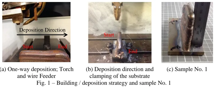
The fixture of the substrate and deposition direction are shown in Fig 1. One-way deposition path was chosen due to the position of wire-feeder, electrode and torch on the PTA [8].
(a) One-way deposition; Torch and wire Feeder
(b) Deposition direction and clamping of the substrate
(c) Sample No. 1
Fig. 1 – Building / deposition strategy and sample No. 1
[image:3.595.90.520.436.611.2]Material Model and Microstructural Analysis. Nominal material properties of the wire and substrate are given in Table 2. An optical microscope was used to study the microstructure of the cross section of the deposited beads. This facilitates an understanding of the phases on different regions of the samples cross section.
Table 2 – Nominal material/mechanical properties of the Ti-6Al-4V wire
Property Value Unit
Tensile Strength, Ultimate 950 MPa
Tensile Strength, Yield 880 MPa
Modulus of Elasticity 113.8 GPa
Poisson's Ratio 0.342 -
Deposition Direction
Start End
Start
A two layer sample was built using a ‘linear’ deposition strategy. The direction of cladding and process parameters was the same as the actual parts for residual stress measurement to replicate the process. Micrographs were obtained by an optical microscope using polarised light to analyse the microstructure.
Curvature Measurement. In the work presented here, two methods were used to measure the residual stress in the samples: curvature measurement and neutron diffraction [6].
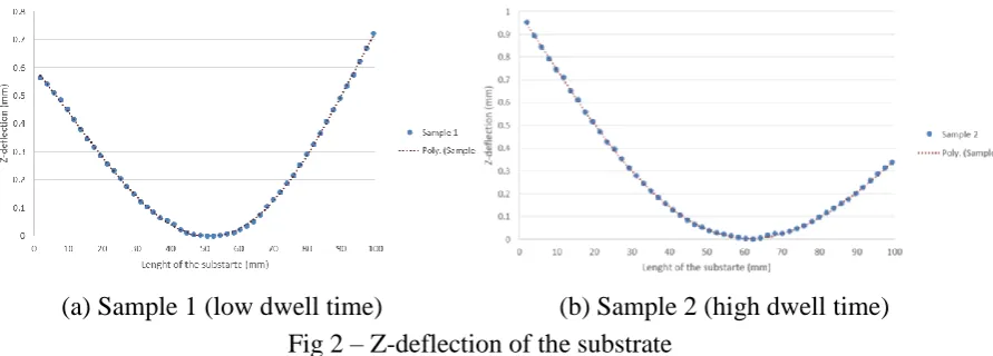
According to curvature measurement technique, the resulting changes in curvature during deposition make it possible to calculate the corresponding variations in stress as a function of the geometry of the part and material property. The result for the deflection of the substrate in samples 1 and 2 are shown in Fig 2. A polynomial curve fitting process was conducted to derive the curvature equation. Therefore, the Euler-Bernoulli beam theory could be applied to calculate the internal bending moment as a function of the length of the bead (substrate) and then internal bending stresses can ben determined.
[image:4.595.82.528.292.452.2](a) Sample 1 (low dwell time) (b) Sample 2 (high dwell time) Fig 2 – Z-deflection of the substrate
Neutron Diffraction. The SALSA instrument at the Institut Laue-Langevin (ILL) was used to measure residual strains in the AM parts. Measurements were conducted along a longitudinal path at the middle of the height of the parts 20 mm below the reference surface (top bead). Seven points were chosen on this line starting from the lateral surface towards the middle of the sample. The distance between each scanned point was kept to be 5 mm. Thus, the scanned points started from 0 mm and ended at 30 mm with respect to the lateral surface on the start-side of the beads as shown in Fig 3.
Fig 3 – Schematic of the part and neutron diffraction measurement points
𝑛𝜆 = 2𝑑𝑠𝑖𝑛𝜃 (1)
Where λ is the wavelength, n is an integer, d is the spacing between the planes of the atomic lattice and 2θ is the angle between the incident and scattering beams. To calculate the principal strains a fixed wavelength and known θ0 (stress-free condition) is assumed. Then ‘d’ spacing is scanned in all three principal directions (Y: longitudinal, Z: Transverse and X: out of plane). The principal strains are calculated using Eq. 2 [5].
𝜀 =𝑑−𝑑0
𝑑0 = − cot 𝜃. (𝜃 − 𝜃0) (2)
Results and Discussion
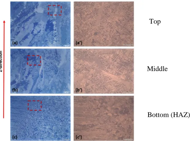
[image:5.595.177.495.275.512.2]Microstructural analysis reveals micrographs as shown in Fig 4. The images obtained from different regions to look at the differences between bottom, middle and top of the layers.
Fig 4 – optical micrographs of the cross section of two layers of Ti-6Al-4V weld sample showing (a and a’) top, (b and b’) middle and (c and c’) bottom of the layers (HAZ)
Fig 4 (a)-(c) indicates formation of columnar β grains which shows considerable increase in grain size from the bottom to the top edge of the deposition. This has been attributed to the rate of solidification during the process, where precipitation of directionally oriented Body Centred Cubic (BCC) β grains has been observed. Fig 1(a’) and (b’) illustrates a higher magnification optical micrographs of the selected regions from the top and middle layers. ‘Fine’ lamella type microstructure can be observed. This type of microstructure (widmanstatten type or Basket-weave type) has been reported by previous researchers as a results of precipitation of α phase within the β grains due to rapid cooling cycles during the process [9]. A ‘coarser’ microstructure was seen towards the bottom of the layers [10].
Residual stresses calculated by bending (curvature measurement) and neutron diffraction for the two samples are plotted in Fig 5.
Top
Middle
(a) Sample 1 (lower dwell time)
[image:6.595.121.478.67.492.2](b) Sample 2 (higher dwell time)
Fig 5 – Longitudinal residual stress measurement: bending stress by Curvature Measurement (CM) and actual stress by Neutron Diffraction (ND)
Based on the distribution of the stress within the part, the longitudinal stress starts with a compressive stress at the lateral surface and then increases towards the centre of the part. Almost at the middle of the part a tensile stress can be observed by both bending measurement and neutron diffraction. Neutron diffraction results give a full image of the stress state at each point while the bending stress only represents the longitudinal stress at each point. However, comparing the results from neutron diffraction and curvature measurement, the majority of the stress magnitude can be assumed to be bending stress. This can be justified by the clamping strategy as well as geometrical condition of the deposition. Both of these two parameters replicated a beam-model scenario and stress induced in the same manner. The full stress state from neutron diffraction will be repeated in detail elsewhere.
Conclusion
The wire-feed PTA coupled with a 3-axis CNC was used as an AM technique to build parts. This offers an exciting method for metal-based layer by layer manufacturing process. Neutron diffraction and curvature measurements were used to study the residual stresses associated with PTA of Ti-6Al-4V. Two samples with two different ‘dwell time’ were built to investigate the effect of longer and shorter cooling process between layers on the evolution of residual stresses. It was shown that increasing dwell time could reduce the level of residual stresses within the part. Residual stresses started with a compression at the lateral surface of the part towards a tension at the middle of the part. A correlation occurs between the results from Neutron Diffraction and curvature measurement which confirms that the majority of the residual stress could be interpreted as bending stress.
References
[1] M. Roggensack, M. H. Walter, and K. W. Bsning, “Studies on laser- and plasma-welded titanium,” vol. 6507, no. 1983, pp. 104–107, 1993.
[2] E. Akman, a. Demir, T. Canel, and T. Sinmazçelik, “Laser welding of Ti6Al4V titanium alloys,”
J. Mater. Process. Technol., vol. 209, no. 8, pp. 3705–3713, 2009.
[3] B. Baufeld, E. Brandl, and O. Van Der Biest, “Wire based additive layer manufacturing: Comparison of microstructure and mechanical properties of Ti-6Al-4V components fabricated by laser-beam deposition and shaped metal deposition,” J. Mater. Process. Technol., vol. 211, no. 6, pp. 1146–1158, 2011.
[4] D. W. Brown, T. M. Holden, B. Clausen, M. B. Prime, T. a. Sisneros, H. Swenson, and J. Vaja, “Critical comparison of two independent measurements of residual stress in an electron-beam welded uranium cylinder: Neutron diffraction and the contour method,” Acta Mater., vol. 59, no. 3, pp. 864–873, 2011.
[5] C. Acevedo, a. Evans, and a. Nussbaumer, “Neutron diffraction investigations on residual stresses contributing to the fatigue crack growth in ferritic steel tubular bridges,” Int. J. Press. Vessel. Pip., vol. 95, pp. 31–38, 2012.
[6] P. J. Withers and H. K. D. Bhadeshia, “Residual stress Part 1 – Measurement techniques,” Mater. Sci. Technol., vol. 17, no. 4, pp. 355–365, 2001.
[7] J. Wilden, J. P. Bergmann, and H. Frank, “Plasma Transferred Arc Welding—Modeling and Experimental Optimization,” J. Therm. Spray Technol., vol. 15, no. 4, pp. 779–784, 2006. [8] L. Parimi, D. Clark, and M. M. Attallah, “Microstructural and texture development in direct
laser fabricated IN718,” Mater. Charact., vol. 89, pp. 102–111, 2014.
[9] N. Poondla, T. S. Srivatsan, A. Patnaik, and M. Petraroli, “A study of the microstructure and hardness of two titanium alloys: Commercially pure and Ti–6Al–4V,” J. Alloys Compd., vol. 486, no. 1–2, pp. 162–167, 2009.