Original citation:
Clark, Leon, Shirinzadeh, Bijan, Tian, Yanling and Zhong, Yongmin. (2014) The bounds on tracking performance utilising a laser-based linear and angular sensing and
measurement methodology for micro/nano manipulation. Measurement Science and Technology, 25 (12). 125005.
Permanent WRAP url:
http://wrap.warwick.ac.uk/76390
Copyright and reuse:
The Warwick Research Archive Portal (WRAP) makes this work by researchers of the University of Warwick available open access under the following conditions. Copyright © and all moral rights to the version of the paper presented here belong to the individual author(s) and/or other copyright owners. To the extent reasonable and practicable the material made available in WRAP has been checked for eligibility before being made available.
Copies of full items can be used for personal research or study, educational, or not-for profit purposes without prior permission or charge. Provided that the authors, title and full bibliographic details are credited, a hyperlink and/or URL is given for the original metadata page and the content is not changed in any way.
Publisher’s statement:
“The final publication is available at Springer via http://dx.doi.org/10.1007/s00170-015-6881-0 ."
A note on versions:
The version presented here may differ from the published version or, version of record, if you wish to cite this item you are advised to consult the publisher’s version. Please see the ‘permanent WRAP url’ above for details on accessing the published version and note that access may require a subscription.
Thermal Simulation Modeling of a Hydrostatic
Machine Feed Platform
Teng Liu1, Weiguo Gao1, 2, Yanling Tian1, 2, Ken Mao2, Gaoxing Pan1, 3, Dawei Zhang1
1
Key Laboratory of Mechanism Theory and Equipment Design of Ministry of Education, Tianjin
University, Tianjin 300072, China
2
School of Engineering, University of Warwick, Coventry, CV4 7AL, UK
3
Tianjin No.2 Machine Tool Co., Ltd., Tianjin 300409, China
Abstract: Hydrostatic guideways are widely applied into precision and ultra-precision machine tools. Meanwhile, the oil film heat transfer causes thermal disturbance to the machine accuracy. Therefore, it is necessary to study the mechanism of the oil film heat transfer and the heat transfer reducing method to improve the machine accuracy. This paper describes a comprehensive thermal FE simulation modeling method for the hydrostatic machine feed platform to study methods of reducing machine thermal errors. First of all, the generating heat power of viscous hydraulic oil flowing between parallel planes is calculated based on Bernoulli equation. This calculation is then employed for the simulation load calculations for the closed hydrostatic guideways, which is adopted by the hydrostatic machine feed platform. Especially, in these load calculations, the changing of oil film thickness (resulted from external loads) and the changing of oil dynamic viscosity (influenced by its temperature) are taken into account. Based on these loads, thermal FE simulation modeling of the hydrostatic machine feed platform is completed to predict and analyze its thermal characteristics. The reliability of this simulation modeling method is verified by experiments. The studies demonstrate that: the hydrostatic machine thermal error degree is determined by the oil film heat transfer scale, and this scale is mainly influenced by the relative oil supply temperature to ambient temperature (quantitative comparison of oil supply temperature and ambient temperature). Furthermore, the reduction of the absolute value of this relative oil supply temperature can reduce the oil film heat transfer scale, and improve the machine accuracy.
Keywords: Thermal simulation modeling, Hydrostatic machine feed platform, Closed hydrostatic guideways, FE, Thermal errors
Nomenclature
W: Width of parallel planes (m)
L: Length of parallel planes (m)
h: Clearance between parallel planes (m)
Pin /Pou: Pressures of viscous hydraulic oil at input / output sides of parallel planes (Pa) P: Pressure of flow viscous hydraulic oil (Pa)
u: Velocity of flow viscous hydraulic oil (m/s)
t: Moment (s)
g: Acceleration due to gravity (m/s2)
m: Mass of slide (kg)
ρ: Density of hydraulic oil (kg/m3)
hw: Friction power in 1 N gravity of oil film (m)
ηt: Average dynamic viscosity of hydraulic oil at a moment t (Pa·s)
η0(T0) : Dynamic viscosity of hydraulic oil when its temperature is T0 (Pa·s) PS: Supply pressure of hydraulic oil (Pa)
TS: Supply temperature of hydraulic oil (℃) Qt: Volume flow rate of hydraulic oil (m3/s)
Qt_1 /Qt_2: Volume flow rate of oil films of pad 1/2 (m3/s)
QG_1 /QG_2: Volume flow rate of oil film on gap restrictor of pad 1/2 (m3/s) QL_1 /QL_2: Volume flow rate of oil film on land of pad 1/2 (m3/s)
Ht: Heat generated by friction power of oil films (J/s)
Ht_1 /Ht_2: Heat generated by friction power of oil films of pad 1/2 (J/s)
Ht_up /Ht_low /Ht_hor: Heat generated by friction power of oil films of upper/lower/horizontal pad (J/s) HG_1 /HG_2: Heat generated by friction power of oil film on gap restrictor of pad 1/2 (J/s)
HL_1 /HL_2: Heat generated by friction power of oil film on land of pad 1/2 (J/s) Ae: Effective bearing area of hydrostatic pad (m2)
E: External load (N)
EV /EH: External load on vertical/horizontal direction (N) ε (1>ε≥0): Relative displacement of oil film
εV /εH (1>εV≥0, 1>εH≥0): Relative displacement of vertical/ horizontal oil films β: Design pressure ratio of hydrostatic pad
β1 /β2: Pressure ratio of hydrostatic pad 1/2
F1(=PR_1Ae) /F2(=PR_2Ae): Reaction force from pad 1/2 (N) LG /WG: Length/ Width of gap restrictor (m)
LL: Radial scale of land (m)
WL: Average circumferential scale of land (m)
Mt_1 /Mt_2: Mass flow rate of oil films of pad 1/2 (kg/s)
Mt_up /Mt_low /Mt_hor: Mass flow rate of oil films of upper/lower/horizontal pad (kg/s) J1 /J2: Stiffness of oil films of pad 1/2 (N/m)
Jup /Jlow /Jhor: Stiffness of oil films of upper/lower/horizontal pad (N/m)
γ: V-T index coefficient
T: Temperature of hydraulic oil (℃)
Tout(t): Output oil temperature of hydrostatic pad at moment t (℃)
Tout_up(t) /Tout_low(t) /Tout_hor(t): Output oil temperature of upper /lower /horizontal hydrostatic pad at a
moment t (℃)
ρM: Density of metal material of machine (kg/m3)
kM: Thermal conductivity of metal material of machine (w/(m·K)) cM: Specific heat of metal material of machine(J/(kg·K))
JM: Stiffness of metal material of machine (N/m) μ: Poisson's ratio of metal material of machine
α: Linear expansion coefficient of metal material of machine
c: Specific heat of hydraulic oil (J/(kg·K))
TPA/ TPB/ TPC/ TPD Measured temperature of Position A-D (℃) Tout Output temperature of hydraulic oil (℃)
T1 /T2 /T3: Temperature gradient from oil films to environment in Condition 1/2/3 (℃) TA: Ambient temperature (℃)
tT /tS: Total time/Substep time length in transient FE simulation (min)
△X/ △Y/ △Z: Machine feed errors on X/Y/Z direction (X: positioning error; Y/Z: straightness error) δX/ δY/ δZ: Machine feed angle errors around X/Y/Z direction
d: Distance of the 2 parallel lines in Fig.16
1 Introduction
Past decades have witnessed an increasingly widespread application of hydrostatic guideways or bearings into various kinds of high-precision and ultra-precision machine tools, owing to their special advantages [1]. These advantages include zero starting friction, low viscous running friction, high load-carrying capacity, high stiffness, high positioning accuracy and so on [2]. Nevertheless, when the hydrostatic machine is working, the convective heat transfer exists between the oil films and the surface of machine metal material, and causes machine thermal errors. Therefore, the thermal simulation modeling investigation and the heat transfer reduction of the hydrostatic guideways or bearings can contribute to the accuracy improvement of the hydrostatic machine tools.
The thermal modeling method is the critical basis for the research on thermal characteristics and regulations of the hydrostatic guideways or bearings. A variety of researching efforts about this topic were based on experimental modeling methods. Yang et al [3] studied the thermal effects in liquid oxygen hydrostatic journal bearings experimentally. Sharma et al [4-5] measured and summarized the influence of oil temperature rise on the symmetric and asymmetric slot-entry hybrid journal bearing, as well as the influence of oil temperature rise and bush deformation on static and dynamic performances of hole-entry hybrid journal bearing. Park et al [6] investigated the relationship between oil temperature and positioning error of hydrostatic guideways by experimental methods. Kumar et al
[7]
characteristics of hydrostatic guideways and bearings. Kapur et al [9] investigated the simultaneous inertia and temperature effects on the model of parallel stepped hydrostatic thrust bearing, and obtained the expressions for pressure profile and load capacity under the conditions of the adiabatic flow. Sun et al [10] studied the steady temperature field of double-rows and narrow cavity hydrostatic and hydrodynamic hybrid bearings based on the adiabatic assumption and THD analysis. Zhang et al
[11]
adopted the finite difference method to overcome the simultaneous general Reynolds equation, energy equation and bearing thermal conductivity equation, analyzed theoretically the temperature field of the shallow recess step hydrostatic and hydrodynamic bearing. Zhang et al [12] calculated the correlation between the pressure, temperature of hydraulic oil and its turbulence, density, viscosity about the hydrostatic and hydrodynamic hybrid bearing with a capillary restrictor and 4 recesses. Fu et al [13] established the 3-dimensional temperature field model of hydrodynamic bearing, with the heat flux continuity condition, by the simultaneous solution of the generalized Reynolds equation, 3 dimensional energy equations, 3 dimensional heat transfer equation and force equilibrium equation. Chen et al [14] studied the thermal deformation effect of a hydrostatic spindle onto its oil films thickness, stiffness, load capacity and machine accuracy, by a thermo-mechanical FE model. Jiang et al [15] analyzed thermal deformation influence to the machine accuracy of high-speed moving guide under different conditions by FE simulation method. Wang et al [16] estimated the power consumption of hydrostatic guideways in working process, and analyze the influence from its thermal deformation to machine accuracy by FE simulation method. Su et al [17] established a hydrostatic spindle system model by FVEM, and then studied the variation of its predicted thermal behaviors. These studies tried to establish mechanism models to analyze the thermal characteristics of hydrostatic guideways or bearings. But in these models, the hydrostatic heat transfer was always ignored or simplified to be constant values, which reduced their modeling accuracy. The heat transfer variation of hydrostatic guideways or bearings and its association with working conditions (such as oil supply temperature and ambient temperature) can hardly be studied based on them.
to be related to the relative oil supply temperature to ambient temperature, and this heat transfer scale leads to the machine thermal error. The structure of this paper is arranged as follows: Section 2 introduces the necessary theory preparations of the thermal simulation modeling procedure for the hydrostatic machine feed platform. The discussed heat modeling of viscous hydraulic oil flowing between parallel planes is applied onto the required simulation load calculations. Then based on these loads, in Section 3, thermal FE simulation modeling of hydrostatic machine feed platform is realized under various working conditions. In Section 4, the reliability of this FE simulation modeling method of hydrostatic machine feed platform is verified by experimental method. Furthermore, based on the simulation modeling results, Section 5 analyzes systemically the association between thermal errors of hydrostatic machine feed platform and its working condition (oil supply temperature and ambient temperature). Eventually, conclusions of the paper are summarized in Section 6.
2 Theory analyses for thermal simulation modeling of hydrostatic machine feed platform
This section discusses the theory preparations for the thermal FE simulation modeling method of the hydrostatic machine feed platform. Fig.1 depicts the logical relationships of these theory preparations: The necessary calculated loads for the thermal simulation modeling of hydrostatic machine feed platform includes mass flow rate, friction power and stiffness of oil films. These calculations consider the changing of oil film thickness (resulted from external loads) and the changing of oil dynamic viscosity (influenced by its supply temperature), and they are guided by the heat modeling of viscous hydraulic oil flowing between parallel planes. The thermal FE simulation modeling of hydrostatic machine feed platform will be completed based on these calculated loads. The calculation methods are deduced as follows.
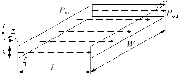
of friction power generated by viscous hydraulic oil flowing between parallel planes. This modeling is described in Fig. 2: The viscous hydraulic oil has a laminar flow on X direction between fixed parallel planes 1 and 2. Parallel planes have the same width W, same length L,and a clearance h (L»h, W»h). The pressure values of the flowing viscous hydraulic oil at input and output sides of parallel planes are
Pin and Pou respectively (Pin›Pou). L»h and W»h mean that the flowing viscous hydraulic oil has the
approximately uniform temperature and pressure distributions on Y and Z directions. So, with the potential energy of flowing viscous hydraulic oil being ignored, the Bernoulli equation for viscous liquid at a moment t is:
2
2 in
in
w
d d
( ) ( )
d d
2 2
P u
P L u L
P u x x
h
g g g g
(1)
The laminar flow meansd / du x0, which presents the uniform flow velocity of viscous hydraulic oil on X direction. So equation (1) can be simplified by d / du x0 as follows:
w
d
0 d
L P h g x
(2)
Besides, there is a linear pressure decline of the flow viscosity hydraulic oil on X direction, which means:
ou in
d d
P P P
x L
(3)
w in ou
1
( )
h P P
g
(4)
The volume flow rate Qt at the moment t is [18]:
3
in ou
( ) 12
t t Wh
Q P P L
(5)
Then the heat generated by friction power of the flowing viscous hydraulic oil at the moment t can be expressed as:
w
t t
H h
gQ (6)
Substituting equations (4) and (5) into equation (6), the friction power Ht of the flowing viscous
hydraulic oil at the moment t is:
3
2 in ou
( ) 12
t t
Wh
H P P L
(7)
The conclusions of this subsection are preparations and guidance for simulation load calculations of closed hydrostatic guideways with gap restrictors.
2.2 Simulation load calculations of closed hydrostatic guideways with gap restrictors considering
the variation of oil film thickness
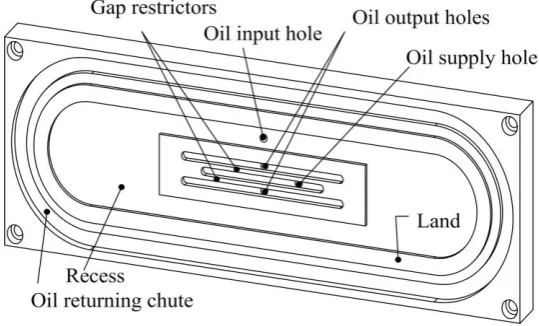
The structure of the single pad of closed hydrostatic guideways with gap restrictors is shown in the axonometric drawing Fig. 3(a). And Fig. 3(b) is an orthography drawing of gap restrictors and land, especially the average circumferential length WL of the land is shown as a dash and dot line and has a
middle position between the inner and outer edges of land. Meanwhile, the effective bearing area Ae of
the hydrostatic pad is the area surrounded by the dash and dot line in Fig. 3(b).
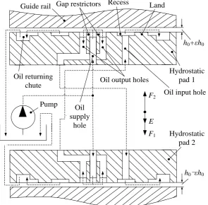
The operational principle of the closed hydrostatic guideways with gap restrictors is shown in Fig.4. This figure illustrates the hydrostatic pad 1(2) to be a view of cross section A-A of Fig.3 (b): When the pump is switched on, the pressurized hydraulic oil is conveyed from oil supply hole into hydrostatic pad 1(2). It flows into clearances between bilateral gap restrictors and guide rail to form oil films in them, and be directed by oil output holes into internal pipelines, then be collected by oil input hole of the opposite pad 2(1) into its recess. Finally, it flows into the clearance between land and guide rail to form the oil film, and goes into the oil returning chute. If an external load E is exerted on the closed hydrostatic guideways with gap restrictors, the oil film thickness values of hydrostatic pads 1 and 2 will be h0+εh0 and h0-εh0, respectively.
The thickness scale of oil films is far less than its length and width, so that the oil films have the indelible friction power, decreasing oil pressure and increasing oil temperature. Generally, the friction power results from 2 contributions: one part is the friction power of the hydraulic power supplied by the pump through the restrictors and land to drive the laminar flow in oil films; another is the friction power in the shear flow generated by the relative motion of hydrostatic guideways [14]. In this paper, the latter part is ignored, for the reason that closed hydrostatic guideways have a low speed to the machine when they are working [19]. To sum up, the conclusions in 2.1 will be used to analyze the mass flow rate, friction power and stiffness of oil films, which are required by the thermal FE simulation modeling of the closed hydrostatic guideways with gap restrictors.
2.2.2 Mass flow rate of oil films
pads 1 and 2 at a moment t respectively are:
3
3G 0 0 G 0 0 S
G_1 S R_2 S
G G 2
( ) ( )
12 t 12 t
W h h W h h P
Q P P P
L L
(8)
3
3G 0 0 G 0 0 S
G_2 S R_1 S
G G 1
( ) ( )
12 t 12 t
W h h W h h P
Q P P P
L L
(9)
3
3L 0 0 L 0 0 S
L_1 R_1
L L 1
( 0) ( 0)
12 t 12 t
W h h W h h P
Q P
L L
(10)
3
3L 0 0 L 0 0 S
L_2 R_2
L L 2
( 0) ( 0)
12 t 12 t
W h h W h h P
Q P
L L
(11)
The continuity of the volume flow rates of oil films on bilateral gap restrictors and land of pads 1 and 2 at a moment t are:
3
3G 0 0 S L 0 0 S
_1 G_2 L_1 S
G 1 L 1
2 ( ) ( 0)
6 12
t
t t
W h h P W h h P
Q Q Q P
L L
(12)
3
3G 0 0 S L 0 0 S
_2 G_1 L_2 S
G 2 L 2
2 ( ) ( 0)
6 12
t
t t
W h h P W h h P
Q Q Q P
L L
(13)
Equations (12) and (13) can be arranged into:
3 G L 1 3 L G 1 1 2 1 L W L W
3 G L 2 3 L G 1 +1 2 1 L W L W (15)
As far as equations (14) and (15) are concerned, when the external load E=0, ε =0 and β=β1=β2. So:
L G
1 0 2 0
G L +1 2 W L W L
(16)
In order to find out the relationships between pressure ratios of hydrostatic pads β1 / β2 (1>ε>0), the
design pressure ratio of these hydrostatic pad β (ε=0) and the relative displacement of oil film ε, equation (16) is substituted into equations (14) and (15) respectively to offset their common term
LGWL/2LLWG:
3
1 3
1
= 1 1
1
(17)
3
2 3
1
= 1 +1 1
(18)
Thus, according to equations (12) and (13), the mass flow rates of oil films of pads 1 and 2 at a moment t respectively are:
3 3S G 0 0 S L 0 0
_1 _1 3 3
G 3 L 3
1
1 1
6 1 1 12 1 1
1 1
t t
t t
PW h h PW h h
3 3S G 0 0 S L 0 0
_2 _2 3 3
G 3 L 3
1
1 1
6 1 +1 12 1 +1
1 1
t t
t t
PW h h PW h h
M Q L L (20)
2.2.3 Heat generated by friction power of oil films
According to equation (7), the heat values generated by friction powers of the oil films on unilateral gap restrictor and land of pads 1 and 2 at a moment t respectively are:
3
3 22
G 0 0 G 0 0 S
G_1 S R_2 S
G G 2
12 t 12 t
W h h W h h P
H P P P
L L
(21)
3
3 22
G 0 0 G 0 0 S
G_2 S R_1 S
G G 1
12 t 12 t
W h h W h h P
H P P P
L L
(22)
3
3 22
L 0 0 L 0 0 S
L_1 R_1
L L 1
0
12 t 12 t
W h h W h h P
H P L L
(23)
3
3 22
L 0 0 L 0 0 S
L_2 R_2
L L 2
0
12 t 12 t
W h h W h h P
H P L L
(24)
Because there are 2 oil films being on the bilateral gap restrictors and 1 oil film being on the land in each hydrostatic pad, the heat generated by friction powers of oil films in pads 1 and 2 at a moment t
are respectively:
3 2 22
S 0 0 G L
_1 G_1 L_1
G 2 L 1
1 1
2 1
6 2
t
t
P h h W W
H H H
3 2 2 2S 0 0 G L
_2 G_2 L_2
G 1 L 2
1 1
2 1
6 2
t
t
P h h W W
H H H
L L (26)
Substituting equations (17) and (18) into equations (25) and (26) respectively, the heat values generated by friction powers of oil films can be rewritten as follows:
2 3 3 3
2
G 0 0 L 0 0
S
_1 3 2 3 2
3
G 3 L 3
1 1
6 1 1
1 1 +1 2 1 1
1 1
t
t
W h h W h h
P H L L (27)
2 3 3 3
2
G 0 0 L 0 0
S
_2 3 2 3 2
3
G 3 L 3
1 1
6 1 1
1 1 1 2 1 +1
1 1
t
t
W h h W h h
P H L L (28)
2.2.4 Stiffness of oil films
The stiffness values J1 and J2 of oil films of pads 1 and 2 are respectively:
R_1 e
S e1 1
0 0 0 0 1
1 1
( )
d P A P A
dF d
J
d h h h d h d
(29)
R_2 e
S e2 2
0 0 0 0 2
1 1
( )
d P A P A
dF d
J
d h h h d h d
Substituting equations (17) and (18) into equations (29) and (30), the stiffness values of oil films of pads 1 and 2 can be achieved as follows:
2 2
S e
1 3 2 2
0
6(1 )( 1) ( ( 1) 2 (3 ))
P A J h
(31)
2 2 S e
2 3 2 2
0
6( 1)( 1) ( ( 1) 2 (3 ))
P A J h
(32)
2.2.5 Relative displacement of oil films
In all the equations above, the relative displacement ε must be obtained by the force-balance relationship about the closed hydrostatic guideways with gap restrictors shown in Fig.4:
1 2 S e S e
1 2
0
P P
F F E A A E
(33)
Substituting equations (17) and (18) into equation (33), we obtain:
2 3
2 3S e
2 3 2 3
1 1
1 3 3 1 3 3
1 +1 1 1
1 3 3 1 3 3
E
P A
(34)
2.3 Simulation load calculations of hydrostatic machine feed platform
To calculate mass flow rate, friction power and stiffness of oil films described in 2.2, the values of relative displacement and dynamic viscosity must be obtained by the following methods.
2.3.1 Relative displacement of oil films of hydrostatic machine feed platform
As illustrated in Fig. 5, the hydrostatic machine feed platform is assembled with a slide and a machine base, and the proximal and remote hydraulic cylinders can drive the slide collaboratively to realize its round-trip linear feed motion within a more than 1000mm stroke. Being the horizontal feed axis of a hydrostatic machine tool, it has 6 machine feed axis error kinds: △X, △Y, △Z, δX, δY, δZ [20].
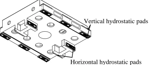
All the sliding contacts between the slide and machine base are based on the closed hydrostatic guideways with gap restrictors. The layout of the hydrostatic pads is described specifically in Fig. 6: there are 2 pairs of horizontal hydrostatic pads and 6 pairs of vertical ones located at the slide.
The gravity of slide is sustained by 6 pairs of vertical hydrostatic pads, which is illustrated in Fig.7. As far as one pair of vertical hydrostatic pads is concerned, EV=mg/6, and thickness values of upper
and lower vertical oil films are h0+εVh0 and h0-εVh0 respectively; the thickness values of horizontal
hydrostatic pads remain h0, for that EH=0.
Therefore, being the applications of the method provided by Section 2.2.5, the relative displacement of horizontal oil films: εH =0; and the vertical one can be obtained by solving the following equation:
V V2 V3
V V2 V3S e
2 3 2 3
V V V V V V
1 1
1 3 3 1 3 3
6
1 +1 1 1
1 3 3 1 3 3
mg
P A
(35)
Then the real εV value must be determined by the selection from the results of equation (35),
2.3.2 Dynamic viscosity of oil films dependent on temperature
With the influence consideration from temperature factor onto oil dynamic viscosity, the Reynolds V-T equation [22] is used into the methods provided in 2.2.2-2.2.3:
0
0
T T
e
(36)
Based on the equation (36) and for the feasibility of FE simulation method, the average dynamic viscosity value ηt of oil films in one pad at a moment t is approximately obtained as follows:
S 0
S out ( 1) 0 0 2 0 , 0 , 0 t T T T T t T e t e t (37)
Tout(t-1) stands for the output oil temperature of hydrostatic pad at the moment t-1. In transient FE
simulation, this value can be automatically acquired from the result of every substep by APDL.
3 Thermal FE Simulation Modeling of Hydrostatic Machine Feed Platform
3.1 CAE modeling and determination of simulation loads and boundary conditions
The main design parameters of the hydrostatic machine feed platform and its closed hydrostatic guideways with gap restrictors are listed in Tab. 1. Based on these parameters, the simplified CAE model of the hydrostatic machine feed platform is established in ANSYS. The distance between the slide and the proximal of machine base varies from 0 mm to 1000mm, and the increasing step is 200mm. Therefore, the machine stroke is divided into 5 parts averagely to predict and analyze thermal errors of the hydrostatic machine feed platform.
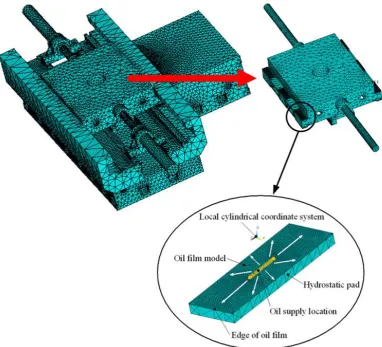
As shown in Fig.8, the sheet models are established to stand for oil films of hydrostatic pads. Then the established models are meshed, and the 3-D thermal surface effect elements are created between oil film models and the machine model, in order to simulate the convective heat transfer between oil films and the machine in ANSYS. The local cylindrical coordinate system is built up based on every oil film model. It is built with the central location of oil film model being its origin and the perpendicular direction to the model being its Z axis. Then the elements used to mesh oil film model are set abiding by this local cylindrical coordinate system. Thus, every oil film model is set to have a radial divergent outflow originated from oil supply location.
The values of mass flow rate, friction power, and stiffness of oil films are obtained by the methods provided in 2.2. Some fluid parameters in Tab.1 and the friction power, stiffness obtained are set up for elements of every oil film model, and the metal material parameters in Tab.1 are set up for elements of machine model. The oil supply temperature is exerted onto the oil supply location shown in Fig.8. The mass flow rate of oil films must be exerted on the whole oil film model by a heat flux method in the FE simulation. Specially, the mass flow rates and friction powers must be exerted as functions (with moment t being the independent variable) for the transient FE simulation. In these functions, the values of Tout_up(t-1), Tout_low(t-1) and Tout_hor(t-1) are acquired automatically from edges of
respectively study thermal characteristics of hydrostatic machine feed platform. Finally, in all these simulation conditions, the 3-dimensional displacement fix constraint is exerted to the bottom surface of the machine model, and the ambient temperature and gravity are exerted onto the machine model as a whole.
3.2 Results of FE simulations
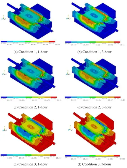
This paper concentrates on the temperature and horizontal/vertical thermal deformation results of transient FE simulations about hydrostatic machine feed platform. Figs. 9 and 10 show respectively its temperature and vertical thermal deformation fields of Conditions 1-3 at typical simulation steps (The distance between the slide and the proximal of machine base is 600mm). It can be seen from Fig.9 that, hydrostatic pads and their surrounding areas have higher temperature than other areas of the machine. With time increase, the temperature gradients are growingly obvious in all the 3 Conditions. Meanwhile, the temperature gradients in Condition 2 (TA=TS=20℃) are likely to be less obvious than
Condition1 (TA<TS) and Condition 3 (TA>TS). On the other hand, the vertical deformations caused
by oil film heat transfer of these 3 conditions are illustrated in Fig.10: With time increase, thermal deformations have the growing tendency, and the machine thermal deformation degree in Condition 2 is also lower than other 2 conditions. These thermal FE simulation results are the bases for the further discussions.
4 Experimental verifications
The reliability of the thermal FE simulation modeling method of hydrostatic machine feed platform is verified by experimental methods. These verifications are based on the Condition 1/2/3 (TA=17℃
/20℃/23℃, TS=20℃) defined above. This section introduces the experimental procedure and the
verification of the studied FE simulation modeling method.
4.1 Experimental procedure
As shown in Fig.11, verification experiments were done by this method: When the hydrostatic machine feed platform was working at a low feeding velocity, temperatures and thermal deformations were continuously measured by thermal resisters and the laser interferometer respectively. The temperature signals from the former were conveyed by signal gathering system to the host computer, and thermal deformation values from the latter were directly received by the host computer.
Specially, the locations of sensors mentioned on the machine are also illustrated in Fig.11: Thermal resisters are located to positions A-D: Temperatures of position A and B (TPA and TPB) stand for the oil
film temperature, Temperature of C (TPC) is measured to be ambient temperature, and temperature of
D ( TPD) corresponds to the oil output temperature of hydrostatic pads. On the other hand, the reflector
of laser interferometer is located at Position O, in order to measure the horizontal and vertical thermal deformations of the working slide. The setting method of the laser interferometer is shown in Fig. 12. Experiments were done in Condition 1-3 defined above (TA=17℃/20℃/23℃, TS=20℃) respectively,
to verify comprehensively the thermal FE simulation modeling method of hydrostatic machine feed platform. The measurements in every defined condition would not be terminated until the changing scales of its signals in last hour were less than 15% of the ones in first hour [21].
4.2 Comparisons between experimental data and simulation results
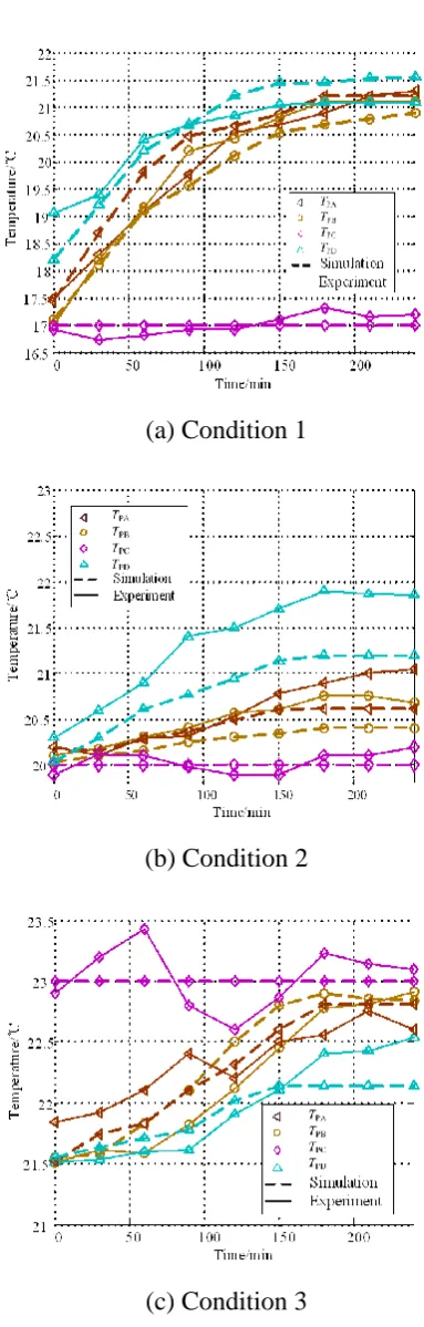
According to the locations A-D in Fig. 11, the simulated temperature values are obtained from the machine temperature fields of 3 defined conditions in Fig. 9. They are compared with the measured
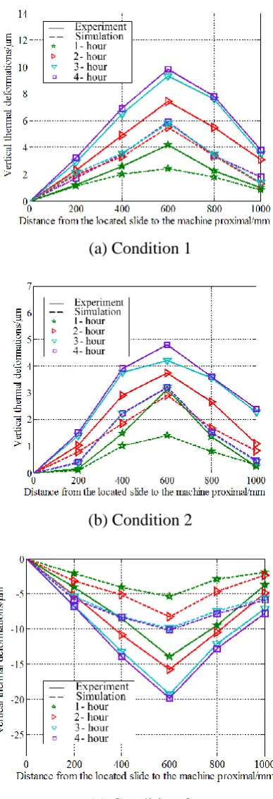
TPA-TPD of 3 defined conditions respectively in Fig. 13. Meanwhile, thermal deformation values of
10. Both the obtained horizontal (Y direction) and vertical (Z direction) thermal deformations are compared with the corresponding measured values of 3 defined conditions respectively. Fig. 14 shows the comparisons of the vertical simulated thermal deformations and their measured values. It can be clarified by Fig. 13 and 14 that, the simulated results are in agreement with the corresponding experimental data in 3 defined conditions. These consistencies can verify the reliability of the introduced thermal FE simulation modeling method of hydrostatic machine feed platform.
5 Analyses and Discussions
Some further analyses based on FE simulation results in Section 3 are done in this section. On one hand, the oil film heat transfers in Conditions 1-3 are analyzed and compared. The difference of them is the dominant factor causing thermal deformation difference of hydrostatic machine feed platform. On the other hand, thermal deformation FE results of the platform lead to its thermal error prediction methods. The association between the predicted machine thermal errors and the oil film heat transfer is analyzed and discussed.
5.1 Oil film heat transfer discussion of hydrostatic machine feed platform
The thermal deformation of hydrostatic machine feed platform is attributed to the oil film heat transfer towards the platform. The oil output temperatures (Tout) of Condition 1-3 are obtained based
on the temperature FE results of hydrostatic machine feed platform respectively. Then (TS+Tout)/2 is
used to approximately present the average oil film temperature. Furthermore, the temperature gradient between oil films and the environment is:
S out
A
2
T T T T
Based on this method above, the time-varying temperature gradients from oil films towards the environment of Condition 1-3 are illustrated and compared in Fig. 15. This figure shows: Conditions 1-3 have growing temperature gradients with time increase. But the one of Condition 2 (TA=TS=20℃)
is the least and close to 0, compared with the other 2 conditions. The initial temperature of hydrostatic machine feed platform in operation is generally assumed to be same with ambient temperature. When the hydrostatic machine feed platform is running, the oil film heat transfer is generally through the machine structure and dissipated in the ambient air convection. This heat transfer brings the time-varying machine structure temperature, and this heat transfer is the critical factor causing machine thermal deformation. The heat transfer scale is determined by the temperature gradients from oil films towards the environment. (The negative temperature gradient of Condition 3 in Fig. 15 means its reverse heat conveying direction.). Because Condition 2 has the least temperature gradient scale, it has the least heat transfer scale to cause machine thermal deformation. That is the reason for that the machine thermal deformation in Condition 2 is lower than the other 2 conditions, which is presented in Section 3.2. Therefore, Condition 2 (TA=TS=20℃) is more beneficial than the other 2
conditions (TA<TS and TA>TS) in cutting down the machine thermal deformation.
5.2 Thermal errors prediction of hydrostatic machine feed platform
5.2.1 Methods for thermal errors prediction of hydrostatic machine feed platform based on FE
simulation results
Thermal errors of hydrostatic machine feed platform △Y, △Z, δY, δZ shown in Fig.4 can be
These thermal deformations are obtained from the FE simulation results in Section 3.2. As shown in Fig. 16, parallel lines 1 and 2 are located with the minimum distance to include all these thermal deformation values. Then the straightness error and rotating error of hydrostatic machine feed platform can be predicted [20]. According to the Cartesian coordinate system for hydrostatic machine feed platform in Fig.5, the distance d of the 2 parallel lines in Fig.16 is predicted as △Z, and the angle α caused by 2 parallel lines with horizontal axis is predicted as δY. They are the predicted thermal
errors of hydrostatic machine feed platform.
5.2.2 Machine thermal error variations caused by the temperature gradient from oil film to
environment
The method mentioned in 5.2.1 can be applied onto the thermal straightness (horizontal and vertical) error and angle error estimations of hydrostatic machine feed platform in Condition 1-3. Thus, the influence from quantitative comparison result between TA and TS onto thermal errors of hydrostatic
machine feed platform can be summarized based on the thermal simulation results of hydrostatic machine feed platform.
Fig. 17 and Fig. 18 show the comparisons of thermal errors △Y, △Z, δY, δZ in Conditions 1-3,
based on the prediction method in 5.2.1. It can be seen from the comparisons that, Condition 2 has the smaller thermal straightness errors and angle errors (△Y=3.94μm, △Z=2.8μm; δY=-6.3e-007rad, δZ=-3.1333e-007rad) than the other 2 conditions, because Condition 2 has the minimum heat transfer
scale through the machine structure in these 3 conditions. This scale is determined by the temperature gradient from oil films to environment, and the oil film temperature relies on oil supply temperature. So the machine thermal errors are determined by the quantitative comparison result of oil supply temperature and ambient temperature, then this relative oil supply temperature to ambient temperature should be diminished as possible to reduce machine thermal errors.
accuracies of them are generally in the order of micron or submicron, thermal influence to machine accuracy from the hydrostatic guideways cannot be ignored (TA=TS=20℃:△Y=3.94μm, △Z=2.8μm; δY=-6.3e-007rad, δZ=-3.1333e-007rad), and must be taken into the account in design and error
compensation about hydrostatic machine tools.
6 Conclusions
A comprehensive thermal simulation modeling method of hydrostatic machine feed platform is presented in this paper, so as to predict its thermal characteristics and study the reducing method of its machine thermal errors. This method includes the theory analyses about the simulation loads of closed hydrostatic guideways and the thermal FE simulation of hydrostatic machine feed platform. Specially, the former is guided by a friction power heat model of viscous hydraulic oil flowing between parallel planes based on Bernoulli equation. The main conclusions of the study are listed as follows:
(1) In machine design phase, the presented thermal simulation modeling method of hydrostatic machine feed platform is reliable and accurate to predict and analyze its thermal characteristics, which is verified by experiments.
(2) Based on the thermal FE simulation results of the hydrostatic machine feed platform in this paper, machine feed thermal errors △Y, △Z, δY, δZ can be calculated and predicted. For high-precision
or ultra-precision machine tool whose desired accuracy is in the order of micron or submicron, hydrostatic machine feed errors caused by thermal factors generally cannot be ignored.
Acknowledgements
This paper is supported by the state S&T projects for upmarket NC machine and fundamental manufacturing equipment of China (No. 2014ZX04014-011)
References
[1] Wang ZW, Zhao WH, Chen YL, Lu BH (2013) Prediction of the effect of speed on motion errors in hydrostatic guideways. Int J Mach Tools Manuf 64:78-84
[2] Xue F, Zhao WH, Chen YL, Wang ZW (2012) Research on error averaging effect of hydrostatic guideways. Precis Eng 36: 84-90
[3] Yang Z, San AL, Childs DW (1996) Thermal effects in liquid oxygen hydrostatic journal bearings. Tribol T 39(3): 654-662
[4] Sharma SC, Kumar V, Jain SC, Nagaraju T, Prasad G (2002) Thermohydrostatic analysis of slot-entry hybrid journal bearing. Tribol Int 35(9): 561-577
[5] Sharma SC, Kumar V, Jain SC, Nagaraju T (2003) Study of hole-entry hybrid journal bearing system considering combined influence of thermal and elastic effects. Tribol Int 36(12): 903-920 [6] Park CH, Oh YJ, Hwang JH, Lee DW (2002) Experimental analysis on thermal characteristics of
hydrostatic guideway for precision positioning. 1st Korea Japan Conference of Positioning Technology: 52-57
[7] Kumar V, Sharma SC, Jain SC (2004) Stability margin of hybrid journal bearing: influence of thermal and elastic effects. J Tribol - T ASME 126(3): 630-634
[8] Suzuki H, Urano K, Kumehara H, Kusumoto K (2009) Minimizing thermal deformation of high-precision machine tool induced by hydraulic oil of hydrostatic bearings. Seimitsu Kogaku Kaishi/Journal of the Japan Society for Precision Engineering 75(9): 1106-1111
[9] Kapur VK, Verma K (1979) Simultaneous effects of inertia and temperature on the performance of a hydrostatic thrust bearing. Wear 54(1): 113-122
[11]Zhang JB, Chi CQ (1997) Analysis of thermal effects in shallow recess-step hydrostatic and hydrodynamic oil bearing. Journal of Beijing University of Aeronautics and Astronautics 23(3): 390-394
[12]Zhang GY, Yuan XY (2006) A theoretical study on three - dimensional pressure distributions and temperature field of water-lubricated hydrostatic journal bearings. Lubrication Engineering 8: 4-7 [13]Fu YL, Zhu J (2006) Three-dimensional temperature field analysis of hybrid journal bearing.
Lubrication Engineering 2: 115-117
[14]Chen DJ, Bonis M, Zhang FH, Dong S (2011) Thermal error of a hydrostatic spindle. Precis Eng 35: 512-520
[15]Jiang Y, Hou GA, Sun T (2011) Thermal finite element analysis of hydrostatic guide. Aviation Precision Manufacturing Technology 47(5):23-25
[16]Wang JH, Du W, Liu ZF, Cai LG (2013) The thermal characteristics analysis of a super hydrostatic guideway. Applied Mechanics and Materials 248: 162-166
[17]Su H, Lu LH, Liang YC, Zhang Q, Sun YZ (2014) Thermal analysis of the hydrostatic spindle system by the finite volume element method. Int J Adv Manuf Tech 71:1949-1959
[18]Wang ZW, Zhao WH, Li BQ, Zhang J, Lu BH (2011) Fluid-structure interactions (FSI) on static characteristics of hydrostatic guideways. 2011 IEEE International Symposium on Assembly and Manufacturing, ISAM 2011
[19]Shamoto E, Park CH, Moriwaki T (2001) Analysis and improvement of motion accuracy of hydrostatic feed table. CIRP Ann-Manuf Techn 50(1): 285-290
[20]Yang JG, Fan KG, Du ZC (2013) Real-time error compensation of CNC machine tools. China machine Press, Beijing
[21]ISO 230-3: 2001, IDT. Test code for machine tools--Part 3: Determination of thermal effects [22]Buscaglia GC, Jai M (2004) Homogenization of the generalized Reynolds equation for ultra-thin
Fig. 1. Theory analyses for thermal simulation modeling of hydrostatic machine feed platform
[image:27.595.208.389.427.502.2](a) Axonometric drawing
[image:28.595.162.432.69.232.2](b) Vertical projection
Pump Oil returning
chute
Gap restrictors Recess Land
Guide rail
Oil output holes
Oil supply
hole
Hydrostatic pad 1
h0+εh0
h0-εh0 Hydrostatic
pad 2 Oil input hole
E F2
[image:29.595.151.447.69.359.2]F1
Fig. 4. Operational principle of closed hydrostatic guideways with gap restrictors
[image:29.595.115.485.511.685.2]Horizontal hydrostatic pads Vertical hydrostatic pads
Fig. 6. Layout of hydrostatic pads on slide
mg h0-εVh0
h0 h0+εVh0
[image:30.595.113.485.458.604.2](a) Condition 1, 1-hour (b) Condition 1, 3-hour
(c) Condition 2, 1-hour (d) Condition 2, 3-hour
[image:32.595.92.510.64.618.2](e) Condition 3, 1-hour (f) Condition 3, 3-hour
(a) Condition 1, 1-hour (b) Condition 1, 3-hour
(c) Condition 2, 1-hour (d) Condition 2, 3-hour
[image:33.595.90.515.67.626.2](e) Condition 3, 1-hour (f) Condition 3, 3-hour
Fig. 11. Experimental method
[image:34.595.181.415.557.710.2](a) Condition 1
(b) Condition 2
[image:35.595.195.387.63.664.2](c) Condition 3
(a) Condition 1
(b) Condition 2
[image:36.595.198.392.76.643.2](c) Condition 3
Fig. 15. Time-varying temperature gradients from oil films to environment
[image:37.595.196.511.393.618.2]
Fig. 17. Comparisons about predicted thermal straightness errors △Y, △Z
[image:38.595.146.430.409.664.2]Tab. 1. Design parameters of hydrostatic machine feed platform and its closed hydrostatic guideways with gap
restrictors
Design parameters Values
Mass of slide m (kg) 2.0582e3
Density of metal material of machine ρM(kg/m
3
) 7350
Thermal conductivity of metal material of machine kM (w/(m·K)) 35.7
Specific heat of metal material of machine cM (J/(kg·K)) 460
Stiffness of metal material of machine JM (N/m) 1.2e11
Poisson's ratio of metal material of machine μ 0.125
Linear expansion coefficient of metal material of machine α 10e-6
Design pressure ratio β 2
V-T index coefficient γ (used in Reynolds V-T equation) 0.468
Supply pressure of hydraulic oil PS (Pa) 2.4e6
Design thickness of oil films h0 (m) 2e-5
Density of hydraulic oil ρ (kg/m3) 865
Specific heat of hydraulic oil c (J/(kg·K)) 2.1e3
Dynamic viscosity of hydraulic oil η (Pa·s) η0=1.27e3
(T0=20℃)
Width of gap restrictor WG (m) 2e-3
Length of gap restrictor LG (m) 7e-2
Radial scale of land WL (m) 8e-3
Average circumferential scale of land LL (m) 0.6
Effective bearing area Ae (m 2