Type of the Paper: Article 1
Electrospun produced 3D matrices for covering of
2
vascular stents: paclitaxel release depending on fiber
3
structure and composition of the external
4
environment
5
Konstantin A. Kuznetsov1, 2*, Alena O. Stepanova1, 2, Ren I. Kvon3, Timothy E.L. Douglas4, 5, Nikita
6
A. Kuznetsov1, Vera S. Chernonosova1, 2, Ivan A.Zaporozhchenko 1, 2, Maria V.Kharkova1, Irina
7
V.Romanova1, Andrey A. Karpenko2 and Pavel P. Laktionov1, 2
8
1 Institute of Chemical Biology and Fundamental Medicine, Siberian Branch, Russian Academy of Sciences,
9
Novosibirsk, 630090 Russia
10
2 Meshalkin National Medical Research Center, Ministry of Health of the Russian Federation, Novosibirsk,
11
630055 Russia
12
3 Boreskov Institute of Catalysis, Siberian Branch, Russian Academy of Sciences, Novosibirsk, 630090 Russia
13
4 Engineering Department, Lancaster University, Lancaster LA1 4YW, United Kingdom
14
5 Materials Science Institute (MSI), Lancaster University, Lancaster LA1 4YW, United Kingdom
15
* Correspondence: [email protected]; Tel.: + +7-383-363-51-43 16
17
Abstract: Paclitaxel is a natural, highly lipophilic anti proliferative drug widely used in medicine.
18
We have studied the release of tritium-labeled paclitaxel (3H-PTX) from matrices destined for the 19
coating of vascular stents and produced by the electrospinning method from the solutions of
20
polycaprolactone (PCL) with paclitaxel (PTX) in hexafluoisoropropanol (HFIP) and/or solutions of
21
PCL with PTX and human serum albumin (HSA) in HFIP or HIFP-dimethyl sulphoxide (DMSO)
22
blend. The release of PTX has been shown to depend on the solvent and the composition of
23
electrospinning solution, as well as the composition of the surrounding medium, particularly the
24
concentration of free PTX and PTX-binding biomolecules present in human serum. It was shown
25
that 3D matrices can completely release PTX without weight loss. Two-phase PTX release from
26
optimized 3D matrices was obtained: ~27% of PTX was released in the first day, another 8% were
27
released over the next 26 days. Wherein ~2.8%, ~2.3%, and ~0.25% of PTX was released on day 3, 9,
28
and 27, respectively. Considering PTX toxicity, the rate of its diffusion through the arterial wall,
29
and the data obtained the minimum cytostatic dose of the drug in the arterial wall will be
30
maintained for at least three months.
31
Keywords: drug release; electrospinning; paclitaxel; polycaprolactone; 3D matrix.
32 33
1. Introduction
34
Nano- and microfiber-assisted drug delivery is actively studied worldwide. It is used 35
in specific areas, such as tissue engineering [1] but also to solve general problems of drug 36
delivery, such as enhancement of drug solubility [2] and tailoring of the kinetics of drug 37
release [3]. Electrospinning (ES), i.e., the formation of polymer filaments from melts or 38
solutions of polymers in a strong electric field, is a suitable method for the incorporation of 39
drugs into the fibers and is frequently used for production of drug-enriched matrices. Nano- 40
and microfibers produced by ES have a large surface area. Furthermore, their porosity, 41
hydrophilicity/hydrophobicity, ability participate in to ionic and nonionic interactions, as 42
well as diameter and ultrastructure of the fibers can be tailored. In addition, it is possible to 43
use polymers possessing different degradation rates [4]. The most convenient is ES of 44
polymer solutions which can employ one or more polymers and drugs, emulsions and 45
suspensions of drugs [5]. Fiber surface and porosity are usually modified by adding 46
water-soluble biopolymers or low-molecular-weight components to the ES solution or using 47
water- or thermo-induced phase separation [6]. The fibers of different structure can be 48
produced by ES, including hollow, coaxial, and (multi)double-layered fibers combined with 49
drugs introduced in different manners. These fibers can be produced simultaneously forming 50
multi-fiber matrices or several different types of fibers, which can be arranged layer-by-layer 51
in order to form multilayered matrices with different properties assigned to each layer [7]. 52
The benefits of this approach are readily acknowledged, and electrospinning is widely used 53
to fabricate drug-loaded materials, including bactericidal antibiotic dressings [8], growth 54
factor-loaded 3D matrices capable of inducing cell proliferation and wound healing [9], and 55
matrices with cytostatic drugs, used as anti-adhesive membranes [10]. 56
Recently, electrospun matrices were suggested as coatings for bare-metal esophageal 57
[11] and vascular stents [12]. The high incidence of restenosis requires the reassessment and 58
improvement of current practices for the remodeling of stented arterial regions with 59
bare-metal stents [13]. Restenosis is caused by the proliferation of smooth muscle cells of the 60
arterial wall, endothelial cells or cells of atherosclerotic plaques induced by the mechanical 61
action on the remodeled vessel, damage of the endothelial layer and other surrounding cell 62
layers/tissues [14]. Induction of local inflammation in the stent region also promotes cell 63
proliferation and neointima growth [15]. Drug-eluting stents covered with anti-proliferative 64
or anti-inflammatory drugs such as sirolimus and paclitaxel (PTX) were proposed to reduce 65
the proliferation of surrounding cells. PTX is a natural, highly lipophilic, water-insoluble 66
compound, which exhibits a cytotoxic antimitotic effect by activating the assembly of 67
microtubules from tubulin dimers, stabilizing microtubules, and inhibiting the reorganization 68
of the microtubular network in the interphase and during mitosis [13]. The lipophilicity of 69
PTX allows its accumulation in the altered atheromatous vascular wall. The usual dose of 70
PTX in paclitaxel-eluting stents is approximately 3 µg/mm2 [16]. Excessive doses were 71
shown to induce the formation of aneurysms [17]. Therefore, blending of PTX with polymers 72
was proposed to increase the effect of PTX i.e. short-term and long-term toxicity, while using 73
lower concentrations of PTX. For example, the Eluvia stents (Boston Scientific Corporation, 74
PTX with poly(vinylidene fluorideco-hexafluoropropylene) only contain 0.167 µg/mm2 PTX 75
[18]. 76
In this work, we studied the release of PTX from the 3D matrices prepared from a 77
solution of polycaprolactone (PCL) containing human serum albumin (HSA) intended for the 78
coating of bare-metal stents. Such matrices have good mechanical characteristics and an 79
loads on struts after stent expansion during installation. Moreover, the slow degradation rate 81
of PCL may allow it to provide a lasting mechanical protection of the vessel lumen from 82
stenosis. It is implemented in a similar way in the Inspire MDCGuard™ stents [19]. Release 83
of PTX from matrices can be slowed by adding HSA, which binds PTX at Kd = 1.43 ×
84
104 M-1 [20] and acts as the main carrier of PTX in the human body. In addition, HSA has
85
been shown to reduce platelet adhesion and increase thromboresistance and 86
hemocompatibility of blood-exposed surfaces [21, 22]. With the task of creating a coating 87
that can prevent cell proliferation for as long as possible, we developed and fabricated 3D 88
matrices enabling prolonged PTX delivery. 3D matrices were produced by electrospinning 89
and characterized by general methods including tensile strength, SEM, XPS, contact angle, 90
ets, PTX release was studied using tritium-labeled PTX. 91
2. Materials and Methods
92
2.1. Production and quality control of tritium-labeled paclitaxel 93
Tritium-labeled PTX (3H-PTX) was synthesized by thermoactivated tritium exchange
94
as described earlier [23]. 3H-PTX was purified from by-products by reverse phase
95
chromatography on a C18 column using a gradient of acetonitrile in water (25-100%). The 96
radiochemical purity of the resulting compound was evaluated by autoradiography after thin 97
layer chromatography (TLC) on Kieselgel 60 F254 plates (Merck, Germany, 25 Alufolien 20 98
x 20 cm) in a chloroform-methanol-water mixture (19 : 1 : 0.1, Rf ~0.7). Radioactivity of the 99
preparation was measured on a Tri-Carb 2800 TR β-counter (PerkinElmer, USA) in a 100
“ULTIMA GOLD LTT” scintillator (Perkin Elmer, USA). An aliquot of the sample (0.1 mL) 101
was thoroughly mixed with a scintillator (0.9 mL), and radioactivity was measured at the 102
same time after preparation of the mixture. 103
2.2. Preparation of 3D matrices by electrospinning. 104
Electrospinning solutions were prepared using stock solutions of 9% PCL and 1% 105
HSA (Sigma-Aldrich, USA) in 1,1,1,3,3,3-hexafluoroisopropanol (HFIP, Sigma-Aldrich, 106
USA). The HSA concentration in matrices is given as weight percentage (wt/wt) of total 107
matrix weight. PTX (Sigma-Aldrich, USA) was dissolved in HFIP or DMSO 108
(Sigma-Aldrich, USA) and added to the matrix (~0.46 μg/cm2, which corresponds to 0.36
109
μg/disk). DMSO (3 or 6%, v/v) was added to the solution of polymers. 3H-PTX was diluted
110
with unlabeled PTX to provide at least 26000 cpm/cm2 (or 20000 cpm/disk, 10 mm diameter
111
disk, ~0.785 cm2). To produce the 3D matrices with 3H-PTX, a homemade electrospinning 112
device with an airproof chamber and exhaust HEPA filter was used, equipped with a 113
Spellman SL 150 (30 kV, Spellman, USA) power supply. Matrices of thickness of 150–180 114
µm were prepared using a drum collector 2 cm in diameter and 5.2 cm in length (32.6 cm2)
115
under the following conditions: feed rate, 1.2–1.4 mL/h; capillary-collector distance, 19–20 116
25–35%. After fabrication, 3D matrices were removed from the collector, dried in vacuum 118
under 10 Pa for 12 h and stored in sealed zip-lock polyethylene containers at 4°C. 119
2.3. Characterization of matrices 120
2.3.1. Mechanical testing of matrices 121
Strain-stress diagrams were obtained using a universal Zwick/Roell Z100 (Germany) 122
test bench as described in ISO 7198:1998 [24]. Electrospun matrices were carefully cut into 123
10×50 mm rectangular shapes and placed between holders at a distance of 2–2.5 cm. Tensile 124
strength testing was conducted at a rate of 10 mm×min−1 at room temperature (21–23°C). At 125
least four specimens of each sample were tested. The residual load after two-fold elongation 126
of matrices was measured in the same way, with the difference that after matrix elongation, 127
the load was removed, the clamps of the tearing machine were returned to their original 128
position (l0), and the load was re-measured after two-fold elongation of the matrix.
129
2.3.2. Study of 3D matrix surface microstructure 130
The microstructure of the matrix surface was studied by scanning electron 131
microscopy (SEM) as described earlier [25]. The fiber diameter and pore size were evaluated 132
from the SEM images according to ISO 7198:1998 [24]. To assess the stability of the fiber 133
structure, the 3D matrices were incubated in phosphate buffered saline (PBS) 134
(Sigma-Aldrich, USA) or human plasma at room temperature for 27 days. After the 135
incubation, the matrices were rinsed with Н2О, air-dried, and examined by SEM.
136
2.3.3. X-ray photoelectron spectroscopy 137
The X-ray photoelectron spectroscopy (XPS) study was performed on a SPECS 138
electron spectrometer equipped with a PHOIBOS-150 MCD-9 hemispherical analyzer and a 139
non-monochromatic twin Mg-Al source (SPECS GmbH, Germany). To avoid thermal 140
degradation of the sample, the X-ray gun was positioned at a distance of 30 mm from the 141
sample holder and operated at MgKα irradiation power of 70W or less. The spectra were 142
recorded with pass energy set to 50 eV (survey scans) and 10 eV (high-resolution ones). 143
Before the measurements, the energy scale was calibrated using the Au4f7/2 (84.00 eV) and
144
Cu2p3/2 (932.67 eV) peaks from gold and copper foils. The residual gas pressure during the
145
spectra acquisition did not exceed 3 × 10⁻⁷ Pa. The samples were mounted on steel sample 146
holders by using 3M® copper conductive double-sided adhesive tape. Quantitative data 147
processing was performed using the XPSPEAK software version 4.1 and atomic sensitivity 148
factors reported previously [26]. To study the influence of medium on 3D matrices, they 149
were incubated in water or ethanol for 48 h, as described in 2.4, rinsed, air-dried, and stored 150
as described in 2.2. 151
2.3.4. Additional physicochemical characteristics of matrices 152
The contact angle was measured on a Drop Shape Analyzer–DS A25 (Kruss GmbH, 153
second). The porosity of the matrices was evaluated using matrix volume and PCL density 155
according to the formula: 156
Porosity (%) = [1 – Da/Dp] × 100, where Da is apparent density (matrix weight/matrix
157
volume) and Dp is the polymer density.
158
SEM data was also used for porosity calculations as described in ISO 7198:1998 159
according to the formula: 160
Porosity (%) = [Ap/(Am + Ap)] × 100, where Ap is pore area and Am is matrix area.
161
Water absorption and weight loss of matrices were evaluated as described in ISO 7198:1998 162
according to the formulas: 163
Water absorption (%) = (Ww – Wo)/Wd × 100;
164
Weight loss = (%) = (Ww – Wd/Wo) × 100, where Ww is weight after wetting, Wo is
165
weight before wetting, and Wd is weight after wetting and drying under vacuum. The
166
accuracy of measurements considering 3D matrices weight and accuracy of weighting was 167
about 1.5%.Weight loss was evaluated after 27 days of incubation of 3D matrices in PBS as 168
described in 2.3.2. 169
The drying rate of the matrices was evaluated after soaking the matrices in water for 170
24 h, followed by weight measurements on a microbalance with an accuracy of ±0.1 mg. 171
2.4. Assessment of paclitaxel release 172
To evaluate the PTX release, 10 mm disks were excised from matrices by die cutting, 173
weighed with an accuracy of ±0.1 mg, and placed in wells of a 48-well plate. Disks were 174
covered with 250 µL of PBS or EDTA-stabilized human plasma (HBP). The plate was sealed 175
with a sealed adhesive film(Microseal® 'B' PCR Plate Sealing Film, adhesive, Bio-Rad, 176
USA) to prevent drying, followed by incubation on a Titramax 1000 shaker (Heidolph, 177
Germany) at 37°C and platform rotation speed of 200 rpm for different times up to 27 days. 178
Two types of 3Н-PTX release kinetics were evaluated. For Series 1 the matrices were 179
incubated with the solution for 20 min, 60 min, 3 h, 9 h, 27 h, 3 days, 9 days, and 27 days 180
without medium replacement. For Series 2 at each time point the supernatant was removed, 181
the matrix was rinsed, and incubated in a fresh replacement of the respective solution until 182
the next time point, when the same procedure was repeated. After the incubation, the 183
matrices were washed with distilled water and air-dried at room temperature. Radioactivity 184
of the supernatants was measured in duplicate as described in section 2.1. The concentration 185
of PTX in the solution was calculated from the specific radioactivity of the preparation, 186
assuming that one disc contained ~0.36 μg of PTX. 187
The influence of the matrix deformation on the 3Н-PTX release was studied as 188
follows. A strip of a 3D matrix was fixed in clamps, the distance between the clamps was 189
measured, and subsequently matrix was slowly stretched with a screw to double the 190
measured distance. After removing the load, linear sizes of the strip were measured in order 191
and 3Н-PTX release was evaluated as described. All experiments were performed in 193
duplicate. 194
2.5.Statistical processing of data
195
Microsoft Excel 2010 was used to handle and process the experimental data. 196
Statistical analyses were performed using the Statistica 7.0 package (StatSoft Inc., USA). 197
3. Results and Discussion
198
3.1. Synthesis of radioactively labeled PTX 199
3H-PTX was synthesized by the thermoactivated tritium exchange as described earlier
200
[23]. The RP-HPLC-purified 3Н-PTX preparation was obtained with a specific radioactivity 201
of 1.5 mCi/mL (~0.3 Ci/mМ of PTX). According to the TLC data, the compound was 202
homogenous and detected as one spot on the autoradiograph with Rf as non labeled PTX. 203
Preliminary tests were performed to determine the optimal conditions for the measurement of 204
the sample radioactivity in PBS and HBP. It was shown that the counting efficiency is 205
inversely proportional to the volume of the sample; after the addition of the sample to 206
scintillator at a ratio of 1:10 (v:v) no turbidity of the solution was detected, along with 207
maximal efficacy of tritium detection independently of sample origin (H3 was detected with 208
practically equal efficacy both in PBS and in human plasma). Therefore, the radioactivity of 209
all samples was evaluated in the same way, i.e., 0.1 mL of the sample was diluted in the 210
scintillator up to a total volume of 1 mL. The molar concentration of PTX was evaluated 211
using the total specific radioactivity of the (3Н-PTX + PTX) preparation introduced into the
212
matrix, which was ~47000 cpm/nM. 213
3.2. Electrospinning and characterization of 3D matrices prepared from different mixtures of 214
PCL with HSA and solvents 215
HSA is known to be the main protein in the blood plasma, which binds PTX into two 216
types of complexes with a common binding constant K=1.43 × 10⁴ M-1 [20] and carries it in 217
the blood. In electrospun 3D matrices prepared from PCL-HSA mixtures a significant 218
amount of matrix-bound HSA is located on the fiber surface and remains exposed for a long 219
time [25]. We consider that such matrices could be used as a coating for bare-metal vascular 220
stents and delivery of PTX into the vascular wall. 221
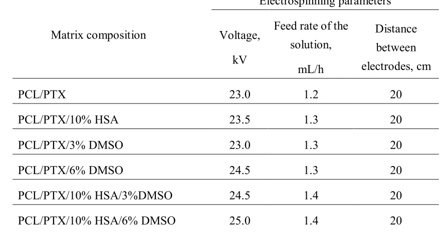
Conditions for preparation of matrices from PCL with HSA, PTX, and DMSO by 222
electrospinning are presented in Table 1. 223
224
225
226
227
Table 1. Electrospinning conditions for fabrication of 3D matrices 229
Matrix composition
Electrospinning parameters
Voltage,
kV
Feed rate of the
solution,
mL/h
Distance
between
electrodes, cm
PCL/PTX 23.0 1.2 20
PCL/PTX/10% HSA 23.5 1.3 20
PCL/PTX/3% DMSO 23.0 1.3 20
PCL/PTX/6% DMSO 24.5 1.3 20
PCL/PTX/10% HSA/3%DMSO 24.5 1.4 20
PCL/PTX/10% HSA/6% DMSO 25.0 1.4 20
230
The strength of the PCL-based matrices was 3˗5.1 MPa depending on the 231
composition of the electrospinning solution. The regions of elastic and plastic deformation 232
for PCL-HSA matrices were 8±1.5% and 290 ±16%, respectively, which indicated their 233
strength and elasticity compared to matrices prepared without the protein. Residual load after 234
two-fold elongation was 1.4 ± 0.16 to 0.35 ± 0.07 MPa in the dry matrices and 1.0 ± 0.11 to 235
0.26 ± 0.24 MPa in the wet matrices prepared from PCL/PTX/10% HSA and PCL/PTX/10% 236
HSA/6% DMSO, respectively. The strength of the coronary artery wall is 1–2 MPa 237
depending on the age of the donor and the presence of atherosclerotic lesions [27]. The 238
thickness of the coronary artery wall is at least 2 mm [28], and the thickness of the stent 239
coating is 0.1–0.15 mm. Therefore, the residual load in the coating of the stent after its 240
installation does not exceed 5% of the loadprovided by the vascular wall. If the coatings for 241
the metal stents are prepared from the solutions of PCL with HSA and DMSO, the load 242
applied by the matrix on the stent struts will be no more than 1.5–2% of the load from the 243
wall of the stented artery. Hence, from a mechanical point of view, the applicability of 244
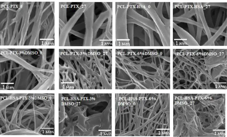
246
Figure 1. Microstructure of 3D matrices (SEM, ×3000 magnification). The digit following
247
the matrix composition indicates the incubation time of the matrices in PBS. 248
SEM analysis revealed that all prepared matrices were composed of microfibers with 249
diameter determined by the composition of the electrospinning solution (Figure 1). Matrices 250
from PCL and PCL with HSA consisted of fibers with average diameters of 0.32 and 0.56 251
µm, respectively (Table 2). The addition of DMSO decreased the average fiber diameter 252
(Figure 1, Table 2). The diameter of the fibers in 5% PCL/PTX/3% DMSO/HSA matrices 253
was 0.37 ± 0.08 µm, which was the highest of all matrices with DMSO (from 0.13 to 0.19 254
µm). The fibers of all matrices had a smooth surface. Using × 40000 magnification, with 255
which structures as small as 20 nm can be resolved, no pores of diameter 10-20 nm could be 256
detected on the fiber surface, although a slight roughness probably caused by the drying of 257
the solvent was observed. 258
259
260
261
262
263
264
265
266
267
268
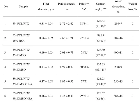
[image:8.595.111.485.90.316.2]Table 2. Physico-chemical properties of 3D matrices 270
No Sample Fiber
diameter, µm
Pore diameter,
µm
Porosity,
%*
Contact
angle, o**
Water
absorption,
%
Weight
loss, %
1 5% PCL/PTX 0.31 ± 0.04 5.72 ± 2.42 78/54,1 127.33
(±1.30)° 294±7 0
2 5% PCL/PTX/
10% HSA 0.56 ± 0.09 2.66 ± 1.21 77/61.4
88.89
(±3.03)° 589±16 0
3 5% PCL/PTX/
3% DMSO 0.19 ± 0.03 2.01 ± 0.73 78/65
128.30
(±2.18)° 400±11 0
4 5% PCL/PTX/
6% DMSO 0.13 ± 0.02 0.97 ± 0.32 80/76.6
132.35
(±3.11) ° 238±9 0
5 5% PCL/PTX/
3% DMSO/HSA 0.37 ± 0.08 1.97 ± 0.52 77/71
124.73
(±3.49)° 750±13 0
6 5% PCL/PTX/
6% DMSO/HSA 0.16 ± 0.03 1.35 ± 0.40 79/61.3
120.52
(±2.66)° 883±15 0
The data are presented as the mean ± error of the mean; 271
*the first and the second numbers are porosity calculated from the apparent matrix density 272
and the SEM data, respectively; 273
**the contact angle was evaluated as a mean of at least five measurements in different parts 274
of the matrix. 275
276
The porosity of the fiber surface and the dependence of the pore size on 277
electrospinning conditions, such as a solvent, polymer, and wetting, were studied previously 278
[29, 30]. It was shown that pore formation is caused by the evaporation of the solvent and 279
cooling of the surface of a newly formed fiber (thermally induced phase separation, TIPS) 280
accompanying with condensation of water vapor (water induced phase separation, WIPS). 281
The occurrence of pores only on the fiber surface as demonstrated previously by TEM and 282
atomic force microscopy (AFM) is evidence in favor of WIPS rather than TIPS as the main 283
determinant of fiber porosity [31]. Obviously, the interplay of solvent diffusion in polymers, 284
polymer solubility in solvents, and phase transitions occurring for several polymers in the 285
same solvent can play an important role in the formation of the structure and the surface of 286
3D matrices up to ~100˗1000 m2/g [30], which undoubtedly will affect the rate and extent of 288
drug release. 289
Notably, it is often postulated that the nanopores in fibers are tortuous rather than 290
straight and have a significant length [32]. Their size depends, among other factors, on the 291
type of solvent as well as protein concentration and solubility. It should be noted that in the 292
solvent systems, such as dimethylformamide/dichloromethane or dimethylformamide/ 293
chloroform [33], proteins are poorly dissolved and are present in suspension. This fact can 294
significantly influence the fiber structure, exposition of the proteins on fiber surface and the 295
release of the protein from the fiber. In contrast, proteins including HSA are readily dissolved 296
in HFIP with the preservation of their 3D structure [25] and thus the structure of fibers 297
produced form HFIP should significantly differ from those previously mentioned. 298
According to SEM, the incubation of matrices in PBS for 27 days had little effect on 299
the structure of matrices made of pure PCL, PCL with HSA, and PCL with 6% DMSO. These 300
results are consistent with the data obtained earlier, which showed that PCL matrices are 301
stable for 12–24 months [34]. 302
Shrinkage of the material with thickening of fibers and increasing the number of 303
interfiber contacts were observed in the matrices produced from PCL with 3% or 6% DMSO 304
and with or without HSA. SEM demonstrates that the matrices with HSA tend to change 305
morphology more than those without the protein (Figure 1). Apparently, the hydration of the 306
fibers, which involves the hydration of the integrated HSA is the main factor. In other words, 307
HSA molecules within the fiber promote diffusion of the water, hydration and swelling. It 308
was demonstrated in our previous work that the size of HSA molecule in water exceeds its 309
size in HFIP, by applying small-angle X-ray scattering [25]. Since incubation does not 310
change the weight of the matrices, no significant degradation of the matrices can be observed. 311
However, the change and reorganization of the fiber structure and HSA hydration can have a 312
considerable effect on PTX release. 313
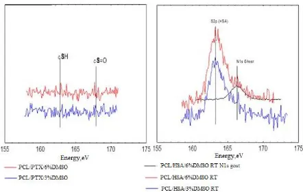
The concentration distribution of added components on the matrix surface was 314
evaluated by XPS (Figure 2). To evaluate the residual amounts of DMSO S2p XPS spectra of 315
sulfur were acquired. The use of S2p signals for spectroscopic analysis of PCL-HSA matrices 316
is rather complicated, since sulfur is a minor component of proteins. Fortunately, “organic” 317
(C-S-H) and sulfoxide (C-S=O) states of sulfur have substantially different S2p positions on 318
a binding energy scale. Indeed, the spectra of PCL-HSA samples have a distinct S2p peak at 319
163.3 eV attributed to protein sulfur due to both its binding energy value and the signal 320
intensity. At first glance, the smaller peak located at 166.3 eV could account for sulfur in 321
DMSO moieties. However, it definitely includes N1s a “ghost peak” resulting from 322
cross-contamination by AlKα radiation (ca. 1% in this case). The intensity of N1s ghost line 323
(black curve in Figure 2B) well matched the intensity of the peak 163.3 eV in S2p spectrum. 324
content and treatment regimes, suggesting that PTX release could not be caused by the 326
diffusion of DMSO from the matrices. 327
328
Figure 2. S2p XPS spectra of the samples PCL + PTX + DMSO (A) and PCL + DMSO +
329
HSA (B). 330
Table 3 shows that the HSA content of the surface layer slightly decreased inversely 331
proportionally to DMSO concentration, which may indicate that HSA is transported by the 332
HFIP flow during fiber drying. As shown earlier [25], incubation of matrices in physiological 333
solution leads to a reorganization of the surface layer and an increase in the HSA 334
concentration on the surface. 335
336
337
338
339
340
341
342
343
344
345
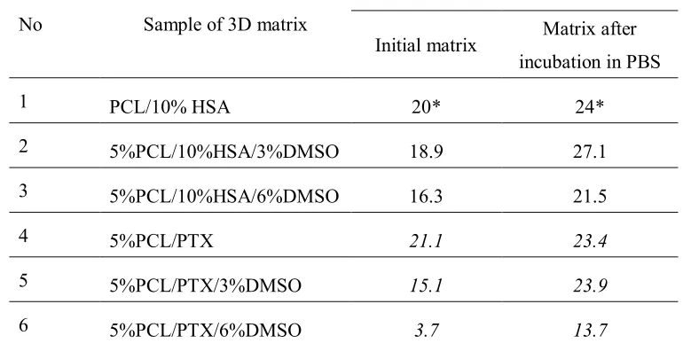
[image:11.595.94.536.135.416.2]Table 3. XPS data on HSA and PTX surface concentrations in electrospun 3D matrices 347
obtained from different PCL/HSA or PCL/PTX blends 348
No Sample of 3D matrix
Concentration of HSA or PTX, %
Initial matrix Matrix after
incubation in PBS
1 PCL/10% HSA 20* 24*
2 5%PCL/10%HSA/3%DMSO 18.9 27.1
3 5%PCL/10%HSA/6%DMSO 16.3 21.5
4 5%PCL/PTX 21.1 23.4
5 5%PCL/PTX/3%DMSO 15.1 23.9
6 5%PCL/PTX/6%DMSO 3.7 13.7
*According to (a study by) Chernonosova et al. 2017. [25]
349
According to XPS results, the PTX concentration in the surface layer of the 350
PCL-based 3D matrices also decreased inversely proportionally to DMSO concentration in 351
ES solution (Table 2). Only 3.7% of PTX was detected in the surface layer of 352
5%PCL/PTX/6%DMSO 3D matrices in contrast to 21% in the matrices from pure PCL. The 353
increase in the PTX concentration on the surface of electrospun fibers was previously 354
described for matrices prepared from PCL in dichloromethane [11]. The authors attributed 355
this finding to the effect of solvent drying during ES. 356
Similarly to HSA, PTX concentration in the surface layer increased after incubation 357
of the matrices in the physiological solution, which was especially noticeable in the 5% PCL/ 358
PTX/6% DMSO matrices made (10% PTX concentration increase). Apparently, wetting of 359
the matrices leads to a structural reorganization of the fiber surface, and low PTX solubility 360
in water [34] results in its accumulation on the matrix surface. Unfortunately, one is unable to 361
use XPS to measure concentrations of PTX and HSA simultaneously. Considering the ability 362
of HSA to bind PTX (in aqueous solution) and potential hydrophobic interactions between 363
PTX and HSA one can consider that HSA exposed at fiber surface can additionally retain 364
PTX,slowing down its release out of fibers. 365
The detection depth of XPS is no more than 10 nm. In a 500 nm fiber, the 10 nm thick 366
surface layer occupies approximately 8% of the total volume. Given that the percentage of 367
PTX in the matrices is no more than 0.01%, even if all PTX were to concentrate in this layer, 368
its concentration should not exceed 0.2%, as opposed to the 3.7-21% PTX concentration 369
according to XPS data. For the weight balance to equalize, the PTX layer should have a depth 370
[image:12.595.104.489.129.327.2]surface layer of the fibers, which interfaces with the external medium and facilitates PTX 372
release into the solution. 373
The porosity of matrices calculated from the matrix volume and the density of the 374
polymer composition varied in the range 77-80% and was not significantly different for 375
matrices prepared from different solutions. The porosity evaluated by SEM was 54% to 76%, 376
and the pore size varied from 5.7 to 0.97 µm. The matrices synthesized from DMSO 377
solutions were less uniform, in terms of not only fiber diameter, but also the pore size (Table 378
2, Figure 1). 379
No weight loss of the matrices was detected after drying, even though matrices made 380
of PCL with 10% HSA are known to release the protein into solution [25]. This loss could not 381
be detected by gravimetric methods under the conditions of the experiment (the loss is 382
0.2-0.3% of the matrix weight, provided that the matrix weight is no more than 5 mg, and the 383
weight of released HSA is only 10-15 µg). 384
Water absorption varied from 294% for the pure PCL matrices to 883% for 5% PCL/ 385
PTX/6%DMSO/HSA matrices. According to a previous study based on the Washburn’s 386
equation, the time required to fill nanopores is several microseconds [35], which means that 387
the observed differences in water absorption cannot be caused by incomplete hydration of the 388
matrices. The water absorption value is inversely proportional to the contact angle of 3D 389
matrices and the fiber diameter. In addition, HSA-containing matrices retain more water than 390
those without the protein, which is likely caused by the higher hydrophilicity of the 391
HSA-containing matrices and the hydration of HSA within the fibers. 392
The surface of PCL-based matrices without HSA was hydrophobic (Table 2), they 393
were poorly wetted, and lost almost all water after the first drying period (Figure 3) [35]. The 394
second drying period for these matrices was very short, which can indicate a rapid transport 395
of water from the internal volume of the matrices and lack of interaction between water and 396
matrix surface. 397
PCL/HSA matrices had contact angle below 90°, indicating hydrophilicity. Provided 398
that the density of PCL is 1.021 g/cm3, the matrix adsorbed no less than 589% of water 399
(weight percentage) but quickly lost it during the first drying period. The hydrophilic fiber 400
surface retains the water to a greater extent, therefore, explaining the longer second drying 401
period typical for these matrices. 402
PCL/HSA/DMSO matrices were more hydrophilic compared to those without HSA 403
and absorbed significantly more water (Table 3). Apparently, the mass transfer of water in 404
these matrices is determined by not only by the flow from the hydrostatic drop pressure 405
occurring due to filling of pores of different radii (as described by Laplace’s law) but also the 406
interaction of water with the fiber surface. Indeed, mass transfer may include 407
surface-diffusion flows, film formation, and the occurrence of disjoining pressure, which can 408
value (surfaces with ultrastructural disturbances are filled preferentially) [35]. Matrices with 410
HSA and DMSO exhibited pronounced first and second drying periods, with the latter lasting 411
longer and resulting in a higher water loss as compared to matrices without DMSO (Figure 412
3). Judging by this, the microstructure of such matrices has similar characteristics, although 413
matrices with 6% DMSO had a lower contact angle and were more thoroughly filled with 414
water. These matrices were also more heterogeneous in fiber diameter (Figure 1), consisted 415
of thinner fibers and had a more branched surface. 416
417
[image:14.595.122.435.232.442.2]418
Figure 3. Drying rate of 3D matrices. The data presented as means, error of the mean does
419
not exceed 7%. 420
3.3. PTX release from matrices 421
It is known that hydrophilic matrices have a lower capacity to adsorb proteins [36] 422
and induce inflammation and, therefore, have advantages over hydrophobic matrices as 423
materials for implants [37]. Introduction of HSA decreases the contact angle, thus making 424
matrices more hydrophilic (Table 2) and increasing their hemo- and biocompatibility [21, 425
22]. The introduction of 3% or 6% of DMSO in PCL matrices did not lead to a significant 426
change in the contact angle but affected matrix structure, fiber diameter, and water 427
absorption, thus effectively increasing the area of medium-matrix interface. The two-phase 428
nature of drying and high interface surface characteristic of the matrices with HSA and 429
DMSO compared to other 3D matrices allow one to hope that PTX can be released 430
effectively from such matrices and that its release kinetics would also follow a two-phase 431
profile. 432
As mentioned in “Materials and Methods”, PTX release from the matrices was 433
studied without (1) or with the replacement of the media (2), i.e., the solution was replaced by 434
bloodstream (medium replacement) and in the vascular wall (no or slow replacement of 436
medium). 437
It should be noted that mathematical modelling of the mechanisms of drug delivery 438
controlled by diffusion, osmosis, swelling/dissolution processes, etc is well-developed [38]. 439
The release of low-molecular-weight compounds (Rhodamine 610) from electrospun 440
matrices made of PCL [32] or bovine serum albumin (BSA) from PCL/BSA matrices [39] 441
was studied earlier. The delivery of rhodamine was shown to be limited by its diffusion from 442
fibers. The authors developed a theoretical model of the release and evaluated its parameters, 443
such as nanoporosity and desorption enthalpy. They showed that the release is saturable - 444
only a portion of rhodamine can be released, the precise amount depending on the fiber pore 445
structure. Diffusion of this part of the compound from the fibers took between two and our 446
days and the fibers no longer release rhodamine. Materials exhibiting this type of the release 447
are poor candidates for stent coatings. Moreover, the authors did not attempt to enhance the 448
bio- and hemocompatibity of the matrices and only studied the release of rhodamine and 449
protein molecules from synthetic polymers. 450
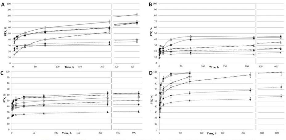
The kinetic curves of PTX release are presented in Figure 4. The release in PBS from 451
5%PCL/PTX and 5% PCL/PTX/10%HSA matrices appears to be similar to that described 452
earlier [32] with a saturation time of three days (Figure 4 A). However, some differences 453
were observed, which were probably caused by the low solubility of PTX (less than 0.3 mg/L 454
or 3.5 µМ in water). When incubated with medium replacement, PTX was released from the 455
fibers past the third day and for as long as up to 27 days, and the total amount released was 456
double the PTX release in PBS without medium replacement (Figure 4 B). 457
458
Figure 4. Kinetics of PTX release from matrices. (A) Incubation of 3D matrices with PBS
459
[image:15.595.81.545.499.726.2]replacement after each time point; (C) Incubation of 3D matrices with human plasma without 461
medium replacement; (D) Incubation of 3D matrices with human plasma with medium 462
replacement after each time point. 463
In a fiber PTX can be found both in the volume and on the surface: PTXtotal =
464
PTXvolume + PTXsurface. One can assume that without medium replacement, an equilibrium
465
between PTX on the surface and PTX in the solution is achieved during the first three days 466
(in PBS). Because of the low PTX solubility in water, the rate at which the equilibrium is 467
established is limited by its desorption from the matrix surface. In the case of medium 468
replacement, dissolved PTX is periodically removed, leading to additional desorption of 469
PTX from the fibers into the solution, thus increasing the amount of dissolved PTX over 470
time. Moreover, in HSA-containing matrices, the sorption/desorption on the fiber surface is 471
accompanied by the binding of PTX to HSA (Kа = 1.43×10⁴ M-1 [20]), which can retain PTX
472
both within and on the surface of the fibers. 473
During the incubation of matrices with plasma without replacement, the nature of the 474
release did not change but saturation was achieved in five–seven days (Figure 4 C) and more 475
PTX was released (55–60% vs 45%). When incubated with plasma replacement, PTX was 476
completely released from matrices in three days (Figure 4 D). Apparently, HSA in plasma 477
binds dissolved PTX, which prevents the resorption of PTX on the matrix surface. The 478
concentration of HSA-bound PTX can be evaluated by taking into account the following 479
factors: HSA concentration in plasma is ~1 mM; PTX concentration is ~0.82 µM; when 50% 480
of this compound is released from the matrix (MWPTX is 854, the matrix contains 0.36 µg, the
481
solution volume is 0.25 mL); association constant is Kа = 1.43×10⁴ M-1. Using material
482
balance equations, the concentration of the PTX-HSA complex is calculated as 0.77 µM. 483
Thus, under these conditions, 94% of released PTX is associated with HSA. It is likely that 484
other biomolecules in plasma can also be involved, e.g., lipids can interact with fat-soluble 485
PTX on the surface or even within the matrix. 486
Since incubation with plasma replacement increased the PTX release to 100%, PTX 487
diffusion rate within the fibers/matrix did not limit the rate of PTX release. It should be noted 488
that, according to SEM data, the fiber structure of these 3D matrices also did not change 489
during long term incubation and PTX release into the solution (Figure 1) that is, the 490
degradation or reorganization of the matrix structure is not associated with long-term PTX 491
release. 492
The results indicate that 5%PCL/PTX and 5%PCL/PTX/10%HSA matrices are not 493
suitable for the prolonged delivery of the drug because they do not facilitate the long time 494
two-phase kinetics of PTX release and the drug is rapidly released when matrix is in contact 495
with human plasma. To obtain 3D matrices, which are capable of prolonged PTX release, it is 496
retain PTX in the fiber during the solvent drying step and/or obtain the porous fibers, DMSO 498
was added to the electrospining solution because its nontoxic, has a high boiling point 499
(189°С), and dissolves PTX. In previous reports, the factor of matrix nanoporosity has been 500
theoretically explored [30]. The authors of this report used a similar solvent system for 501
electrospinning - a mixture of dimethylformamide (Tbp = 153°С) with dichloromethane (Tbp
502
= 40°С). It was shown that the addition of 3% DMSO in the electrospinning solution 503
significantly decreased the total PTX release into PBS (up to 25–35%) under conditions 504
without medium replacement (Figure 4 A). For matrices with 6% DMSO the PTX release 505
was slightly decreased, while almost no decrease of the total PTX release was observed in 506
medium replacement conditions (Figure 4 B). These data are consistent with XPS 507
demonstrating a decrease of PTX on the surface of 3D matrices electrospun from the 508
solutions with DMSO (Table 3). As in previous cases, the rate of PTX diffusion from the 509
fiber/matrix volume to its surface does not limit the rate of PTX transfer into the solution 510
since no change in the total release of PTX under the conditions with medium replacement 511
was detected. 512
In regards to PTX release into the plasma, the addition of 6% of DMSO slightly 513
decreased the release under the conditions with plasma replacement (Figure 4 D) but had no 514
effect on PTX release without replacement (Figure 4 C). It should be noted that the matrices 515
prepared from DMSO-containing solutions consist of thinner fibers as compared with the 516
other matrices. Moreover, 3D matrices produced from ES solutions with 6% of DMSO are 517
characterized by more hydrophobic surfaces, lower water adsorption, and lower amount of 518
PTX on the surface according to the XPS data as compared with the matrices prepared from 519
the solutions containing 3% DMSO. 520
Generally speaking the matrices prepared from solutions containing DMSO and HSA 521
are characterized by a slow release of PTX (Figures 4 C and 4 D). Matrices made from the 522
5%PCL/PTX/3%DMSO/10%HSA released ~30% and 60% of PTX in 28 days under the 523
conditions, both with and without medium replacement, respectively. The daily release of 524
PTX decreased from ~25% (day 1) to 0.05% (day 28) and from ~45% (day 1) to 0.26% (day 525
28) under the conditions, both with and without medium replacement, respectively. These 526
results indicate the effect of DMSO, which changes the matrix structure and the distributions 527
of both PTX and HSA in the fibers (Tables 2 and 3). 528
Thus, the composition of ES solution and outside medium significantly affects the 529
rate of the PTX release. The removal of dissolved PTX due to the medium replacement 530
and/or binding to HSA, both prevent its resorption and lead to the fast diffusion of PTX from 531
the fibers and its complete release from the matrix. Thus, desorption of PTX from fibers is 532
the rate-limiting stage of PTX release. The results for matrices produced from ES solution 533
with DMSO show that increased hydrophobicity of 3D matrices reduces desorption of PTX 534
effect. 3D matrices produced from solutions of PCL, HSA and DMSO in HFIP exhibited a 536
pronounced two-phase kinetics profile of PTX release into PBS or human plasma. The first 537
phase is the fast release due to desorption of PTX from the surface, the second stage is the 538
slow PTX release caused by its interaction with HSA located within the hydrophobic fibers. 539
Earlier, it was shown that rhodamine was only partly released into aqueous solutions 540
from electrospun fibers prepared from PCL solutions in 541
dimethylformamide/dichloromethane mixture, and a portion of rhodamine localized in the 542
solid polymer phase, is never released [32]. Our results demonstrate that PTX can completely 543
diffuse from the matrices prepared from PCL or PCL/HSA in HFIP with or without DMSO 544
when the matrices are incubated with the human plasma (Figure 4 D). According to the XPS 545
data (Table 2), a significant amount of PTX is exposed on the matrix surface, and the 546
incubation of matrices with aqueous solutions led to a release of PTX (Figure 4) and 547
reorganization of the surface layer, resulting in a further increase in the PTX concentration on 548
the matrix surface (Table 2). Apparently, the structure of the fibers prepared from HFIP 549
solutions and chemical properties of PTX allow this compound to be redistributed in the 550
fibers. In any case, the matrices capable of complete PTX release are optimal for facilitating 551
its delivery. 552
The data on structure of 3D matrices (Tables 2 and 3) are strongly correlate with 553
release of PTF from fibers. Actually, fibers able to accumulate PTX in their bulk and 554
swelling during incubation demonstrated slower PTX release kinetics. It is interesting to note 555
that water loss by matrices correlates with kinetics of PTX release (Figures 3 and 4). 556
Stretching of the matrices to the point of two-fold elongation did not affect the PTX 557
release. Both the nature of the release and the amount of released PTX per one unit of the 558
matrix weight remained unchanged. However, the elongation of the matrices led to plastic 559
deformation because of the small area of elastic deformation (7–10%), and the linear size of 560
the matrices increased to 125–185% after loading. The amount of PTX released from 561
elongated matrices was proportionally lower compared to untreated matrices. It is necessary 562
to take this into account whenoptimizing the cytostatic dose of the drug for stent coating. 563
The nature of PTX release from 3D matrices containing HSA and DMSO and 564
electrospun from HFIP solutions enables their use as coatings for vascular stents intended to 565
prevent restenosis and proliferation of cell in the vascular wall. The perivascular delivery of 566
PTX at concentrations from 20 to 230 µM under the conditions of internal pressure ensures 567
its efficient accumulation in the artery walls, with predominant localization in the adventitia 568
area [40]. According to some authors, the diffusion coefficient for PTX in arterial wall varies 569
from 1×10⁻⁸ cm2/s to 4.87×10⁻⁶ cm2/s [41]. It is interesting to note that the diffusion 570
coefficient for HSA (the main transporter of PTX) in the aortal wall (evaluated without 571
regard to potential binding in the adventitia) is 1.06×10⁻⁸ cm2/s [42] and the protein is 572
[43]. In addition, it has been shown that elastin itself binds PTX and can promote its retention 574
in the artery wall [44]. The accumulation of PTX in this layer can be mediated by PTX 575
binding to both HSA and elastin. The toxic PTX concentration against smooth muscle 576
myocytes is ~10 nM [45]. Providing that the matrix contains 0.46 µg/cm2 of PTX and 1% of
577
it is released daily, the PTX concentration in the wall will be equal to or higher than its toxic 578
concentration. One should take into account the initial accumulation of PTX in the wall, its 579
low solubility, and the binding with the components of the extracellular matrix. Thus, the 580
coating of bare-metal stents with scaffolds electrospun from the solutions of PCL with HSA 581
and DMSO and containing 0.46 µg/cm2 of PTX can be toxic against vascular wall myocytes 582
for at least three months. Herewith, the PTX dose, which is released during the first days after 583
the stent implantation, will make it possible to eliminate the proliferation of activated cells, 584
and high PTX concentration will compensate for its diffusion through the partially destroyed 585
artery wall immediately after implantation. Furthermore, the data on the complete PTX 586
release from the matrices produced from the HFIP solutions of PCL allows one to hope for an 587
even more prolonged release of PTX from the fibers. It should also be noted that the change 588
in the structure of the matrices during incubation, their shrinkage, and fiber aggregation, 589
resulting in the reduction of the phase interface, could prolong the PTX release from the 590
fibers and thus assist the cytotoxic effect of drugs introduced in such matrices. 591
4. Conclusions
592
The physicochemical properties of electrospun matrices prepared from the solutions 593
of PCL with PTX in HFIP and their blends with HSA and DMSO were studied. It was shown 594
that 3D matrices produced from a HFIP solution of PCL with PTX, HSA and DMSO are the 595
most suitable to be used as coatings for bare-metal stents because they are not expected to 596
exert any significant additional stress on the stent beams, exhibit long time two-phase 597
kinetics of PTX release, and thus are expected to be able to maintain a cytotoxic PTX 598
concentration in the vascular wall for at least three months. It was shown that PTX can be 599
completely released from these matrices without fiber degradation. The use of plasma as the 600
external medium accelerated PTX release, while two-fold elongation of 3D matrices did not 601
interfere with the kinetics of the release. Thus, PCL-based 3D matrices containing HSA, PTX 602
and DMSO can be used for the production of coated vascular stents with prolong delivery of 603
PTX. 604
Author Contributions: 605
The authors wish it to be known, that in their opinion, the first two authors should be regarded 606
as joint First Authors. 607
The authors make the following individual contribution: K. A. Kuznetsov – investigation, 3D 608
matrix production and PTX release study; A. O. Stepanova – investigation, matrix 609
characterization and PTX release study; R. I. Kvon – investigation, XPS study; T. E.L. 610
formal analysis; V. S. Chernonosova – investigation, visualization; Ivan A. Zaporozhchenko 612
– investigation, validation; M. V. Kharkova – methodology; I. V. Romanova – investigation, 613
PTX labeling; A. A. Karpenko – resources, methodology; P. P. Laktionov – supervision, 614
project administration, funding acquisition, writing. 615
Funding: 616
This research was funded by Russian Scientific Foundation, grant number 18-15-00080. 617
Conflicts of Interest: 618
The authors declare no conflict of interest. The funders had no role in the design of the study; 619
in the collection, analyses, or interpretation of data; in the writing of the manuscript, or in the 620
decision to publish the results. 621
References
622
1. Sill, T.J.; von Recum, H.A. Electrospinning: applications in drug delivery and tissue 623
engineering. Biomaterials2008, 29, 1989-2006. 624
2. Brough, C.; Williams, R.O. Amorphous solid dispersions and nano-crystal 625
technologies for poorly water-soluble drug delivery. Int. J. Pharm.2013, 453, 157-166. 626
3. Cui, W.; Li, X.; Zhu, X.; Yu, G.; Zhou, Sh.; Weng J. Investigation of drug release and 627
matrix degradation of electrospun poly(DL-lactide) fibers with paracetanol inoculation. 628
Biomacromolecules 2006, 7, 1623–1629.
629
4. Seitz, J.M.; Durisin, M.; Goldman, J.; Drelich, J.W. Recent advances in biodegradable 630
metals for medical sutures: a critical review. Adv. Healthcare Mater. 2015, 4, 1915– 631
1936. DOI: 10.1002/adhm.201500189. 632
5. Yang, Y.; Li, X.; Cui, W.; Zhou, Sh.; Tan, R.; Wang, Ch. Structural stability and 633
release profiles of proteins from core-shell poly (DL-lactide) ultrafine fibers prepared by 634
emulsion electrospinning. J. Biomed. Mater. Res. A2008, 86, 374-385. 635
6. Lo, H.; Ponticiello, M.S.; Leong, K.W. Fabrication of controlled release biodegradable 636
foams by phase separation. Tissue Eng. 1995, 1, 15–28 637
7. Okuda, T.; Tominag, K.; Kidoak, S. Time-programmed dual release formulation by 638
multilayered drug-loaded nanofiber meshes. J. Control. Release2010, 143, 258-264. 639
8. Rosic, R.; Pelipenko, J.; Kristl, J.; Kocbek, P.; Baumgartner, S. Properties: engineering 640
and applications of polymeric nanofibers: current research and future advances. Chem. 641
Biochem. Eng. Q.2012, 26, 417–425.
642
9. Khadka, D.B.; Haynie, D.T. Protein- and peptide-based electrospun nanofibers in 643
medical biomaterials. Nanomed. Nanotechnol. Biol. Med. 2012, 8, 1242–1262. 644
10. Bhardwaj, N.; Kundu, S.C. Electrospinning: a fascinating fiber fabrication technique. 645
Biotechnol. Adv. 2010, 28, 325–347.
646
11. Zhu, Y.; Hu, Ch.; Li, B.; Yang, H.; Cheng, Y.; Cui, W. A highly flexible 647
paclitaxel-loaded poly(e-caprolactone) electrospun fibrous-membrane-covered stent for 648
12. Tefft, B.J.; Uthamaraj, S.; Harburnc, J.J.; Hlinomazd, O.; Lermana, A.; 650
Dragomir-Daescue, D.; Sandhua, G.S. Magnetizable stent-grafts enable endothelial cell 651
capture. J. Magn. Magn. Mater.2017, 427, 100–104. 652
13. Papafaklisa, M.I.; Chatzizisis, Y.S.; Naka, K.K.; Giannoglou, G.D.; Michalis, L.K. 653
Drug-eluting stent restenosis: effect of drug type, release kinetics, hemodynamicsand 654
coating strategy. Pharmacol. Therapeut.2012, 134, 43-53. 655
14. Dangas, G.D.; Claessen, B.E.; Caixeta, A.; Sanidas, E.A.; Mintz, G.S.; Mehran, R. 656
In-stent restenosis in the drug-eluting stent era. J. Am. Coll. Cardiol. 2010, 56, 657
1897-1907. 658
15. Radke, P.W.; Kaiser, A.; Frost, C.; Sigwar, U. Outcome after treatment of coronary 659
in-stent restenosis: results from a systematic review using meta-analysis techniques. Eur. 660
Heart J.2003, 24, 266–273.
661
16. Park, S.J.; Shim, W.H.; Ho, D.S.; Raizner, A.E.; Park, S.W.; Hong, M.K.; Lee, 662
Ch.W.; Choi, D.; Jang, Y.; Lam, R.; Weissman, N.J.; Mintz, G.S. A paclitaxel-eluting 663
stent for the prevention of coronary restenosis. N. Engl. J. Med.2003, 348, 1537-1545. 664
17. Aoki, J.; Kirtane, A.; Martin, S.M.; Leon, B.; Dangas, G. Coronary artery aneurysms 665
after drug-eluting stent implantation. JACC Cardiovasc. Interv.2008, 1, 14-21. 666
18. Müller-Hülsbeck, S. Eluvia™ peripheral stent system for the treatment of peripheral 667
lesions above the knee. Expert. Opin. Drug. Deliv. 2016, 13, 1639-1644. 668
19. Schofer, J.; Musiałek, P.; Bijuklic, K.; Kolvenbach, R.; Trystula, M.; Siudak, Z.; 669
Sievert, H. A prospective, multicenter study of a novel mesh-covered carotid stent: the 670
CGuard CARENET trial (carotid embolic protection using MicroNet). JACC 671
Cardiovasc. Interv.2015, 8, 1229-1234.
672
20. Purcell, M.; Neault, J.F.; Tajmir-Riahi, H.A. Interaction of taxol with human serum 673
albumin. Biochim Biophys Acta.2000, 1478, 61-68. 674
21. Shen, M.; Martinson, L.; Wagner, M.S.; Castner, D.G.; Ratner, B.D.; Horbett, Th.A. 675
PEO-like plasma polymerized tetraglyme surface interactions with leukocytes and 676
proteins: in vitro and in vivo studies. J. Biomater. Sci. Polym. Ed. 2002, 13, 367-390. 677
22. Denizli, F.K.; Guven, O. Competitive adsorption of blood proteins on 678
gamma-irradiated-polycarbonate films. J. Biomater. Sci. Polym. Ed. 2002, 13,127-139 679
23. Sidorov, V.N.; Polak, Yu.V.; Laktionov, P.P.; Roshcke, V.V.; Kist, A.G. Method of 680
production of tritium labeled organic compounds and the device for its implementation. 681
Patent SU 1823961 А3, priority from 18.01.1991. 682
24. Cardiovascular Implants-Tubular Vacuum Prostheses. International Standard 683
ISO/FDIS 7198:1998. 684
25. Chernonosova, V.S.; Kvon, R.I.; Stepanova, A.O.; Larichev, Y.V.; Karpenko, A.A.; 685
PCL fibers: structure, release, and exposure on fiber surface. Polym. Adv. Technol. 2017, 687
28, 819-827. 688
26. Moulder, J.F.; Stickle, W.F.; Sobol, P.E.; Bomben, K.D. Handbook of X-Ray 689
photoelectron spectroscopy. Perkin-Elmer, Eden Prairie, 1992. 690
27. Karimi, A.; Navid, M.; Shojaeic, A.; Faghihi, Sh. Measurement of the uniaxial 691
mechanical properties of healthy and atherosclerotic human coronary arteries. Mater Sci 692
Eng C Mater Biol Appl.2013, 33, 2550-2554.
693
28. Goladkina, А.А.; Kirilova, I.V.; Shychkina, О.А.; Maslaykova, G.N.; Ostrovskii, 694
N.V.; Chelnokova, N.О. Finite-element modeling of ischemic heart disease from the 695
picture of morphofunctional changes of arteries and the heart muscle of the human. 696
Russian Journal of Biomechanics.2011, 15, 33–46.
697
29. Megelski, S.; Stephens, J.S.; Chase, D.B.; Rabolt, J.F. Micro- and nanostructured 698
surface morphology on electrospun polymer fibers. Macromolecules 2002, 35, 699
8456-8466. 700
30. Casper, Ch.L.; Stephens, J.S.; Tassi, N.G.; Chase, D.B.; Rabolt, J.F. Controlling 701
surface morphology of electrospun polystyrene fibers: effect of humidity and molecular 702
weight in the electrospinning process. Macromolecules2004, 37, 573-578. 703
31. Katsogiannis, K.A.G.; Vladisavljevic´, G.T.; Georgiadou, S. Porous electrospun 704
polycaprolactone fibers: effect of process parameters. J Polymer Sci Part B: Polymer 705
Physics.2016, 54, 1878-1888.
706
32. Srikar, R.; Yarin, A.L.; Megaridis, C.M.; Bazilevsky, A.V.; Kelley, E. 707
Desorption-limited mechanism of release from polymer nanofibers. Langmuir.2008, 24, 708
965–974. 709
33.Abouelmagd, S.A.; Sun, B.; Chang, A.C.; Ku, Y.J.; Yeo, Y. Release kinetics study of 710
poorly water-soluble drugs from nanoparticles: are we doing it right? Mol. 711
Pharmaceutics. 2015, 12, 997–1003. DOI: 10.1021/mp500817h.
712
34. Pisani, S.; Dorati, R.; Conti, B.; Modena, T.; Bruni, G.; Gentaa, I. Design of 713
copolymer PLA-PCL electrospun matrix for biomedical applications. React Funct 714
Polym.2018, 124, 77-89.
715
35. Parmon, V.N. Modern approaches to the study and description of the processes of 716
drying porous bodies. 2001, Novosibirsk, Siberian Branch of the Russian Academy of 717
Sciences, 300 p. 718
36. Chernonosova, V.S.; Gostev, A.A.; Gao, Y.; Chesalov, Y. A.; Shutov, A.V.; 719
Pokushalov, E.A.; Karpenko, A.A.; Laktionov, P.P. Mechanical properties and biological 720
behavior of 3D matrices produced by electrospinning from protein-enriched 721
polyurethane. BioMed Research International. 2018, 2018, Article ID 1380606. 722
37. Yasukawa, T.; Ogura, Y.; Sakurai, E.; Tabata, Y.; Kimura, H. Intraocular sustained 723
drug delivery using implantable polymeric devices. Adv Drug Deliv Rev2005, 57, 2033– 724
38. Peppas, N.A.; Narasimhan, B. Mathematical models in drug delivery: How modeling 726
has shaped the way we design new drug delivery systems. J Control Release.2014, 190, 727
75-81. 728
39. Gandhi, M.; Srikar, R.; Yarin, A.L.; Megaridis, C.M.; Gemeinhart, R.A. Mechanistic 729
examination of protein release from polymer nanofibers. Mol. Pharmaceutics. 2009, 6, 730
641–647. 731
40. Creel, Ch.J.; Lovich, M.A.; Edelman, E.R. Arterial paclitaxel distribution and 732
deposition. Circulation Research.2000, 28, 879-884. 733
41. Levin, A.D.; Vukmirovic, N.; Hwang, Ch.W.; Edelman, E.R. Specific binding to 734
intracellular proteins determines arterial transport properties for rapamycin and 735
paclitaxel. PNAS 2004, 101, 9463-9467. 736
42. Baldwin, A.L.; Secomb, T.W.; Simon, B.R. Convection and diffusion of albumin 737
through artery walls: Implications for local drug delivery. In American Society of 738
Mechanical Engineers, Bioengineering Division.1997, 35, 93-94.
739
43. Goriely, A.R.; Baldwin, A.L.; Secom, T.W. Transient diffusion of albumin in aortic 740
walls: effects of binding to medial elastin layers. Am J Physiol Heart Circ Physiol.2007, 741
292, 2195–2201. 742
44. Sirianni, R.W.; Kremer, J.; Guler, I.; Chen, Y.L.; Keeley, F.W.; Saltzman, W.M. 743
Effect of extracellular matrix elements on the transport of paclitaxel through an arterial 744
wall tissue mimic. Biomacromolecules.2008, 10, 2792-2798. 745
45. Axel, D.I.; Kunert, W.; Göggelmann, C.; Oberhoff, M.; Herdeg, C.; Küttner, A.; 746
Wild, D.H.; Brehm, B.R.; Riessen, R.; Köveker, G.; Karsch, K.R. Paclitaxel inhibits 747
arterial smooth muscle cell proliferation and migration in vitro and in vivo using local 748
drug delivery. Circulation1997, 15, 636-645. 749