© 2019, IRJET | Impact Factor value: 7.211 | ISO 9001:2008 Certified Journal | Page 3442
Seismic Analysis and Retrofitting of Reinforced Concrete Building in
Indian Seismic Zone V
Anant Vats
1, Ankit Kumar Singh
2, Mr. Ashuvendra Singh
31
Under Graduate Student (B.Tech), PH-9472578694
2Under Graduate Student (B.Tech), PH-8084562885
3
Assistant Professor PH-8003780071
---***---Abstract -
Earthquake is one of major natural disaster inwhich many structures damage and collapse due to unacceptable or improper design against seismic motion. Earthquake also affects the economy of the nation and growth rate of the country, so essential proper measures of prevention must be developed for the betterment of the citizens and nation. The government and some other NGOs are also working in the field to create awareness for the seismic designing of new construction building especially in seismic susceptible areas but they are not considering the seismic resistance of the old buildings as it should be considered. The main objective of this project is to protect the new as well as the old buildings by designing it as earthquake resistant structure. Retrofitting is the procedure of improvement that enables the old structure to resist the force of consideration where Seismic Retrofitting is the improvement over the old structures that enables the structure to resist seismic action. There are many concepts for retrofit design of a building as earthquake resistant structure; the concept used in this project is base isolation. The best part of the Base isolation is that it can be implemented on both new as well as the old buildings. There are many types of base isolation systems too but we used lead rubber bearing (LRB) as base isolation system in this project because LRB is most commonly used as isolation system for buildings and bridges. We are also looking for creating awareness among the Engineers and the readers for such existing retrofitting techniques from side to side comparison between retrofitted buildings with fixed based simple frame building.
Key Words: E-TABS, Retrofitting, Base Isolation, Lead Rubber Bearing (LRB), Time History analysis, Response Spectrum Analysis, Seismic Zone V.
1.
INTRODUCTION
The Earthquake is natural calamity which is caused when the stress is produced on lithosphere due to collision between the two or more tectonic plates. When this stress is higher enough, the lithosphere breaks or shifts. The collision between plates may be of two types one is inter-plate (on the boundary of the tectonic plates) and other is intra-plate (anywhere over the tectonic plate). It should be noted that most of the earthquakes occurred in India near Himalayan region are inter-plate earthquakes and earthquakes
occurred near Peninsular region of India are intra-plate earthquakes so India should not neglect the seismic action.
India is one of the very sensitive countries around the world according to the seismic point of view. Even the current location of India ad formation of Himalaya and other such mountain ranges are the result of the Continental drift (shown in Fig 1.1).
[image:1.595.308.566.436.740.2]India lies in the north-western end of the Indo-Australian Plate, which includes India, Australia, a major portion of the Indian Ocean and other smaller countries like Bangladesh, Bhuttan, Nepal, Srilanka, Myanmar, Thailand, and Pakistan etc. This plate is colliding against the huge Eurasian Plate from millions of years and going under the Eurasian Plate, this process of one tectonic plate getting underneath other is called subduction in scientific world (shown in the Fig 1.2).
© 2019, IRJET | Impact Factor value: 7.211 | ISO 9001:2008 Certified Journal | Page 3443
Fig -1.2: Map showing collision between different Plates inIndia
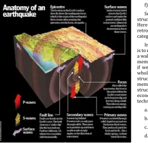
Fig -1.3: Anatomy of earthquake
As the Tectonic plates are resting over the molten Lava, so it is notice that during any seismic action high amount of energy is released from fault, either in the form of heat or seismic waves. These seismic waves emit from focus (starting place) and shake the ground. The point precisely above the focus on the earth’s surface is called the epicentre; observe the first seismic wave attack. The Fig 1.3 below shows the anatomy of the earthquake.
There are two methods to make the structure seismic resistant, one is to design the building as seismic resistant building in the starting the second is to retrofit the building. Retrofitting is the procedure of improvement that enables the old structure to resist the force of consideration, where Seismic Retrofitting is the improvement technique over the old structures that enables the structure to resist seismic action. The best part of the Base isolation is that it can be implemented on both new as well as old structures.
1.1 INTRODUCTION TO RETROFITTING
Retrofitting is the technique of improvement that enables the old structure to resist the force of consideration. On behalf of considerable force retrofitting can be classified as:
a) Seismic retrofitting b) Flood retrofitting c) Wind retrofitting d) Cyclonic retrofitting e) Snow retrofitting. f) Energy retrofitting
Seismic Retrofitting is the improvement over the old structures that enable the structure to resist seismic action. Here our main consideration is seismic retrofitting. Seismic retrofitting techniques are mainly classified into two categories: - Local techniques and Global techniques.
In Local techniques, the main focus of the seismic retrofit is to retrofit a particular member like: a beam or a column or a wall or stair case or foundation and give treatment for that member only. It is supposed in local retrofit technique is that if we retrofit that particular member which is weak; the whole structure will get safe. It is supposed that whole structure is good enough to carry load except that particular member so if we just treat that particular member the structure will be secured, this concept makes this technique economical comparatively. Some of the mainly used local techniques are as listed below:-
a. Jacketing of Beam b. Jacketing of Column
[image:2.595.37.330.463.746.2]© 2019, IRJET | Impact Factor value: 7.211 | ISO 9001:2008 Certified Journal | Page 3444
g. Underpinningh. Grouting
i. FRP of particular beam or column
In Global techniques, the main focus of the seismic retrofit is to retrofit the whole structure as the one. Global techniques consider the whole structure and consider the change of strength in whole structure due to change in a particular member. This technique is comparatively not economical but is safer. In practical if we make a change in any particular member the other members also get affected so either their strength increased or decreased. If it increases it’s not a problem but if in case it decreases the structure would be badly affected and the structure would be failed. The mainly used Global techniques are as listed below:-
a. Adding Shear wall b. Adding Infill wall c. Wall thickening d. Mass Damper e. Mass reduction
f. Fiber Reinforced Polymer (FRP) g. Equivalent load pendulum h. Base Isolation
The best part of the Base isolation is that it can be implemented on both new as well as old structures. Base isolation can also implemented in other infrastructures like: - bridge, nuclear power plant, water storage tanks and dams which will help the country to reduce the losses of life and economy due to seismic hazard.
Finally, complete content and organizational editing before formatting. Please take note of the following items when proofreading spelling and grammar:
1.2 INTRODUCTION TO BASE ISOLATION SYSTEMS
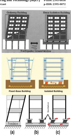
[image:3.595.302.580.55.587.2]Seismic isolation also known as base isolation is one of the best earthquake resistant design concept in which a building is decoupled from the earthquake ground motion or seismic waves. In base isolation the base of the structure is isolated using isolators (normally bearing isolators) which help in decoupling (it should be notice that the structures are generally failed due to couple formation during seismic action). When a building is decoupled from ground motion it significantly reduces response in the structure which would have affected building if it is fixed base. Base isolation decouples the building from ground motion by decreasing the fundamental frequency when compared to fix based building. This concept of base isolation also makes to remaining building behave elastic during an earthquake. Base isolation concept is also useful in other infrastructures like bridges, nuclear power plants and liquid storage tanks etc.
Fig - 1.4: Base isolation Concept (Structure with and without base isolation)
© 2019, IRJET | Impact Factor value: 7.211 | ISO 9001:2008 Certified Journal | Page 3445
the acceleration is basically reduced. It is most commonlyused concept of seismic designing where heavy weight dampers are used. Base isolation concept basically came from the bridge designing. The study of concept of rubber isolator bearings came into existence in 1976 and was studied over a 5 storied 3 bay 40 ton model which was selected for the first time in 1978.
Base isolators are basically a bearing mainly made up of rubber. Rubber provides cushion effect which help the structure to reduce the acceleration. Traditionally it was expected that structure would be fail due to horizontal acceleration only so the seismic designing was also based over that concept. Now days it is noticed that the seismic waves also travel in vertical direction so the structure also get fail due to vertical acceleration too. The concept of base isolator considers both the horizontal acceleration as well as vertical acceleration. The base isolator basically provides cushion effect and decouples the structure, it generates the hinge effect (it should be noted that the moment at hinge is always zero).
1.2.1 TYPES BASE ISOLATION SYSTEMS
The main types of base isolator system bearigs are: 1) Lead Rubber Bearings
2) High Damping Rubber Bearings 3) Elastomeric Rubber Bearings 4) Sliding Bearing
(a)Flat slider Bearings
(b) Curved slider or Pendulum Bearings 5) Roller and Ball Bearings
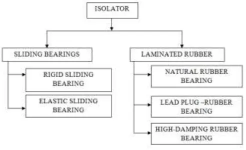
[image:4.595.45.291.548.698.2]Base isolation is the classified as shown in fig 1.5. We used Lead Rubber Bearings (LRB) for our experimental work.
Fig -1.5: Types of Isolator
1.2.1.1 Introduction of Lead Rubber Bearings (LRB)
Lead Rubber Bearings (LRB) are the bearings formed of horizontal layers of synthetic or natural rubber in thin layers
bound between steel plates and containing lead core. The components of the LRB are lead plug, endplates, steel shims and rubber layers. The steel shims provide vertical stiffness to the LRB and layers of rubber provide lateral flexibility or horizontal stiffness. These bearings are capable of supporting high vertical loads with very small deformations. These bearings are flexible under lateral loads. Steel plates prevent the rubber layers from bulging. Lead core of the LRB gives extra stiffness to the isolators and it also provides damping to the system. Lead cores are provided to increase damping capacity as plain elastomeric bearings does not provide significant damping. They are usually soft in horizontal direction and hard in vertical direction. LRB was first invented in 1975 in New-Zealand.
Companies like Dynamic Isolation Systems (DIS) and Bridgestone design and manufacture isolators according to the requirements of a client. LRB has the properties of both damper and isolator, lead plug’s plastic deformation makes LRB to absorb energy from vibration hence has property of damper and it has a flexibility property to deflect seismic waves hence act also as isolator.
The LRB has mainly these functions as listed below:-
Due to its property vertical stiffness functions as load supporter
Provide elasticity in horizontal direction due to the property of horizontal stiffness.
It has energy restoring capability
As it has lead core it provides damping to the structure by deforming plastically.
It reduces ground acceleration of a structure by increasing the time period of vibration of the structure.
It can be easily installed since no separate damper is required in case of LRB.
It has low maintenance requirement when compared to other types of isolators.
Some famous structures in India with base isolation system are listed below:
World bank, Delhi installed base isolator in 1998 Bhuj hospital, Bhuj (Gujarat) installed base isolator
in 2003
Dwarka hospital, Delhi installed base isolator in 2006
GTB Hospital, Delhi installed base isolator in 2008 Police Bhawan (Head quarter of Police), Patna (Bihar) installed base isolator in 2016-17 over a new construction
2. Ojective of the Project
© 2019, IRJET | Impact Factor value: 7.211 | ISO 9001:2008 Certified Journal | Page 3446
analysis method is used for analysis purpose using EL Centroearthquake data. The results were compared for Story drifts, Base shear, Story shear, and Mode shapes.
The objective of the project is as explained below:-
i. The G+8 storey RC bare frame is isolated using Lead rubber bearing (LRB) to reduce the story drifts when compared with conventional building having same condition which will help in the field of earthquake resistant structure. ii. To increase the displacement in all stories including
bottom stories of the base isolated structure when compared to conventional structure when analyzed by time history analysis. iii. To decrease the story drift and the base shear of a
base isolated structure when compared with fixed base structure.
iv. To design the Lead rubber bearing by using the data from E-TABS and to study the effectiveness of providing Lead rubber bearing (LRB) in the building.
v. To know the method of time history & response spectrum analysis using E-TABS and to get knowledge about the base isolation systems.
3. Methodology
i. The software used for analysis of a structure is E-TABS v 17.0.1.
ii. The dynamic analysis is carried for structural analysis
iii. The codes used are IS 1893 (PART I) 2016, UBC 1997, UBC Isolated 1997, IS 875 (PART 1, 2 and 5 for dead load, live load ad comination load respectively).
iv. There are many types of dynamic analysis in this project Time- History Analysis using EL Centro 1940 earthquake data was mainly done as the IS code suggest Response Spectrum analysis oly over the 30m hight buildings.
v. The building is modeled first then the loads are applied as per code provisions of IS 875 (PART I and II) Reaffirmed in 2008 for live and dead load
vi. For Time- History Analysis EL Centro 1940 earth-quake data is used
vii. After the analysis of a fixed base structure is performed the maximum axial load is noted from support reaction results for both interal and external supports.
viii.Then once axial load is noted the Lead core rubber bearing (LRB) is designed for both internal columns as well as external column separately on behalf of the maximum axial load.
ix. Then Properties of Lead core rubber bearing are calculated
x. Then these properties are used as link properties for base isolation structure in E-TABS.
xi. Then the Base Isolation Structure is analyzed for similar condition ut differet support property. xii. Then results are tabulated, compared and discussed
4. MODELING AND ANALYSIS
4.1 Time- History Analysis
Time- History Analysis is an analytical method that is
based over the past earthquake data that is history
data in regard with ground motion. In this method of
analysis the structure is subjected to the past
earthquake. The past earthquake data is inserted in the
software and the waves are generated for particular
time duration. Time history data is ploted on the graph
between acceleration and time. With the help of Time-
History Analysis various graph and tabular values can
be obtained even we can also check out the response
spectrum of the building. A response spectrum is a
curve which is plotted between maximum response of
single degree of freedom system which is subjected to a
specified seismic motion and its frequency (or time
period). This spectra helps in obtaining peak structural
responses (only when linear), it is also possible to find
lateral forces developed in a building due to an
earthquake, hence used for design of earthquake
resistant structures.
Procedure for using Time- History Analysis method of
analysis in ETABS.
Define Time history functions
Define mass source (Lumped mass)
Define load case (use time history to create
load case as per requirement) define load type
as acceleration.
Run analysis for fixed base first.
Then define LRB and apply the property.
For UBC spectra assign seismic coefficients Ca
and Cv
Assign damping ratio
Select type of model combination
Next step select type of directional
combination
To input time history data calculate scale factor
from following formula
© 2019, IRJET | Impact Factor value: 7.211 | ISO 9001:2008 Certified Journal | Page 3447
R= Response reduction factor In next step run the analysis and get result
Description and Modeling of Building
Software used for analysis is ETABS v 17.0.1 Units used are ‘KN-m’
Code provisions as per UBC 1997 and IS 1893 (Part 1) 2016 and UBC Isolated 1997
Type of analysis performed is Time history analysis.
Building Details:
Structure: RCC (SMRF)
Structure Type: Plan Irregular structure Plan Dimension: 25.5m×16m
Height of Building: G+8 (27.432m) Height of Each Storey: 3.048 m (10 feet) Building Type: residential
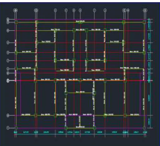
[image:6.595.307.568.162.429.2] Mumpty and Lift is over the roof
Fig -4.1: Structural plan of ground floor of building
Material Properties
Grade of Concrete: M30 (For Beams and column) M25 (For Slab and shear wall in lift area)
Grade of Steel: Fe415
Section Properties
Slab Thickness: 150mm Wall thickness: 230mm
Beam and columns have different dimesions shown in fig 1.6 and 1.7
Gravity Load
Dead Load: Column, Beam, Slab (Default Values) Live Load for Floors: 4.0 kN/m2
Live Load for Roof: 2.0 kN/m2 Floor Finish: 1.0 kN/m2
[image:6.595.38.295.351.585.2] Wall Load: thickness × density × height = 0.23×18×2.75= 11.385 kN/m Parapet Load: = 0.23×18×1 = 4.14 kN/m
Fig -4.2: Structural plan of first floor to 7th floor of building
Lateral Load for Response Spectrum Analysis (according to UBC 1997)
Seismic Zone Factor (Z) – Zone 3 Soil Profile Type - Sc
Seismic Coefficient Ca - 0.36 Seismic Coefficient Cv (CVD) - 0.54 Importance Factor (I) – 1.25
Response Reduction Factor (R) – 8.5(For SMRF) Seismic Source Type – B
Near Source Factor Na – 1 Near Source Factor Nv – 1
Damping coefficient (βD or βM) – 1
Damping (βeff) – 5% (for Concrete structure)
DESCRIPTION OF MODELS
Model 1: Time- History Analysis with Fixed Base Model 2: Time- History Analysis with Lead Rubber
© 2019, IRJET | Impact Factor value: 7.211 | ISO 9001:2008 Certified Journal | Page 3448
5. DESIGN OF BASE ISOLATOR (LRB) FORINTERNAL AND EXTERNAL COLUMNS
The type of base isolator used for analysis is lead rubber bearing isolator, to get the properties of isolator its design is carried out as shown below.
Note down the maximum support reaction (W) After the analysis of Model 1 the maximum support
reaction is noted
Display>show-tables>analysis result>reactions>support reactions
Tabulate the support reaction result in excel sheet and get the maximum support reaction
Max support reaction (W) for external column = 10015 kN
Max support reaction (W) for internal column = 11636 kN
Design Formulas for LRB calculations:-
1.
2.
= 7492.29
= 6448.54
3.
= 264.94
= 228.03
4. Force at design displacement of characteristics strength,
5. Pre yield in rubber,
6. Post yielding stiffness to pre yield stiffness ratio (n) for rubber,
7. Yield displacement,
= 0.003177 ≈ 0.0032
=0.003177 ≈ 0.0032
8. Recalculation of force Q to ,
= 199.32
= 171.55
9. Area of lead plug,
10. Dia of Lead plug
0.5037
6 m ≈ 503.76 mm
0.4674
m ≈ 467.4 mm
11. Recalculation of rubber stiffness
© 2019, IRJET | Impact Factor value: 7.211 | ISO 9001:2008 Certified Journal | Page 3449
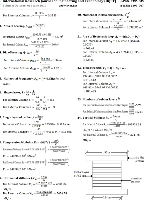
13. Area of bearing,14. Dia of bearing,
1.96 m
1.82 m
15. Horizontal Frequency, for both cases
16. Shape factor, S =
17. Single layer of rubber, t =
18. Compression Modulus, Ec )
kN/
kN/
19. Horizontal stiffness, (
kN/m
kN/m
20. Moment of inertia circulation, I=
21. Area of Hysteresis loop,
= 262.41
= 225.86
22. Yield strength,
= 219.512
= 188.435
23. Numbers of rubber layers
=5.70
= 6.14
24. Vertical Stiffness
= 192934.24 kN/m = 1929.35 MN/m
[image:8.595.62.554.52.741.2]= 2241.01 MN/m
© 2019, IRJET | Impact Factor value: 7.211 | ISO 9001:2008 Certified Journal | Page 3450
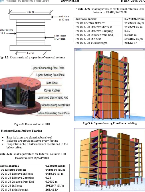
Fig -5.2: Cross sectional properties of external columnFig -5.3: Cross section of LRB
5.1 Placing of Lead Rubber Bearing
Base isolators are placed at base level Isolators are provided above every footing Properties of LRB Calculated are mentioned in the
below tables
Table -5.1: Final input values for External columns LRB Isolator in ETABS/SAP2000
Rotational Inertia1 0.538586 kN/m
For U1 Effective Stiffness 6448540 kN/m For U2 & U3 Effective Stiffness 6448.54 kN-m For U2 & U3 Effective Damping 0.05
For U2 & U3 Distance from End-J 0.0032 m For U2 & U3 Stiffness 59420.7 kN/m For U2 & U3 Yield Strength 262.41 kN
Table -5.2: Final input values for Internal columns LRB Isolator in ETABS/SAP2000
Rotational Inertia1 0.724426 kN/m
For U1 Effective Stiffness 7492290 kN/m For U2 & U3 Effective Stiffness 7492.29 kN-m For U2 & U3 Effective Damping 0.05
[image:9.595.42.285.89.262.2]For U2 & U3 Distance from End-J 0.0032 m For U2 & U3 Stiffness 69038.5 kN/m For U2 & U3 Yield Strength 284.50 kN
Fig -5.4: Figure showing Fixed base building
[image:9.595.310.561.116.499.2] [image:9.595.38.291.298.483.2]© 2019, IRJET | Impact Factor value: 7.211 | ISO 9001:2008 Certified Journal | Page 3451
6. RESULT AND DISCUSSION
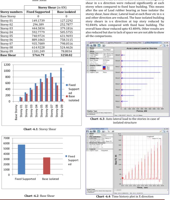
Table -6.1: Result value for the different storey shear and Base Shear
Storey Shear (in KN) Storey numbers Fixed Supported Base isolated
Base Storey 0 0
Storey 01 149.1739 127.2292
Storey 02 296.389 252.7877
Storey 03 444.5834 379.1816
Storey 04 592.7779 505.5755
Storey 05 740.9724 631.9693
Storey 06 889.1063 758.3115
Storey 07 935.7009 798.0516
Storey 08 614.9228 524.4626
Storey 09 1101.249 78.8034
Base Shear 5764.79 3258.02
0 200 400 600 800 1000 1200 Bas e St o re y Sto re y 01 Sto re y 02 Sto re y 03 Sto re y 04 Sto re y 05 Sto re y 06 Sto re y 07 Sto re y 08 Sto re y 09 Fixed Support ed Base isolated
Chart -6.1: Storey Shear
0 1000 2000 3000 4000 5000 6000 7000
Fixed Supported Base isolated
Fixed Support ed
Chart -6.2: Base Shear
Story shear is the shear generated at each storey during seismic action while the base shear is the required amount of reactive shear force to make the structure fully stable during seismic action. It can be seen in base isolated building story shear in x-x direction were reduced significantly at each storey when compared to fixed base building. This means after the use of Lead rubber bearing as base isolator the storey shear, base shear, Lateral load at each floor etc in x-x and other direction are reduced. The base isolated building story shears in x-x direction at top story reduced by 92.844% when compared with fixed base building. The overall base shear reduced upto 43.484%. Other results are also reduced but due to lack of space we are not able to show all the comparisons.
Chart -6.3: Auto lateral load to the stories in case of isolated structure
[image:10.595.35.578.137.776.2]© 2019, IRJET | Impact Factor value: 7.211 | ISO 9001:2008 Certified Journal | Page 3452
7.
FUTURE SCOPE OF BASE ISOLATION Seismic isolation is particularly useful for low-to me-dium rise buildings which happen to have their fundamental frequencies within the dangerous-for-resonance range of dominant earthquake frequencies.
Critical facilities, such as emergency response centre, hospitals, fire-stations, utilizes and communication centre, should remain operational of such essential, for the public interest, facilities may be prevented by using seismic isolation to enhance their earthquake capacity by reducing the seismic loads that they may experience during a powerful earthquake
It is very useful, and is probably the only currently available technology that can be used, to seismically upgrade historic structures or to protect very sensi-tive equipment and the valuable contents of a building.
8. LIMITATIONS OF BASE ISOLATION
A seismic isolation is generally suitable for low-
to medium-rise buildings which have their
fundamental frequency in the range of the
usual dominant frequencies of earthquakes
It is not suitable for structure resting on soft
soil and become less efficient for high rise
building
9. CONCLUSIONS
Fixed based and base isolated by providing lead rubber bearing were analyzed by Time History analysis from these building models following conclusions can be made.
Storey shear reduced for each storey after the lead rubber bearing (LRB) is provided as base isolation system which reduces the seismic effect on building Base shear is also reduced after providing LRB
which makes structure stable during earthquake Storey drift are also reduced for each storey
specially in higher stories which makes structure safe against earthquake
Point displacements are increased in every stories after providing LRB which is important to make a structure flexible during earthquake
Mode periods are increased which increases reaction time of a structure during earthquake Finally it is concluded that after LRB is provided as
base isolation system, it increases the structural stability against earthquake and also reduces reinforcement hence make structure economical. Base shear reduced up to 3258.02 KN in case of
base isolated structure as compared to that of the
5764.79 KN in case of fixed base supported structure.
ACKNOWLEDGEMENT
None of the paper is one person’s effort alone. For this one, too, we have many to thank. First of all we would like to thank our parents and family members for all the trust over us, we are really very lucky to have family like that who support us at every point of life. Then we would like to thank all the faculties and teachers and seniors for providing us knowledge and sharing their own knowledge and experience with us. We would also thank our friends and classmates for the support and also our critics too as their challenge always help us to be energetic and well focused towards our project work.
In time of Instagram, Facebook, Whatsapp and YouTube, you also deserve thanks for picking up this Journal and especially picking up this paper. At last but not least we are really very very thankful too those authors too who published their knowledge and expressed their knowledge through various mediums and also those who are creating awareness among engineers and others for any such techniques. We are also very thankful to this joural too for providing us such platform.
REFERENCES
[1] Swapnil Ambasta, Dushyat sahu & G.P. Khare, “Analysis
of base isolated building (Lead Plug Bearing) in ETABS”. 2018M. Young, The Technical Writer’s Handbook. Mill Valley, CA: University Science, 1989.
[2] Alpa Seth, Sudhir K. Jain,& Thiruppugazh V.
“Earthquake Capacity Build-ing and Risk reduction measures in Gujarat Post 2001 Earthquake.” 13th WCEE Aug., 2004 P. No. 2018.
[3] Miss. Sushma G. Sawadatkar & Mr. Madar M. Joshi, “A
review paper on base isolation technique”2017.
[4] Ajai kumar Rai “A critical review on base isolation’’2016.
[5] Vekatesh & Mr. Arun Kumar. “Dynamic Analysis of 11
Storey RC struc-ture by providing Lead Rubber Bearing (LRB) as Base Isolation Sys-tem”.2016.
[6] Rupam saikia M “soil liquefaction potential studies of
Guwahati city’’2014.
[7] Fabio Mazza “Base isolation techniques for seismic
protection”2008.
[8] Tian Xue min “Design of base isolated structure with
rubber bearing’’2008.
[9] Dinesh Dhanji Patel, Deviji Kuverji Patel, Khimji Lalji
Pindoria. “causes of damages that occurred in Bhuj earthquake, Gujrat, India, of 2001.
[10] Ramakrishnan.v. “Strengthening of RC Beams by using
BFRP”2003.
[11] IS 456:2000, Code of practice for plain and reinforced
concrete.
[12] IS 875, Code of practice for design loads (part 1 dead
© 2019, IRJET | Impact Factor value: 7.211 | ISO 9001:2008 Certified Journal | Page 3453
[13] IS 13920, 1993, Indian Standard Code of Practice for
Ductile Detailing of Reinforced Concrete Structures Subjected to Seismic Forces.
[14] IS 13935, 1993, Indian Standard Guidelines for Repair
and Seismic Strengthening of Buildings – Guidelines.
[15] IS 15988:2013 seismic evaluation ad strengthening of
existing reinforced concrete building- Guidelines.
[16] IS 13827, 1993, Indian Standard Guidelines for
Improving Earthquake Resistance of Earthen Buildings.
[17] IS 13828, 1993, Indian Standard Guidelines for
Improving Earthquake Resistance of Low Strength Masonry Buildings.
[18] IS 4326:2013, Indian Standard Code of Practice for
Earthquake Resistant Design and Construction of Buildings (3rd Revision).
[19] IS 1893 (Part I), 2016, Indian Standard Criteria for
Earthquake Resistant Design of Structures (6th Revision).
[20] UBC 97
[21] UBC 97 Isolated
BIOGRAPHIES
Anant Vats is currently pursuing Bachelors degree program in Civil engineering in Dev Bhoomi Institute of Technology, Dehradun affiliated under Uttarakhand Technical University, India, PH-9472578694 or 8709065096.
Ankit Kumar Singh is currently pursuing Bachelors degree program in Civil engineering in Dev Bhoomi Institute of Technology, Dehradun affiliated under Uttarakhand Technical University, India, PH-8084562885 or 8987045502.