© 2019, IRJET | Impact Factor value: 7.34 | ISO 9001:2008 Certified Journal
| Page 608
Design and Development of Arduino Based Radiation Survey Meter
with Two Scintillation Detectors
Ariful Alam
1, Dr. Md. Abdul Mannan Chowdhury
2, Fahmida Akter
31
Lecturer, Department of physics, Mawlana Bhashani Science and Technology University, Santosh, Tangail,
Bangladesh.
2
Professor, Department of Physics, Jahangirnagar University, Savar, Dhaka, Bangladesh.
3
Principal Engineer, Institute of Electronics, Atomic Energy Research Establishment, Savar, Dhaka, Bangladesh.
---***---
Abstract: An Arduino uno R3 (new generation high performance microcontroller) based radiation survey meter has been
designed and developed that has two scintillation detectors. A square wave pulse train of 16 KHz frequency was generated from the Arduino to produce high voltage (1200 volt). This regulated high voltage (1200 volt) power supply was used to activate the scintillation detectors. Two pre-amplifier circuits and two amplifier circuit were designed to amplify the small output signal of the detectors. It can be used for measuring radiation coming from a radiation source by using just one scintillation detector while another detector being in off mode. It also can be used for measuring radiation by surrounding a source by two scintillation detector which can be used for analyzing the absolute efficiency (the ratio of the number of counts recorded by the detector to the number of gamma rays emitted by the source in all directions) of radiation detector. For this purpose a summing circuit was used to add two individual amplified signals to provide total pulse. The Arduino microcontroller senses and processes the pulses and show the result through a liquid crystal display. The programming language C has been developed for pulse generation and to control the function of Arduino. The performance of the developed system was tested and compared with CANBERRA NIM counter. The performance of the designed system was quite satisfactory.
Keywords : Arduino uno R3, scintillation detector, amplifier circuit, liquid crystal display.
1. Introduction
Radiation means emission of energy in the form of waves or particles from a source. Radiation can transmit through a medium or space. There are two kinds of radiations, ionizing radiation and non-ionizing radiation. Ionizing radiation is the radiation that carries enough energy to ionize atoms or molecules. It has high energy, high frequency and short wavelength. The non-ionizing radiation has less energy and frequency. Gamma rays, X-rays, and the higher ultraviolet part of the electromagnetic spectrum are examples of ionizing radiations whereas sunshine is the familiar example of non-ionizing radiation. Ionizing radiations can be emitted from many kinds of natural materials, electronic devices such as x-ray machine, and also from the unstable atoms. The unstable atoms obtain stability by emitting energy or mass. This energy is emitted in the form of electromagnetic radiations and the mass is emitted as very small particles. This kind of emission is called nuclear radiations and these atoms are called radioactive atoms. Gamma radiations is example of electromagnetic radiation while alpha and beta radiations are example of particle radiation [1]. Ionizing radiation can be used for various beneficial purpose such as medicine, diagnostics, food processing, agriculture, industries and research laboratories. But the ionizing radiation can be harmful for human and environment. Exposure to ionizing radiation can cause burns, radiation sickness, cancer and genetic damage [2]. For the safety of public health and the environment the radiation must be measured and controlled during its applications. As human do not have any biological radiation sensor, so development of a high performance radiation survey meter has become very important for radiological safety.
This work is an attempt to design and development of Arduin based radiation survey meter using two scintillation detectors. A high performance Arduino Uno R3 microcontroller has been incorporated to control whole function of the developed system. Arduino is an open source prototyping platform which has ATmega328 chip, 32 KB flash memory, 2 KB SRAM, 1KB EEPROM and 16MHz clock Speed. It is easily connectable with other devices such as sensors, display circuits, computers and easily programmable [3].
© 2019, IRJET | Impact Factor value: 7.34 | ISO 9001:2008 Certified Journal
| Page 609
2. Design ConsiderationThe main part of the proposed system is Arduino UNO R3 microcontroller. Other parts of the developed system are: low voltage power supply circuit, high voltage power supply circuit, detector circuit, pre amplifier and amplifier circuit, summing circuit and display circuit.
2.1 Low Voltage Power Supply
A low voltage power supply of around 5 volt is required to power the Arduino or the microcontroller and other electronic components. Here a low voltage power supply circuit was developed to provide 5 volt regulated dc power supply. The main power was collected from 220 volt ac line. A step down transformer having primary winding 400 turn and secondary winding 40 turn was used in this design to convert 220 volt ac to 22 volt ac [4].
A bridge rectifier circuit was connected to rectify the 22 volt ac voltage to 22 dc voltage. This output voltage from the rectifier circuit may fluctuate, so a regulator should be used to regulate the output of the rectifier circuit. A L7805 IC was used to regulate the dc output and finally 5 volt regulated dc power supply was obtained from the circuit.
Fig.1: Circuit diagram of low voltage regulated power supply
2.2 High Voltage Power Supply
A regulated high voltage power supply of about 1200 volts is applied for the operation of the scintillation detector. For generating 1200 volts, a high voltage power supply circuit was developed. That circuit uses 5 volt as its input and generates 1200 volts at the output.
The high voltage power supply circuit consists of the following components [5]:
Pulse generation with a Arduino (microcontroller)
Step up transformer
Voltage quardrauple multiplier circuit
Sampling circuit
Voltage reference circuit
Error amplifier circuit
220V
1000
µ
F
L7805
5V dc Output
© 2019, IRJET | Impact Factor value: 7.34 | ISO 9001:2008 Certified Journal
| Page 610
Fig.2: High voltage power supply circuit2.3 Detector Circuit
There are two detector circuits in the developed system, individual or the sum of the output of these two circuit can be counted. Each detector circuit consists of a scintillation detector with resistor and capacitor [6]. The output of the detector circuit is feed to the pre-amplifier and then to the amplifier.
2.4 Pre-Amplifier and amplifier
When radiation strikes the scintillator it causes it to give off photons of visible light. These photons pass through the crystal and strike a thin metal foil called a photocathode then the light enters the second part of the detector, called a photo-multiplier tube. When the photon hits the photocathode it causes an electron to be ejected from the photocathode. At the last stage of PMT a large number of electrons are ejected [7]. But the output signal is still very small and need to be amplified. So A CA3140 IC is used with inverting configuration to design a pre-amplifier. The amplifier circuit consists of a IC CA3140 and resistors. It is a non-inverting amplifier circuit which amplifies five times in the same phase of the pre-amplifier output signal [8].
2.5 Summing Circuit
Summing circuit consist of 741 IC, 100 KΩ resistors and a 5 volt regulated power supply. This is an inverting summing amplifier because output is the sum of inputs with a sign change [9]. The output from the amplifier circuits of two scintillation detectors are combined together to obtain a single voltage or signal.
2.6 Microcontroller
A microcontroller is a compact integrated circuit designed to govern a specific operation in an embedded system. A typical microcontroller includes a processor, memory and input/output units on a single chip [10].
In our design Arduino uno R3 microcontroller has been used. The Arduino Uno R3 is a microcontroller board based on removable, dual inline package AT328 AVR microcontroller having flash memory 32 KB, SRAM 2 KB, EEPROM 1 KB, Clock Speed 16 MHz. It has 20 input/ output pins [11]. It is a high performance easily programmable microcontroller which receives data from the summing circuit, processes it and display the result through a liquid crystal display.
2.7 Display Circuit
For displaying pulses from the scintillation detector a liquid crystal display can be employed which can show the analog detector’s pulse in digital way [12]. The LCD is a electrically modulated optical device that uses the light modulating properties of liquid crystal. These kind of crystal does not emit light directly unless a reflector is used to produce image in monochome [13].
Ar
d
u
in
© 2019, IRJET | Impact Factor value: 7.34 | ISO 9001:2008 Certified Journal
| Page 611
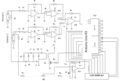
The LCD display is more convenient to connect and configure with Arduino. The LCD can display wide range of numerical value with associated data that’s why LCD become more popular in case of Arduino based project .Fig. 3: Block diagram of proposed system
Fig. 4: Circuit diagram of proposed system
Ar
d
u
in
o
Uno
[image:4.595.90.490.464.734.2]© 2019, IRJET | Impact Factor value: 7.34 | ISO 9001:2008 Certified Journal
| Page 612
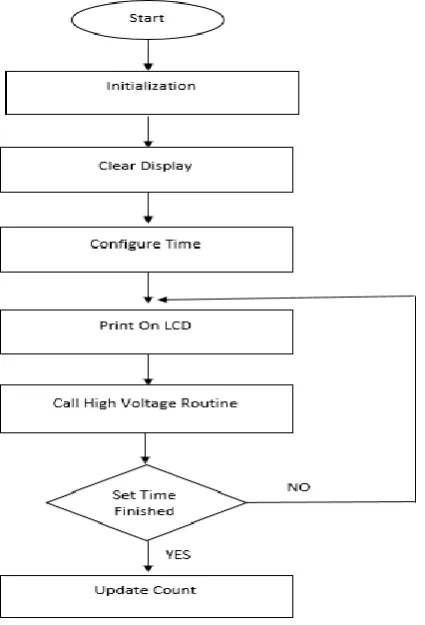
3. Programming [image:5.595.210.387.183.398.2]A single Arduino Uno R3 microcontroller has been used to perform all the functional operation of the developed system. Programming should be uploaded in to the microcontroller in order to perform the tasks such as high voltage signal generation, radiation signal count and for display the result. “C” programming language has been used to instruct the Arduino microcontroller [14]. The Arduino Genuino software is used to design the program and to upload the programming on to the microcontroller from a PC. Flowchart of the program are given below:
Fig. 5: Flow chart for high voltage pulse generation
[image:5.595.211.424.436.749.2]© 2019, IRJET | Impact Factor value: 7.34 | ISO 9001:2008 Certified Journal
| Page 613
4. ResultThe presented work has been planned and done in step-by-step process in a systematic way. At first the whole system including circuit connections and programming has been designed and tested in a computer simulation program named proteus 7 professional software [88]. After getting sufficient satisfaction from the computer simulation result, different parts of the circuit were developed practically and tested. Finally the whole system was developed and following test data were obtained:
The detector does not count any radiation below a certain applied voltage of about 650-670 volts. Above this voltage, the rate of count increases sharply . A steady state for counting the radiation appears for a wide range of applied voltage of about 850 volts to 1200 volts. So, the plateau region lies approximately in between 850 V to 1200 V range. In this developed system the scintillation detector has driven with approximately 1200 V power supply for better counting efficiency.
Chart-1: Plateau voltage region curve of scintillation detector
The system was calibrated using a radiation source from Cesium 137. The readings of the system were compared with the Canberra Nim Counter is shown in Figure below. From the graphs, it seems that the developed system is sound better.
Chart-2: Comparison graph between survey meter using one scintillation detector and CANBIRRA NIM
0 20 40 60 80 100 120 140 160 180
600 700 800 900 1000 1100 1200 1300 1400
Cou n ts p er se c Applied voltage
Voltage plateau region curve
0 50 100 150
900 930 970 1000 1030 1070 1100 1130 1170 1190
Cou n ts p er se c Applied Voltage
Comparison between developed system using one
detector and CANBERRA NIM
© 2019, IRJET | Impact Factor value: 7.34 | ISO 9001:2008 Certified Journal
| Page 614
We also measure the radiation count with two detectors by surrounding a Cesium 137 source from two direction to capture the total radiation emitted from the source which may help to analyze the absolute efficiency of the radiation detector [15]. [image:7.595.90.504.137.356.2]Chart-3: Radiation count using two detectors by surrounding a source
Table – 1: Specification of developed system
PARAMETER SPECIFICATION
Low voltage Power
supply 5 volt regulated dc power supply
Detector Two Scintillation detector PGS-3 of
Technical Associates, U.S.A
Crystal material NaI(TI)
Crystal diameter 1.00”
Crystal thickness 1.00”
High voltage 1200 volt
Amplifier circuit CA3140 IC for Pre-amplification
CA3140 IC for Amplification
Summing circuit LM741 IC for summing
Microcontroller Arduino Uno R3
( Atmega328 microcontroller)
Display Liquid crystal display (LCD)
5. Conclusion
The proposed system incorporates the uses of new generation high performance Arduino UNO R3 microcontroller and two scintillation detectors in developing a low-cost, high-accuracy radiation survey meter. It can be used to detect and measure the radiation from a source using only one detector or using the two detectors at a same time which may help for the further study of the absolute efficiency of the radiation detector. Again its costs approximately U$ 1000, whereas the price of the other ordinary radiation survey meter in the international market is not less than U$ 3000. The proposed system has been completed and tested through using both one detector separately or two detectors in combined and the results have proven the sound accuracy and reliability of the system. The features of our developed system has been compared with different types of radiation monitoring system and the result shows that the proposed system is of better choice due
145 150 155 160 165 170 175 180 185 190
900 930 970 1000 1030 1070 1100 1130 1170 1190
Cou n ts p er se c
Applied voltage in volts
Radiation count using two detectors
© 2019, IRJET | Impact Factor value: 7.34 | ISO 9001:2008 Certified Journal
| Page 615
to the low cost, high intrinsic efficiency and scope for laboratory analysis using two sensors for studying absolute efficiency of the radiation survey meter [15].6. References
[1] Harald A. Enge, “Introduction to NUCLEAR PHYSICS”, Third Edition, Addison-Wesley Publishing Company, P-191, 223, (1970)
[2] Herman Cember , Thomas E. Johnson, “Introduction To Health Physics” Fourth edition, McGraw-Hill Education (2008).
[3] “What is Arduino?” [Online]. Available: https://www.arduino.cc/en/guide/introduction. (Accessed: 15-Mar-2015).
[4] V.K. Mehta, “PRINCIPLES OF ELECTRONICS” Revised Edition, S. Chand & Company Ltd. (2003)
[5] Md. Abdullah-Al-Mashud, M.R.A. Bhuiyan and Md. Serajul Islam “Design and Development of A Microcontroller Based Regulated High Voltage Power Supply for GM Detectors“ ResearchGate, (November 2013).
[6] Leo, William R. “Techniques for Nuclear and Particle Physics Experiments”, Second Edition, Springer-Verlag Berlin Heidelberg, P-157-162, (1994).
[7] Paul Lecoq, Alexander Gektin, Milkhail Korzhik, “Particle Acceleration and Detection”, Second Edition, Geneva, Switzerland, (2006).
[8] Walt Jung, “Op Amp Applications Handbook”, Elsevier, P-123 , (2005).
[9] Donald P Leach, Albert Paul Malvino, Goutam Saha, “Digital Principles and applications” Seventh Edition, Tata McGraw Hill Education Private limited, (2011).
[10] Krishna Kant, “Microprocessors And Microcontrollers”, PHI learning Pvt. Ltd., New Dilhi, P-560- 569, (2007).
[11] Tianhong Pan, Yi Zhu, “Designing Embedded System with Arduino”, Springer, New York, P- 17, 45, (2017).
[12] Paul M. Embree and Bruce Kimble, “C Language Algorithms for Digital Signal Processing” Prentice Hall, Englewood Cliffs, New Jersey, (1991).
[13] Shozo Kokawa, Michiharu Nishihara, Yukikazu Sato “Liquid crystal display”, Publication number US5467208A, (1995).
[14] Brian Evans, “Beginning Arduino Programming” TIA & Apess, P-151, (2012).
[15] Akkurt, K. Gunoglu, and S. S. Arda, “Detection Efficiency of NaI(Tl) Detector in 511–1332 keV Energy Range”, Volume 2014, Article ID 186798, Science and Technology of Nuclear Installations, 2014.
Biographies