HARDWA E AND
SOF WA E
D VELOPMENTS FOR
APPLIED DIGITA
MAGE PROCESSING
A thesis presented for the degree of Doctor of Philosophy
in Electrical and Electronic Engineering in the University of Canterbury.
Christchurch, New Zealand.
D.G. BAILEY (E ons 1)
(i)
STRACT
This thesis discusses some of the problems and practices of applying digital image processing to scientific and industrial problems.
An interactive image processing system is described. This system has been found to be useful for the development of image processing
commands and algorithms to solve image processing problems. An image capture subsystem based around a 576 x 385 element frame transfer charge coupled device is described. This system has a variable integration time, giving it considerable flexibility over more conventional cameras.
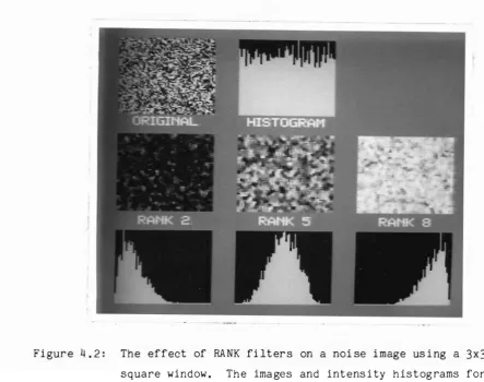
The properties of the RANK filter are described. The usefulness of this nonlinear filter is demonstrated by its performance on a number of common image processing tasks. The edge detection properties of RANGE filters, which are the difference between the outputs of two RANK filters, are discussed. This family of filters has considerable flexibility in the type of output response obtained, but was found to be slightly more
sensitive to noise than the commonly used SOBEL filter.
A new iterative solution to the Fourier phase retrieval problem is described, This solution is less efficient than current solutions, but does prove the optimality of an operation common to existing iterative methods of solution.
An approach to developing algorithms to solve image processing problems is described. The various commands that may be used at each stage are discussed. Although this approach does not say which command should be used when, it does provide a guide.
The algorithms developed for three applications are presented. These are: the calibration of a photoelastic material used in the
(Ul)
TABLE 0 CONTENT
ABSTRACT
TABLE OF CONTENTS
ACKNOWLEDGEMENTS
PREFACE
GLOSSARY
CHAPTER 1: INTRODUCTION. 1.1 BACKGROUND.
1.2 APPLICATIONS OF DIGITAL IMAGE PROCESSING. 1.2.1 Image coding
1.2.2 Computer assisted vision 1.2.3 Computerised vision 1.2.3.1 Inspection
1 .2~3.2 Manipulation. 1.3 DISCIPLINES INVOLVED 1.3.1 Object illumination
1.3.2 Image capture 1.3.3 Image processing 1.3.3.1
1.3.3.2 1.3.3.3 1.3.4
Algorithm development. Operator development
Algorithm implementation. Display
1.3.5 Control 1.4 SUMMARY.
CHAPTER 2: VAX IMAGE PROCESSING SYSTEM • 2.1 BACKGROUND.
2.2 SPECIFICATIONS AND CAPABILITIES
Page
1
• 111
xl
x11i
• xix
Purpose
Interact! ve • Command based VIPS programs
Ease of extension •
(iv) 2.2.1 2.2.2 2.2.3 2.2.11 2.2.5 2.2.6 2.2.7 2.2.8 2.3 2.3.1
Symbolic reference of all variables • Variable image size
2.3.2 2.3.3 2.11 2.4.1 2.4.2 2.4.3 2.5
Commands available
COMPARISON WITH OTHER SYSTEMS HIPS
UCIPS • VICAR system IMPLEMENT A T ION
Execution sequence VIPS as a procedure Error handling • SUMMARY •
CHAPTER
3:
HIPS CAMERA3.1 NEED FOR A LABORATORY CAMERA. 3.2 IMAGE CAPTURE SUBSYSTEM
3.2.1 3.2.1.1 3.2.1.2 3.2.1.3 3.2.1.11
The camera The sensor Clock drivers Video amplifier . Thermoelectric cooling 3.2.2 Waveform generator
3.2.3 Frame grabber
3.2.3.1 Analogue to digital conversion 3.2.3.2 Direct memory access
3.3
SOFTWARE INTERFACE 3.11 SPECIFICATIONS 3.5 SUMMARY.CHAPTER ll: RANK FILTERS • 4.1 INTRODUCTION
4.2 DEFINITION OF RANK FILTERS 1l.3 REVIEW OF PROPERTIES
4.3.1 4.3.2 4.3.3 4.3.4 4.3.5 4.3.6 4.3.7 4.3.8 4.3.9 4.3.10 4.4 4.5 4.6 4.6.1 4.6.2 4.6.3 4.6.4 4.6.5 4.6.6 4.7 (v)
Property 1: Noise smoothing Property 2: Intensity change. Property 3: Edge preservation Property 4: Edge shifting • Property 5: Invariant images. Property 6: MIN and MAX filters. Property 7: Local minima and maxima
Property 8: Commutation with monotonic functions Property 9: Complement property.
Property 10: No new intensity values FAST METHODS
HARDWARE SYSTEMS FOR MEDIAN / RANK FILTERING APPLICATIONS OF RANK FILTERS .
Application 1: Noise suppression
Application 2: Low pass, band pass and high pass filtering
Application 3: Shrinking and expanding, skeletising Application 4: Streak and spot / cluster detection Application 5: Edge detection.
Application 6: Edge enhancement SUMMARY AND CONCLUSIONS
CHAPTER 5: RANGE FILTERS 5.1 INTRODUCTION
5.2 BENCHMARK SELECTION
5.3 EFFECT OF RANGE FILTERS ON BINARY IMAGES . 5.3.1 5.3.2 5.3.3 5.3.4 5.3.5 5.3.6 5.3.7 5.3.8 5.4 5.5 5.6 5.7
Response to horizontal and vertical edges . Response to 45 degree diagonal edges
Detected edge width
Response to general diagonal edges Connect! v ity
Dependence on window shape and size • Comparison with SOBEL
Application - kiwifruit shape outline EFFECT ON A UNIFORM SLOPE .
EFFECT ON A NOISE IMAGE COMPARISON METHODS EDGE DETECTION IN NOISE
5.7.1 5.7.2 5.7.3 5.8 5.9 (vi)
Edge uncertainty measurements • Point noise •
Additi ve noise •
EFFECT OF WINDOW SHAPE AND SIZE • SUMMARY AND CONCLUSIONS
CHAPTER 6: THE FOURIER PHASE PROBLEM 6.1 INTRODUCTION
6.2 DEFINITIONS 6.2.1 6.2.2 6.2.3 6.2.4 6.3 6.3.1 6.3.2 6.4 6.4.1 6.4.2 6.5 6.6 6.6. 1 6.6.2 6.7
Image types • Fourier transforms Other operations Fourier phase problem CONDITIONS FOR UNIQUENESS •
One dimensional case • In higher dimensions . ITERATIVE SOLUTIONS •
Error reduction algorithm Input - output algorithm CRUDE PHASE ESTIMATION •
ATTEMPTED SOLUTIONS USING A SINGLE SPACE . Image space •
Fourier space CONCLUDING REMARKS
CHAPTER 7: ALGORITHM DEVELOPMENT 7.1 INTRODUCTION
7.2 OBTAIN REPRESENTATIVE IMAGE 7.3 PREPROCESSING.
7.3.1 7.3.2 7.3.3 7.3.4 7.3.5 7.4 7.4.1 7.4.2 7.4.3
Image capture compensation . Image normalisation
Filtering Thresholding Segmentation
INFORMATION EXTRACTION • Feature extraction Measurement •
Pattern identification / classification
95 97 98 • 103 • 103
• 105 · 105 • 106 • 106 • 106 · 107 • 108 • 108 110 • 111 • 112 • 112 • 113
• 1 15 • 117
• 119 • 1 21 · 124
· 127 · 127
• 129
• 129 • 130
(vii )
7.5 POSTPROCESSING
·
1387.6 ALGORITHM REFINEMENT • 139
7.7 DISCUSSION •
·
139CHAPTER 8: FOOTMGROUND PRESSURE DIS TR I BUTI ON MEASUREMENTS
·
1438.1 INTRODUCTION • 143
8.2 THE EQUIPMENT •
·
1438.3 THE IMAGE PROCESSING PROBLEM • • 147
8.4 DISCUSSION . • 150
8.5 CONCLUSIONS
·
153CHAPTER 9: TREE GROWTH RING MEASUREMENTS • 157
9.1 INTRODUCT ION
·
1579.2 APPROACH TAKEN
·
1589.3 THE TRACKING ALGORITHM •
·
1599.3.1 Basic algorithm
·
1639.3.2 Limiting the positions examined
·
1639.3.3 Search order methods •
·
1669.3.4 Using multiple pixels in the difference
·
1679.3.5 Pixel classification method
·
1679.3.6 Incorporating lookahead • · 168
9.3.7 Possible extensions • 168
9.4 AREA DETERMINATION
·
1699.5 THE FINAL ALGORITHM
·
1719.6, DISCUSSION / CONCLUSIONS
·
174CHAPTER 10: KIWIFRUIT SURFACE BLEMISH DETECTION • • 179
10. 1 INTRODUCTION •
·
17910.2 CLASSES OF DEFECTS •
·
18010.3 IMAGE PROCESSING APPROACH
·
18110.3.1 The VALLEY FILL algorithm.
·
18210.3.2 The CONVEX HULL algorithm •
·
18610.4 THE IMAGE PROCESSING ALGORITHM •
·
19110.4.1 The steps in the algorithm
·
19110.5 RESULTS
·
19510.5.1 Determination of threshold values
·
19510.5.2 Classification performance
·
198CHAPTER
(viii)
10.6 IMPLEMENTATION POSSIBILITIES 10.7 CONCLUSIONS
11 : SUMMARY AND CONCLUSIONS • 11. 1 OBJECT ILLUMINATION 11.2 IMAGE CAPTURE
11.3 IMAGE PROCESSING
11.3.1 Command development • 11.3.2 Algorithm development 11.4 DISPLAY OR CONTROL • 11.5 CONCLUSIONS
REFERENCES
APPENDICES
APPENDIX 1: FUNCTIONAL SUMMARY OF VIPS COMMANDS AND UTILITIES Al.1 COMMAND CATEGORIES.
Al.2 COMPLEX IMAGE MANIPULATION Al.3 DATA CONVERSION.
Al.4 DATA OUTPUT
Al.5 DATA EXTRACTION. Al.6 DISPLAY ROUTINES A 1 .7 FILTERS
Al.8 IMAGE MANIPULATION.
A1.9 IMAGE GENERATION AND RETRIEVAL. Al.l0 LINE DRAWING ROUTINES.
Al.11 POINT OPERATORS ON TWO IMAGES
Al.l2 POINT OPERATORS ON A SINGLE IMAGE. Al.13 VIPS CONTROL PROCEDURES
A1.14 VIPS PROGRAM COMMANDS. Al.15 MISC VIPS COMMANDS. Al.16 MISC UTILITIES
APPENDIX 2: CORRESPONDENCE WITH D.J. BURT ABOUT HIPS CAMERA
A2.1 MY LETTER • :.
A2.2 HIS REPLY.
• 201 • 205
• 209 • 209 • 210 • 210 • 211 • 211 • 212 • 212
• 215
• 239
· 241 • 241 • 242 • 242 · 242 • 242 · 243 • 243 • 243 · 244 • 244 • 244 • 244 • 245 • 245 • 245 • 246
APPENDIX 3: A3.1 A3.2 A3.3 A3. !j A3.5 A3.6
FILTER CHIP PROPOSAL • NEED FOR THE CHIP CHIP FUNCTIONS CHIP ARCHITECTURE
(ix)
IMAGE INTERFACE REQUIREMENTS ESTIMATED COST •
ESTIMATED SPEED •
APPENDIX !j: PROOF OF CONVERGENCE OF a + 0.5(1 + 1/a2 ) •
• 255 • 255 • 255 • 256 • 260 • 261 • 262
(xi)
ACKNOWLEDGEMENTS
I would like to express my sincere thanks to my supervisors Dr Bob Hodgson and Professor Richard Bates for their guidance and encouragement, and many helpful suggestions throughout the work described in this thesis.
I would also like to thank my colleagues of the biomedical and applied image processing groups for their support. In particular I would like to thank Richard Fright, Daniel Mnyama, Richard Lane, Alastair Sinton, and Stephen McNeill. I am also grateful to Jeremy Wilson and Matthew
Naylor for their suggestions and assistance in coding some of the VIPS commands, and to Roger Blick for his preliminary work on the kiwifruit grading problem.
The technical support of Mike Hostead in the design and construction of the HIPS Sensor circuit board and camera body is
appreciated. For construction and low level programming of the VIPS image display, I would like to thank Richard Cox and Andrew Earl.
During the courSe of this work, I was supported financially by a University Grants Committee postgraduate scholarship. The following
organisations provided research contract funds for the projects that I was involved with: The Forest Research Institute; New Zealand Kiwifruit
Authority; and the Bay of Plenty Fruitpackers Cooperative.
I would like to thank Lee Leonard for draughting the diagrams used in this thesis, and the personnel of the University photographic department for the printing of the photographs used in this thesis. I would also like to thank Laurie Hill for the preparation of photographs and slides for various presentations during the course of this thesis.
I would like to thank God for the many prayers he has answered, and the strength that he has provided throughout the projects I that worked on. Finally I would like to thank my parents for their encouragement and
(xiii)
PREFACE
When I first decided to come to University, I had difficulty deciding whether to do mathematics or computer science. In the end I decided to do electrical engineering since I was interested in electronics as a hobby. My interest in image processing was aroused at the end of my second professional year when I did my second period of practical work within the Electrical Engineering Department here at Canterbury. I was working in the image processing group for Dr Bob Hodgson and two of his ME students Jeff Atkinson and Duncan Hall. This work involved designing a video amplifier for the flying FADS system, and software development for a spectrograph readout system.
Towards the end of my BE, I decided that I would like to do
research, so I approached Dr Bob Hodgson about possible projects in image processing. At that meeting, we decided that it would be good for me to become familiar with, and understand, the field of applied image
processing. My provisional topic at that stage was 'Image Processing for Science and Industry'. Since Dr Hodgson was about to leave for nine months sabatical, I also approached Professor Richard Bates about doing some work with him.
Within the applied image processing group. a lot of the work tends to be project oriented. This is because a significant portion of the funding comes from industry or research institutes. In such situations, image processing problems often come with the funds. In a lot of these applications the work is done as a team, if not explicitly, then by
(xiv)
It was for the reasons mentioned above that I worked on many quite different projects, The approach taken was to work on two or three
applications and discover from a practical viewpoint what image processing involves. This was accompanied by a broad literature search into the
techniques that could be used at various places within the image processing algorithms.
Following is a brief chapter by chapter synopsis of this thesis. Each chapter contains a separate project and is relatively independent of other chapters. In the descriptions, I will point out the part of the work that is my own contribution.
The first chapter provides a general introduction to the field of image processing. Particular emphasis is placed on the industrial
application side of image processing - machine vision. The disciplines involved in applying machine vision to a particular problem are described briefly.
The remainder of the thesis comes under three main categories: systems, operators, and algorithm development.
Chapter 2 describes the VAX Image Processing System (VIPS) concentrating on some of its more novel features. It started as the limited subset of image processing commands that I needed to perform a large number of repetitive tests on RANGE filters. After an image display was added, the VIPS command language was developed and the number of image processing commands was increased to give what is now known as VIPS. Two technicians, Richard Cox and Andrew Earl, developed the display hardware and wrote the low level software required to drive the display. This provided an image display facility around which I built the image processing software. The development of VIPS has proved timely as is indicated by its popularity, from both within the department, and outside. The Wool research Organisation of New Zealand and Forest Research Institute are to acquire copies of the VIPS hardware and software for their own use.
The third chapter describes an image capture subsystem built for the High resolution Image Processing System (HIPS). Many people were involved
(xv)
effort was on the clock drivers, debugging and combining the other hardware to give a complete system. This chapter is included in the thesis as a matter of record.
The next three chapters examine the properties of some operators and techniques. Chapter
4
brings together the results of research on RANK filters. The relationship of RANK filters with other filters is briefly discussed. The main properties of RANK filters are listed and anexplanation is given for these properties. Several software and hardware implementations of the filter are described. Major applications to image processing are discussed, including noise smoothing, cluster detection, skeletisation, edge enhancement, and edge detection. The section on the use of RANK filters for edge enhancement is my major original contribution.
Chapter 5 examines the properties of the RANK based edge detection filter - the RANGE filter. The deterministic and noise properties of the RANGE filter are described and compared with the commonly used SOBEL filter. The work described in this chapter is original.
Professor Richard Bates suggested that I should look at the
possibility of solving the Fourier phase problem in a single space to avoid the need for repeated FFTs. Chapter 6 describes the current iterative solutions and examines the possibility of using a single space. No
convenient single space solution was found, but a proof of the optimality of one of the steps common to all of the iterative solutions was developed.
The next four chapters concentrate on algorithm development.
Chapter 7 outlines a "bottom up" approach to developing an algorithm. Some of the possible operators that may be applied at each stage are described briefly. The use of this approach is demonstrated on three applications in chapters 8 to 10.
Chapter 8 investigates the use of image processing techniques for measuring the foot ground pressure pattern of a standing person. I was approached by Wendy Johnston, then a student with the Mechanical
(xvi)
In chapter 9 the problem of measuring the area within tree growth rings is discussed. Of the possible image processing approaches to this problem, a method of tracking the growth ring boundaries was chosen. Several different tracking algorithms are presented, and their tracking performance compared on a test image. A method for calculating the area within the rings from the boundary is also described. Finally, the
resultant image processing algorithm is given, with preliminary results on actual tree cross sections.
The final application chapter, chapter 10, describes the
application of image processing techniques to detecting blemishes on the surface of kiwifruit. The approach adopted was to create a model of an
'ideal' fruit from the one being examined. The fruit is then compared with this model to locate the defects. The preliminary algorithm development work was carried out in conjunction with Roger Blick for his final year project. Later improvements in the modelling approach made the algorithm more robust. The current state of the algorithm is described with the results of using it to classify a sample of real fruit. Suggestions for further improvements are made, and some of the problems of practical implementation of the algorithm are addressed.
Chapter 11 presents a summary of the conclusions.
Following is a list of publications and presentations incurred during the course of this thesis.
Hodgson R.M" McNeill S.J., and Bailey D.G., 'Computers with "eyes" for inspection, measurement and automation', Institute of Measurement and Control Conference, Christchurch (May, 1983)
Hodgson R.M., Bailey D.G" and McNeill S.J., 'Computer vision for inspection, measurement, automation and robotics', National Electronics Conference, Auckland (August, 1983)
(xvii)
Bailey D.G., Hodgson R.M., and McNeill S.J., 'Local filters in digital image processing', National Electronics Conference, Christchurch (August, 198q)
Hodgson R.M., Bailey D.G., Naylor M.J., Ng A.L.M., and McNeill S.J., 'Properties, implementations and applications of rank filters', Image and Vision Computing, Vol 3, pp 1q (1985)
AID bit OOG byte CCD CID
CONVEX ~~
CPU DIP DMA DIA EPROM EVIL FET FFT FFT HIPS iRMX86 (xix)
LOSSARY
Analogue to Digital (usually refers to conversion) A single binary digit
A boundary tracking algorithm 8 bits
Charge Coupled Device (an image sensor) Charge Injection Device (an image sensor)
A modelling algorithm used in kiwifruit blemish detection Central Processing Unit
Dual In-line Package Direct Memory Access
Digital to Analogue (usually refers to conversion) Erasable Programmable Read Only Memory
Extensible Video Interactive Language Field Effect Transistor
Fast Frame Transfer (in a 'frame transfer' CCD sensor) Fast Fourier Transform
High resolution Image Processing System The operating system used by HIPS
kbyte 1024 bytes
MAX filter A special case of the RANK filter
Mbyte 1048576 bytes
MIN filter A special case of the RANK filter MEDIAN filter A special case of the RANK filter
MIP~512 A 512x512 capture and display board produced by Matrox MSBF Mean number of Steps Before Failure (of the BUG)
PED Peltier Effect Device (a thermoelectric cooling device) PIKKY The software image processing system run on UCIPS
pixel A picture element
P8600 The CCD sensor used in the HIPS camera RAM Random Access Memory
RANK filter A nonlinear filter
RANGE filter An edge detection filter derived from the RANK filter
SD Standard deviation
SNR TTL UCIPS
VALLEY FILL VAX 11/750 VAX/VMS VICAR VIPS VLSI VMOS 80186 8080 8086 8087
(xx)
Signal to Noise Ratio
Transistor Transistor Logic
University of Canterbury Image Processing System
A modelling algorithm used in kiwifruit blemish detection A 32 bit minicomputer produced by Digital Equipment Corp. The operating system commonly used by VAX computers
Video Image Communication and Retrieval VAX Image Processing System
Very Large Scale Integration
V-channel Metal Oxide Semiconductor (a type of FET) An enhanced 16 bit microprocessor produced by Intel An 8 bit microprocessor produced by Intel
,.. 1
-Chapter 1
INTRODUCTION
BACKGROUND
From time immemorial, man has been fascinated by his environment, Sight is one of the most important senses used by man as he has sought to manipulate the things around him, and understand the laws governing their behaviour. As man developed implements and machines to make it easier to manipulate his environment, he also developed machines and methods to assist and improve his vision. More recently, man has been adding vision to his machines to increase their power and flexibility.
2
-1.2 APPLICATIONS OF DIGITAL IMAGE PROCESSING
Image processing is best defined by the types of applications that it is used for. In a following section, the disciplines involved in the design and use of a digital image processing system are described.
There are three main application areas of digital image processing. The first is image coding, where the volume of data contained in an image is reduced for storage or transmission. Another area is the improvement of pictorial information for human interpretation. This is also called
computer assisted vision. The final application area is computerised vision where an image processing system is used to automatically extract information from, or analyse scenes or other images (Gonzalez and Wintz, 1977),
1.2.1 IMAGE CODING
Images contain large amounts of data, much of which is redundant. For example an image containing a single intensity is completely specified by the image size and the intensity. Useful images contain more
information than this, but often contain significant redundancy. When these images are stored, or transmitted from one place to another it is often desirable to compress the image so that it occupies less storage space, or takes less time to transmit. The processes of compressing the image, and recovering the original image from the compressed version are known as image encoding and decoding respectively. An excellent review paper on the techniques which can be used for image coding is Jain (1981).
1.2.2 COMPUTER ASSISTED VISION
Image processing is used in computer assisted vision primarily to augment human vision. However, similar techniques are also commonly used in the preprocessing stages of algorithms for information extraction and scene analysis applications ('7.3). The types of processes involved in computer assisted vision are image rectification, enhancement, restoration, and reconstruction (Bates and McDonnell, 1986).
~ 3
-by the imaging equipment (for example barrel or pincushion distortion from the lens), the viewpoint used (for example perspective distortion), or the nature of the object being imaged (for example rectifying satellite images to a particular map projection (O'Handley and Green, 1972».
Image enhancement is the term given to processes which improve the subjective quality of an image, or make it more suitable for subsequent processing (Pratt, 1978). The information that is enhanced is apparent in the or inal image, but is often unclear or clouded (Bates and McDonnell, 1986). Some of the processes involved in image enhancement are (Pratt, 1978) noise reduction, nonlinearity compensation, contrast adjustment, and edge sharpening. Two applications are the enhancement of Xray images (Gonzalez and Wintz, 1977) and the removal of fixed pattern transmission interference (Peli and Verly, 1983).
When the image has been degraded to the extent that the information in the image is unrecognisable, the process which recovers the information is known as image restoration (Bates and McDonnell, 1986). A priori
knowledge of the cause of the degradation process is used to develop an inverse process (Pratt, 1978). This inverse process is then applied to the degraded image to recover the original. An example of image restoration is the deblurring of severely blurred photographs (McDonnell and Bates, 1975).
Sometimes it is not possible to obtain an image in a convenient form for display, or other processing. Image reconstruction may be used to restructure the information in a more useful form. Examples of image
reconstruction are computer assisted tomography (Garden, 198~) and Fourier phase recovery (Bates, 198~; Bates and Fright, 1983).
1.2.3 COMPUTERISED VISION
When digital image processing is used to extract information from, or interpret scenes or other images, it is known as computerised vision, or machine vision. Machine Vision has been defined as "the automatic
, 4
-The concepts and processes described und~r computer assisted vision are often used in the preprocessing stages of such applications. This is discussed more fully in 117. The two main application areas of machine vision (Rosen, 1979) are inspection (figure 1.1) and manipulation (figure
1 .2) •
1.2.3.1 INSPECTION
Of the two types of application of machine vision, inspection is by far the larger. A survey in USA shows that 90% of the machine vision
market is in inspection and quality control (Schaffer, 1984). The United States Bureau of Census states that about one in every three assembly workers is an inspector (Hodgson et al., 1983). These are all potential
applications of automated inspection.
Figure 1.1 (from Rosen, 1979) gives a breakdown of the machine vision inspection applications. Inspection tasks may be split into two broad categories: those in which decisions are based on highly quantitative measurements, and those in which the measurements made are of a more
qualitative nature.
In quantitative, or measurement tasks, machine vision provides a powerful general purpose tool (Rosen, 1979). The use of solid state sensors enables accurate noncontact measurements to be made rapidly at potentially low cost. The type of information that may be of interest to in a measurement task is the length, area, or position of an object. Examples of object measurement are given in ~8 and 19.
HIGHLY QUANTITATIVE MENSURAT ION
CRITICAL DIMENSIONS
CRITICAL INTERIOR AND EXTERIOR DIMENSIONS OF KEY FEATURES OF WORKPIECES
TOOL WEAR
I
LABEL READING AND REGISTRATION
MACHINE VISION APPLICATIONS - INSPECTION
I
T
INTEGRITY ANDT
ALL PARTS AND FEATURES PRESENT, RIGHT PARTS, HANDEDNESS
I
BURRS CRACKS WARPING DEFECTSAPPROXIMATE SIZE AND LOCATION OF KEY FEATURES
QUALITATIVE AND SEMI QUANTITATIVE
MENSURATION
SORTING
I
COSMETIC AND SURFACE FINISH
PROPERTIES
I
STAINS, SMEARS COLOURS,
BLEMISHES, SURFACE
DISCONTINUITIES
Figure 1.1: Inspection applications of machine vision.
I
SAFETY AND
[image:28.841.82.767.72.492.2]malfunction, or improper operation if the component is used. Cosmetic defects reduce the subjective quality, without impairing performance.
The majority of inspection tasks are menial and have a high boredom factor. In fact the very nature of the problem that causes boredom is one of the prerequisites for the successful application of image processing techniques (Hodgson et al., 1983) since such tasks tend to be well defined and relatively simple. Machine vision is able to perform these tasks consistently and reliably allowing 100% inspection of all components produced (Kruger and Thompson, 1981). In fact some companies which subcontract a lot of their work (British Leyland for example) are also working towards 100% inspection on all incoming components. This minimises waste and increases production by ensuring that the final product does not incorporate any faulty components.
Although there is a wide variety of techniques are used among the different inspection systems that have been applied commercially, they all use a priori knowledge of the specific problem (Kruger and Thompson, 1981). In industrial situations, where the inspected components are usually man made, the regular geometry, such as straight lines and right angles, greatly simplifies the inspection task (Kruger and Thompson, 1981).
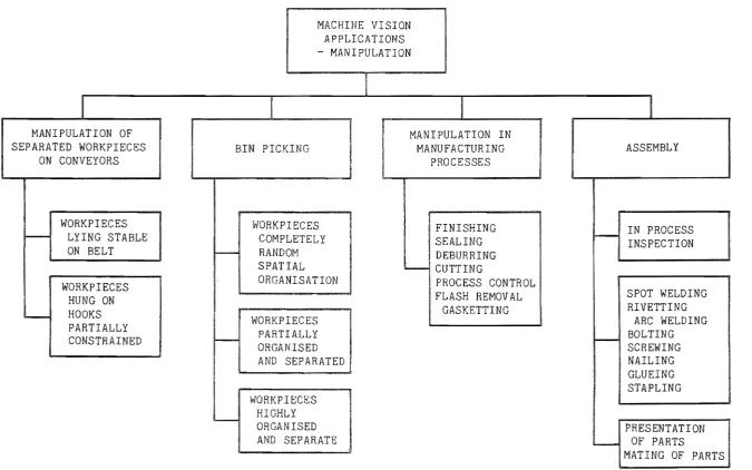
1.2.3.2 MANIPULATION
Machine vision is also playing an increasing role in manufacturing or assembly environments (Schaffer, 1984). A breakdown of machine vision manipulation tasks is given in figure 1.2. The main areas of application are in component acquisition, fabrication, and assembly (Rosen, 1979).
In the area of component acquisition, machine vision gives
increased flexibility (Gevarter, 1982b). The first generation of automatic machines required a very ordered environment. That is, the objects that were being manipulated had to be at the right place, in the right
orientation at the right time. With vision, this requirement can be
MACHINE VISION APPLICATIONS - MANIPULATION
I
I
I
I
I
MANIPULATION OF MANIPULATION IN
SEPARATED WORKPIECES BIN PICKING MANUFACTURING ASSEMBLY
ON CONVEYORS PROCESSES
WORKPIECES WORKPIECES FINISHING
I - - IN PROCESS
I - - LYING STABLE COMPLETELY SEALING
INSPECTION
ON BELT r-- RANDOM DEBURRING
....
SPATIAL I...-... CUTTING
ORGANISATION PROCESS CONTROL
WORKPIECES
FLASH REMOVAL SPOT WELDING
HUNG ON
GASKETTING RIVETTING
i . - HOOKS
WORKPIECES ARC WELDING
PARTIALLY
PARTIALLY I - - BOLTING
CONSTRAINED
r--ORGANISED SCREWING
AND SEPARATED NAILING
GLUEING STAPLING WORKPIECES
HIGHLY
'
-ORGANISED PRESENTATION
AND SEPARATE !....-- OF PARTS
MATING OF PARTS
[image:30.841.75.751.72.494.2],... 8
r-A large number of important process were unable to be automated in the past because of the small number of components manufactured in each batch. The small batch size meant that the cost of specialised jigs or dedicated production machinery is out of proportion to the returns obtained (Rosen, 1979). The use of vision overcomes this restriction by giving added flexibility in component and tool manipulation (Kruger and Thompson, 1981).
Visual feedback is useful in assembly tasks for alignment or mating of components, since it can be used to compensate for a buildup of
positional error in the components being manipulated (Rosen, 1979). When an assembly task is performed by humans, there is an implicit inspection of the components (Rosen, 1979). If a component which has an obvious defect is encountered, it is usually placed to the side and not incorporated into the final product. Inspection is being incorporated into the manufacturing and assembly stages of processes which are being automated in order to
maintain, and improve the overall quality of the end product (Rosen, 1979).
1.3 DISCIPLINES INVOLVED
My aim at the start of this research was to become familiar with, and to understand the field of machine vision. The different disciplines
involved in machine vision are introduced in this section, and the ones which were investigated in detail are discussed more fully in the rest of this thesis. Figure 1.3 identifies the disciplines .involved in machine vision.
1.3.1 OBJECT ILLUMINATION
Correct lighting is essential to simplify the processing of the captured image (Hodgson et al., 198~). It is difficult and often
impossible to compensate for poor image quality caused by unsuitable object illumination. Some of the problems that may be encountered are: a
non-uniformity of the illumination across the image; shadows or glints; and sometimes poor contrast. All of these problems can introduce false
,.. 9
-MACHINE
VISION
I
I
I
OBJECT
IMAGE
IMAGE
DISPLAY
ILLUMINATION
CAPTURE
PROCESSING
CONTROL
I
I
SENSORSI
DIGITISATION
ALGORITHM
IMPLEMENTATION
CAMERAS
AND DMA
DEVELOPMENT
Figure 1.3: Disciplines involved in machine vision.
techniques may be used to simplify the algorithm even further (Gevarter, 1982a). Some of these are discussed more fully in 17.2.
1.3.2 IMAGE CAPTURE
The process of obtaining a computer representation of the scene is known an image capture. There are two stages involved in image capture.
Object Lens
- 10 ,...
CONTROL CIRCUITS
Sensor
AID
Conversi
Figure 1.4: An image capture subsystem
DMA Memory
accumulated on the sensor, the two dimensional charge pattern is read out. This involves converting the charge associated with each picture element, or pixel, into a voltage. Since with most devices it is not possible to read out individual pixels at random, the device generates a serial train of discrete voltage pulses.
There is a wide range of sensors, both one and two dimensional, that may be used for image processing (Nagy, 1983). The dominant solid state sensor is the charge coupled device (CCO), although photodiode arrays and charge injection devices (CIO) are available (Hodgson et al., 1983). With CCO technology. it is possible to produce devices which are capable of performing some of the preprocessing operations on the chip (Barbe et al., 1980; Chamberlain, 1980). In applications where only a binary, or two level, image needs to be captured, an inexpensive camera based on a dynamic RAM chip can be constructed (Brook, 1983; Ciarcia, 1983; Grigor, 1983; Russell, 1983). An image capture subsystem based around a CCO sensor is described in
n.
In the second stage the electrical signal from the sensor is
11
-suitable for mensuration tasks. The resultant array of numbers
representing the object or scene is known as a digital image (Haralick, 1973) .
1.3.3 IMAGE PROCESSING
Once an image has been loaded into the computer, it may then be processed. This the application of a series of actions or operations to an
image which leads to a desired result (Castleman, 1979). This result may be the measurement of a critical dimension; a description of the object; or the classification of the object into one of several categories (for
example grading).
Most people take vision for granted. When they look at an object they can instantly recognise what it is, With machine vision, things are not quite so simple. The two main difficulties are developing the image processing algorithm from the specification of the problem, and
implementing the algorithm after it has been developed.
1.3.3.1 ALGORITHM DEVELOPMENT
There are three major problems in developing the image processing algorithm. The first of these is the problem of data reduction (Gevarter, 1982a). An image contains a large amount of information, a lot of which is
irrelevant to the problem being investigated. Consider for example the problem of grading kiwifruit (see '10). The input image contains 100 x 100 pixels, of 8 bits each, a total of 10kbytes. From this data it needs to be determined whether the kiwifruit being imaged is of export grade or not. That is the result is a single bit, corresponding to a data reduction factor of 80 000. In other applications, the input images may need to be 512 x 512 x 8 bits, or even larger.
- 12
-phase of solving a machine vision problem. A useful guide for interactive systems is that each operation should take less than 15 seconds (Cady et al., 1981). If the operations regularly take longer than this, the time delay becomes uncomfortable for the user. An interactive system must allow the operator to try a particular operation and examine the effect that it had on the image. If the result is unsatisfactory. another operation is tried in its place. Thus algorithm development requires much backtracking, and much interaction in order to determine the solution to the problem being examined. The VAX Image Processing System (VIPS) described in 2 was designed for interactive algorithm development.
~
Another problem encountered when developing algorithms is that images are only two dimensional representations of three dimensional objeots (Gevarter, 1982a). Information about the third dimension is important in traoking moving objeots, or picking up an object from an arbitrary position and orientation (for example from a bin). This information may be obtained through triangulation, the use of special lighting teohniques, or some other range finding techniques (for example sonar) (Jarvis, 1983).
1.3.3.2 OPERATOR DEVELOPMENT
It often transpires that an image processing operator not supplied with a development system is required in a particular application. In this instanoe, or when new techniques are being investigated, new operators must be developed. Any system used to develop algorithms to solve image
processing problems must have the ability to add new commands quiokly and easily (Brumfitt, 1984). Examples of the commands that were investigated
in the course of this work are the RANK (4) and RANGE filters (5).
1.3.3.3 ALGORITHM IMPLEMENTATION
One of the problems in implementing the algorithm, partioularly in an industrial environment, is the limited time available to perform the task (Gevarter. 1982a). A typical time requirement for an industrial
13
-example Young and Liu , 1981). or multiple computers (for -example Agrawal and Jain, 1981), although usually at considerable expense.
Another problem encountered in designing a machine vision system for a specific task is determining the optimum hardware and software combination required by the problem. One of the best approaches to this problem is to use an interactive prototyping system (Batchelor, 1979a; Hodgson et al., 198~).
1.3.~ DISPLAY
The interactive nature of the algorithm development stage requires some means of examining the image after an operator is applied. A video display is well suited for this purpose because of the speed with which it may be updated. The components of a typical display subsystem are a frame store, a DMA device, a digital to analogue convertor, and a video monitor. The frame store is a region of memory containing the image that may be accessed at video rates (100 ns per pixel in a 512 x 512 system). The image is read serially by the DMA and converted to an analogue voltage suitable for the monitor. The image capture and display sUbsystems are often combined together as a single hardware unit (for example the MI 12 video board (Matrox, 1984». This significantly reduces the memory
required, and makes image capture more convenient.
In computer assisted vision applications, where image processing is used to enhance images for human interpretation, a video display is the usual output device.
1.3.5 CONTROL
The output from a computerised vision system, however, is seldom an image display. The actual form of control hardware depends considerably on the application. In a sorting or inspection environment, the control may be a simple manipulator. If an inventory control system is incorporated, the data extracted from each image may be sent to another computer. When the machine vision system is used for a manufacturing or assembly task, the control hardware may be a robot arm or other manipulator. The common
1.4 SUMMARY
The range of applications of image processing has been developing rapidly as advances in both hardware and software have been made. Problems which were impractical in the past because of time constraints are now becoming practical. These advances will continue to be made as faster and cheaper computing becomes available. The advent of VLSI in recent years is providing a significant boost to image processing as it is enabling fast hardware to be constructed.
Until now, the development of algorithms for machine vision has been as much of an art as a science. This state of affairs is likely to continue for some time yet, although may change as a result of continuing research into human vision. Because of the general purpose nature of vision, image processing has been applied to diverse applications covering the complete spectrum of science.
,.. 17
-Chapter 2
VAX IMAGE PROCESSING SYSTEM
This chapter describes aspects of an image processing system that uses a VAX 11/750 as the host processor, and compares this system with others developed in the Electrical and Electronic Engineering Department at
the University of Canterbury.
BACKGROUND
The VAX Image Processing System (VIPS) evolved from the PIKKY operating system developed by Cady et ala (1980, 1981) for the Intel 8080 based University of Canterbury Image Processing System (UCIPS). VIPS is implemented in VAX PASCAL and is designed to run on Digital Equipment Corporation's VAX series of minicomputers. VIPS, or really a VAX based PIKKY system, started as a limited subset of the PIKKY commands needed to perform a large number of repetitive tests on the RANGE filters (15). This w~s necessary since PIKKY had very limited batch processing
facilities, and lacked a suitable output for the results of the tests. An image display was added, and for the initially limited set of image
18
-DISK
I
Display
r::::
:>
D
Frome
VAX
'" ...
..
~
.>
M
<
;;
Video
signal
r--...
",.,..".11/750
Store
lr---VIPS
A
I I~ftwar2.
!lIE I , L ____Camera
I II ,
...
Terminal
.,
Figure 2.1: Schematic diagram of the VIPS hardware.
2.2 SPECIFICATIONS AND CAPABILITIES 2.2.1 PURPOSE
The initial, limited purpose of VIPS was to investigate the
properties of RANGE filters, but it soon became evident that it was capable of much more. As the system grew, its usefulness and scope also increased. VIPS is now used as: a tool for use in developing algorithms to solve image processing problems; a self contained laboratory image processing system enabling routine tasks to be performed; and a research tool for use in developing new commands and techniques.
2.2.2 INTERACTIVE
As discussed in fi1, an image processing system needs to be
[image:41.595.73.530.81.289.2]~ 19
-filtering and Fourier transformation outside the 15 second guideline. The time taken for each command also increases as the host computer becomes more heavily used, but remains within the 15 second guideline for most commands operating on images with a resolution of 128 x 128 pixels or less.
2.2.3 COMMAND BASED
VIPS is a command based (Brumfitt, 1984) interactive image
processing system implemented in VAX PASCAL. This means that the commands run under a parent program, rather than directly under the VAX operating system. This is necessary to minimise the difficulty in maintaining a large data structure from one command to the next. The advantage of this scheme is that it provides a large library of image processing subroutines that may be called from other programs independent of the VIPS command language. The disadvantages of executing the commands under a parent program are that the program is much larger, leaving less memory space for images and other data, and that the host system commands are difficult to access. The first disadvantage is only significant when high resolution images are being processed (greater than 512 x 512 pixels). VIPS overcomes the second problem by creating an subprocess that enables the user to
operate at the host command language level. When the subprocess terminates, the user is returned to VIPS.
2.2.4 VIPS PROGRAMS
Often a sequence of commands requires repeated execution. VIPS allows users to enter a sequence of commands as a VIPS program. Features such as looping and branching are provided to allow flexibility in the command sequence that previously required user evaluation. Loop structures provide the means for repetitive testing of new commands and techniques. All of the looping and branching constructs necessary for a language
(Wirth, 1974) are available for use from within VIPS programs.
Although no effort is made to provide in VIPS a system for
20
-implementation of the algorithms developed in mind. HIPS will use much of the VIPS command software, minimising the translation problems from one system to the other.
2.2.5 EASE OF EXTENSION
When developing algorithms to solve particular image processing problems, it is often necessary to develop special purpose commands. VIPS is designed to allow new commands to be added easily, and be used as though they are part of VIPS. The data structures and methods that enable this to be done are detailed in a later section. Users are able to add their own private commands, which remain separated from other users' private
commands. The addition of user commands does not require relinking of the VIPS program. This independence of user commands from the VIPS core
commands speeds command development, especially when several users are working on different applications. The mechanism for this is described in
'2.4.2. However, when new commands are made available to other users as part of VIPS, the VIPS program does require relinking.
2.2.6 SYMBOLIC REFERENCE OF ALL VARIABLES
One of the features of VIPS is that all user variables are accessed symbolically, rather than by location, allowing the user to concentrate on the image processing problem. In practise this means that images and other variables may be given meaningful names, making algorithms easier to
develop and simplifying algorithm modification at a later date. A variety of predefined variable structures are provided, from general purpose
variables such as integers and real numbers, to structures used more specifically for image processing such as vectors and histograms. This large variety expands the capabilities of VIPS programs by enabling interaction between commands of more than just images.
2.2.7 VARIABLE IMAGE SIZE
VIPS is not limited to a single size of image. The image resolution can be adjusted to suit the requirements of the particular problem. This enables multiple resolution techniques (for example
21
-be used to speed processing where necessary. Two 2 dimensional image types are provided: integer images with 8 bits resolution per pixel, and complex
images with 6~ bits per pixel. A third type is provided for chain coded images consisting of a doubly linked list, with 32 bit integers provided for both the direction and value fields. Although in principle the image size can be unlimited, the processing speed and display size of 256 x 256 provide constraints. The storage space available for each image has been arbitrarily limited to 1 Mbyte. At present, since there is no image capture facility on VIPS, images are computer generated, or transferred from another system. The next logical extension to the VIPS hardware would be the addition of an image capture subsystem.
2.2.8 COMMANDS AVAILABLE
There are currently over 100 commands available to VIPS users, 70 of which are image processing commands. These include a comprehensive range of general purpose image processing operators and graphics routines. Online documentation provides all of the information required to use each command. Appendix 1 contains a summary of all of the VIPS commands.
2 COMPARISON WITH OTHER SYSTEMS
Two other image processing systems developed at the Department of Electrical and Electronic Engineering, University of Canterbury are UCIPS and HIPS. Comparison is also made with the VICAR (Video Image
Communication and Retrieval) system, described by Castleman (1979).
2.3.1 HIPS
HIPS is implemented on an 8086/8087 based microprocessor.
Application software is written in PASCAL, while the low level system
software is written in PLM/86. Like VIPS, HIPS is a command driven system, but unlike VIPS, the commands are called or executed from the operating system level. The operating system is Intel iRMX86 Which has been augmented to enable commands to access the image capture and display
22
-HIPS has been designed with prototyping in mind (Hodgson et al., 1984), This means that after the software has been developed to solve an image processing problem, the question of how it is to be implemented in practise in an industrial or other such setting can be addressed. If practical, a dedicated system can be designed from HIPS, containing the software and hardware required by the application. If this is not practical, valuable information can be obtained as to what is actually
~
required, and whether or not it is practical within the current limits of technology. VIPS can only provide a very limited insight about the final form of the application system since it is implemented on a relatively expensive, general purpose computer system.
2.3.2 UCIPS
The UCIPS system which first became operational in about 1978, although still of comparable functional power with currently available commercial systems, lacks the flexibility of its successors. The heart of the system is an 8080 CPU. Being very hardware specific, the system and its software lack portability. Like HIPS, UCIPS is command driven, using a special purpose PIKKY operating system. Commands are written in assembly language or PLM, making it difficult to develop complicated commands. Command development is complicated further by the very limited runtime support provided. This support must be developed as part of the command in most applications. In contrast to this, both HIPS and VIPS commands are able to make extensive use of system services.
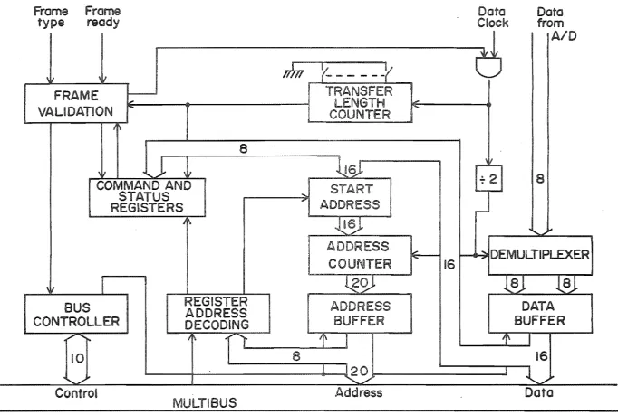
Limited command sequence processing is provided by the PIKKY
system, although it is restricted to only a few commands (100 characters in the buffer), and no looping or branching is provided. The only 'variables' allowed are images, and these are of fixed resolution (100xl00). There are
23
-DMA, a complete 256 x 256 transfer taking about 6 seconds. For this reason, a display command is used to update the VIPS display.
2.3.3 VICAR SYSTEM
The VICAR system consists of a library of image processing programs which are executed as tasks under a system supervisor.
view, it resembles HIPS more closely than it does VIPS.
From this point of All of the VICAR application commands are written in FORTRAN or assembly language. The use of FORTRAN precludes the use of dynamic variables which may be used
extensively in image processing in the form of linear lists (for example chain codes) or trees (as used by Handley (1985) for convex hull
extraction). Dynamic variables may be improvised in assembly language, but it was found from developing complicated commands for the UCIPS system ('2.3.2) that assembly language programming is time consuming when
compared with programming in a high level language. When new commands are developed for the VICAR system, they must be completely developed and
debugged independently before insertion into the system. VIPS allows users to freely develop and use new commands before adding them to the command library. This enables interaction with other commands to be examined and modified before insertion into the system. One of the advantages of the VICAR system over VIPS is the use of keywords to specify parameter values. This enables an unlimited number of parameters, with only those not being defaulted needing to be specified. With this method, the need to specify the keyword as well as the value when overriding the default is a
disadvantage if a large number of defaults are regularly overridden.
In the VICAR system commands are loaded through a card reader, and are translated into a job command language command stream. Commands may also be entered interactively through a keyboard, with processed images being displayed at the terminal. A limited looping structure is provided, consisting of executing a sequence of commands a fixed number of times on one or more images. VIPS provides more flexibility by allowing loops and branches to be dependent on data extracted from the images being processed. An extension to the VICAR system, EVIL (Extensible Video Interactive
211
-Images are processed on VICAR from tape input to tape output, with temporary images (from between commands) being stored on disk. This is one of the methods of overcoming the problem of maintaining image data from one command to the next when separate programs are used for each command. This method must be used within VICAR since very large images are regularly to processsed. A minor disadvantage of this method is the expense of the additional time required to access the image data, especially when random accessing of pixels is required (for example in region growing (Castleman,
1979) or boundary tracking ('9.3». No other variable types are provided by VICAR, making VIPS more flexible by comparison.
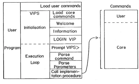
2 IMPLEMENTATION
This section describes briefly how the VIPS software is implemented. A schematic of this software is given in figure 2.2.
Program
Load
VI
Initialisation
commands
Load core
commands
leoma
Information
LOGIN VI
- - - / - - - 1
Execution
Loop
Prompt VIPS>
Parse
command
Parse
Parameters
Call
implemen-tation procedure
Figure 2.2: Schematic diagram of the VIPS software.
Commands
User
-
[image:47.595.60.534.381.667.2]25
-2.4.1 EXECUTION SEQUENCE
When VIPS is executed, there are two main phases of operation: system initialisation, and command execution. During the initialisation phase, the VIPS commands are loaded into the command table. The commands currently available are listed in Appendix 1. A welcome message is
displayed, indicating the current version of the software, followed by any information about new commands, or recent modifications to VIPS. The current directory is searched for the file LOGIN.VIP. This file, if present, is assumed to contain a VIPS program to perform any variable initialisations before the interactive prompt appears. The program contained in this file is loaded and executed.
The next phase of operation is to interactively execute VIPS
commands. A prompt is provided, and the user enters the command required. The command is parsed by searching in the command table for a match with
the command provided. A linked list is used for the command table since this allows any number of users' private commands to be added, Each link represents one of the available commands as shown in figure 2.3. The name field contains the full name of the command as used by VIPS, When a match is found between the command provided and the contents of the name field, the rest of the information about the command is extracted from the table. This consists of the address field which provides the location of the procedure that implements the command, and the parameter field which lists the type of each of the parameters required by the implementation
HAM
ADDRESS
NAME ADORESS
NAME ADDRESS
26
-procedure. Each procedure may have up to eight parameters. This limit is arbitrary. but necessary since the procedure call to load the command table must have a fixed number of parameters.
After parsing the command, the parameters are parsed according to the types provided by the command table. Variables are found by searching the variable table. a doubly linked list, the form of which is shown in figure 2.4. The name field contains the symbolic name used to access the variable. The value field contains the value of the variable where this fits into 32 bits. or a pointer to the variable if more space is required, as in the case of images. The type field notes the variable's type and is used for checking that the right type of parameters are passed to commands, and for determining how the value field is to be interpreted. If all the variables and other parameters are of the correct type, the procedure that implements the command is called. This process is repeated for each
command.
Variable
----~Table
NAME VALUE
NAME VALUE TYPE
NAME VALUE TYPE
Figure 2.4: Variable table linked list.
2.4.2 VIPS AS A PROCEDURE
27
-process of recompiling and relinking each time the command is modified. In the VIPS system this problem is partially solved through the use of the command table and by making the interactive section of VIPS a procedure. The user's main program first loads the command table with the user
commands, then calls VIPS. In this way, only the user commands are linked to the user's main program and are made available to VIPS at run time. When VIPS is called, the core commands are loaded into the table. Since the core commands appear lower in the table than the user commands, if two commands have the same name, the user command supersedes the core VIPS command, Apart from this, there is no means by which user commands may be distinguished from the core commands once loaded. Users are able to have
their own commands, independent of other users.
All of the core VIPS commands are kept in a shareable executable file, a feature provided by the VAX/VMS operating system. This means that only one copy of the core routines are kept on disk, and are accessed at runtime, rather than being included when the user program is linked. This frees disk space, especially when there are large numbers of users, all developing their own commands. Another advantage of using shareable executable files is that when core commands are modified, or new core commands are added, the user does not need to reI ink to VIPS. The new or modified commands are therefore immediately available to all users.
2.4.3 ERROR HANDLING
28
-sequence. If the user decides to abort a program. a control C entered at the terminal will return the user to the VIPS interactive level.
2.5 SUMMARY
The VAX Image Processing System is a powerful system that is
proving to be an important algorithm development tool for finding solutions to industrial and scientific image processing problems. Applications that VIPS has been used to study include: defect assessment in sawn timber (Ng, 1985); growth ring area measurements ('9); simulation and investigation of the properties of the retino-cortical mapping used by human vision. In applications where speed is not of primary importance, such algorithms may be implemented using VIPS, however most problems will require dedicated hardware and software, HIPS should provide a more flexible prototyping technique for this part of the problem. VIPS provides a near ideal environment for command development and testing because of the ease of adding and altering user commands. VIPS programs enable the repetitive testing of commands for different parameters, allowing the subtle effects of new operators to be examined and, hopefully, understood. The results for the RANGE filter presented in ~5 were obtained in this way.
The need for such a development facility in industry is highlighted by the popularity of VIPS. There have been requests for copies of the VIPS hardware and software from a number of organisations including the Forest Reaearch Institute and the Wool Research Organisation of New Zealand. The applications considered are the automation of routine research
31
-Chapter 3
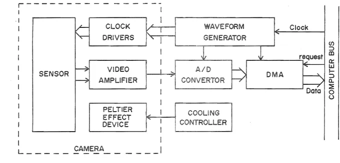
HI S CAMERA
This chapter describes the image capture sUbsystem developed for the High Resolution Image Processing System (HIPS).
NEED FOR A LABORATORY CAMERA
Almost all commercially available cameras are designed around
television rates. Television standards have been established in an attempt to make the system match the properties of the human perceptual system, especially with regard to the minimisation of flicker. This means that the maximum integration time is restricted to 20ms. Although this is adequate for many applications, in a laboratory situation it is desirable to have available a camera with a wide range of integration times.
Long integration times are necessary in astronomical applications where the low light levels preclude the use of conventional cameras (Hall, 1981). With distant objects, integration times in the order of hours may be necessary. At the other extreme, when imaging fast moving objects, short integration times may be necessary to prevent motion blur.
N (V)
r
-I ·1
I
I
SENSOR
CLOCK
DRIVERS
VIDEO
A
ER
PELTIER
EFFECT
DEVICE
CAMERA
ERATOR
/
R
-I
- - __ I
Figure 3.1: A block diagram of the HIPS image capture subsystem.
Clock
request
I
a:::
w
A
' .. I
I-::>
a..
:E
[image:55.841.81.762.103.430.2]