TECHNICAL UNIVERSITY OF CLUJ-NAPOCA
ACTA TECHNICA NAPOCENSIS
Series: Applied Mathematics, Mechanics, and Engineering Vol. 61, Issue II, June, 2018
SOLAR WATER HEATING FOR A SWIMMING POOL
Octavian POP, Ioan POP
Abstract: The paper presents the theoretical elements that led to the elaboration of the technical project of a solar hot water preparation plant for a swimming pool. The thermal calculation of the solar plant, as well as the simulation of its operation, based on the climatic parameters in Cluj-Napoca provided by the typical meteorological year is analysed. The results of the study indicate the amount of the domestic hot water produced by the solar collectors and its share from the daily requirements.
Key words:renewable energy, solar energy, solar panel, domestic hot water, building services.
1. INTRODUCTION
The paper presents the theoretical elements of the designing of a solar hot water preparation plant intended for an existing swimming complex owned by Babeş Bolyai University Cluj-Napoca, as well as the design elements of the solar installation. In order to reduce the energy consumption, the efficiency of the domestic hot water (DHW) preparation, during the warm season, using flat plate solar collectors is analyzed. The DHW heated by the flat plate solar collectors is used by the showers of the swimming complex.
2. PRESENT STAGE
The swimming pool’s heating plant consists of 3 boilers (3x1,200 kW). These boilers are used in the production of thermal agent that supplies the HVAC system as well as the preparation of the DHW used in the swimming pool and sanitary groups. At present, the preparation and accumulation of hot water is achieved by means of a 130 kW flat plate heat exchanger and a 2,000 liter storage tank.
In order to design the solar hot water preparation system, the calculation of the existing solution was performed during the academic year (October – June, cold period) and during the vacation (July – September, hot period). Atypically, considering the periods
when solar energy is available, the daily number of users during the cold season: 1,360 swimmers is much higher than in the summer 720 swimmers.
Table 1 presents the specific DHW requirements according to [1], as well as the mean values adopted for the preliminary calculations of existing equipment. Based on the data provided by the Babeş Bolyai University we were able to determine: the hot water consumption chart, the schedule of the thermal energies necessary for the DHW preparation, as well as the heat supplied by the flat plate heat exchanger and the amount of DHW that can be stored. It was concluded that the existing equipment of the heating plant can assure the demand DHW requirements.
Table 1
DHW - the specific requirements and daily consumption
Building type
Specific requirement [l/pers./day]
Daily consumption [l/day]
DHW
60°C
DHW
45°C
DHW
60°C winter
DHW
60°C summer
DHW
45°C*
summer Public
showers 30 43 40800 21600 30960 Sports
facilities 20 28 27200 14400 20160 Mean
value 25 35.5 34000 18000 25560
280
In the case of solar DHW preparation the considered temperature is: 45 °C and the specific demand 35.5 l/pers./day [2], resulting the values presented in table 1.
3. THE SOLAR GEOMETRY
In order to determine the value of the total solar radiation on a random surface, as well as the distance between the flat plate solar collectors the hourly coordinates of the sun must be calculated.
3.1The angle of incidence of the solar rays The apparent movement of the sun towards a steady observer located on the surface of the earth and characterized by its latitude: φ and longitude: λ, is necessary in order to calculate the following angles:
● solar declination angle [3]:
) 202 30 cos( 45 ,
23 ⋅ ⋅ + −
=
δ o m d ; [°] (1)
) 365 284 360 sin( 45 ,
23 o ⋅ ⋅ + n
=
δ ; [°] (2)
where: m – the number of the month; d – day of the month;
n – number of the day starting with the 1th. January;
● elevation angle of the sun:
) cos( cos cos sin sin )
sin(h = ϕ⋅ δ+ ϕ⋅ δ⋅ ω⋅τ* ;
) 12 ( 15
* = ⋅ τ −
τ ⋅
ω o
; [°] (3)
where: τ – hour of the day;
● angle of solar azimuth [3]:
A a =180o + ;
) cos( ) sin( cos sin cos ) cos( sin ) sin( * * * h A tg A τ ⋅ ω ⋅ δ − = → δ ⋅ ϕ − τ ⋅ ω ⋅ ϕ τ ⋅ ω =
; [°] (4)
To determine the angle of incidence of the solar rays, on a surface tilted with the angle α
from the horizontal plane, and oriented in southern direction indicated by the angle γ, the following relation as used [3]:
) cos( sin ) cos( cos ) sin(
cosβ = h ⋅ α+ h ⋅ α⋅ γ− A .
[°] (5)
3.2Distance between the solar panels
Depending on the dimensions of the area, in this case the available terrace, the type of flat plate solar collector (horizontal or vertical) is adopted, so that the maximum number of solar panels (SP) is assured. In this case, because of the constraints of the available terraces, vertical solar collectors have been adopted. Solar collectors should be positioned so that they do not shade each other during the spring-autumn period.
The length of the shade in the vertical plane containing the sun and the centre of the earth is determined with: α ⋅ + α ⋅ = cos ) ( sin SP SP l h tg l
l ; [m] (6)
where: lSP – length of the solar panel, [m].
Considering a southern orientation of the solar panel the length of the shade in the plane normal to the panel is obtained, using:
lshadow = l⋅cosa. [m] (7)
In the designed solar plant the following values were adopted: the length of the panel: lSP = 2.38
m, the angle of the collector from the horizontal plane: α = 45 °, that allowed for the determination of the length of the shade during an entire year.
Figure 1, presents the variation of the shadow length of the collector at 12:00. Consequently the adopted distance between the solar collectors is: 3.5 m, in order to ensure that the collectors do not shade each other, for a period of 20th March – 25th September.
Fig. 1.Variation of shadow length 0 1 2 3 4 5 6 7
0 30 60 90 120 150 180 210 240 270 300 330 360
L e n g th [ m ]
Day of the year
Length of the shade Distance between the collectors
3.3Calculation of solar irradiance
The calculation of the intensity of incident solar radiation on a tilted flat surface was performed based on the climatic data from the typical meteorological year (TMY), taking into account the orientation of the collectors and the elements of solar geometry.
The TMY indicates the values of the direct solar radiation on a horizontal plane Idir O, in
[W/m2] and diffuse solar radiation on a horizontal plane Idif O, in [W/m2].
The total intensity of incident solar radiation on the surface of the solar collectors, is determined by the direct and diffuse solar radiation, noted as Idir , in [W/m2] and Idif , in
[W/m2] respectively, taking into account the location and orientation of the collectors:
2 cos 1 )
sin(
cos + α
⋅ + β ⋅
= dirO difO
t I
h I
I [W/m2]. (8)
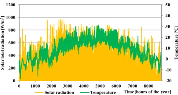
Figure 2 presents the ambient temperature variation and the variation of the incident solar radiation intensity according to the TMY, considering a southern orientation of the collector: γ = 0°, and tilted at: α = 45°.
Fig. 2. The variation of the ambient temperature and total incident solar radiation on the solar collector
The efficiency of the flat plate solar panel is defined as the ratio between the density of thermal flux stored in the heat transfer fluid
(HTF):qu
.
, [W/m2] and the total intensity of solar radiation [3]:
t air mf t p t p t t u SP I t t I q I q I I q − Φ − Φ = − = − = =
η 1 2
. .
.
1
[-, ·100 %] (9)
where: qp
.
- density of thermal flux released to
the ambient air, [W/m2];
Φ1 – characterizes the absorption capacity of the
panel;
Φ2 – characterizes the heat losses to the
environment through the external surface of the panel.
Equation (9) yields the following form [4]:
t air mf o SP I t t k ⋅ − −
η =
η ; [-, ·100 %]
or a more precise relation [4]:
(
)
t air mf t air mf o SP I t t k I t t k 2 2 1 − ⋅ − − ⋅ − η = η ;[-, ·100 %] (10)
where: ηo – optical efficiency of the solar panel: ηo = 77,5-84 % [4], [5];
k – global heat transfer coefficient of the external surface per unit surface area, [W/m2·K], k = 2÷4 W/m2·K [4], [5];
k1, k2 – coefficients that take into account the
heat losses to the external environment, [W/m2·K], k1 = 3.36÷4.16 W/m2·K, k2 =
0.0073÷0.013 W/m2·K, for flat thermal panels [4], [5];
tmf – mean temperature of the HTF – water +
ethylene/propylene glycol, [°C]; tair – ambient air temperature, [°C].
Adopting the average heat transfer fluid temperature involves the analysis of the operation of solar hot water plants, taking into account the random nature of solar radiation as well as the unsteady heat transfer. Under normal operating conditions, the pump starts circulating heat transfer fluid if the temperature difference between the panel temperature and hot water temperature in the tank is within the range of: 8 ÷ 10 ° C.
The pump stops circulating heat transfer fluid when there is a difference in panel temperature and hot water temperature of 2 ° C.
Thus the efficiency of the collector is determined considering a mean value of the heat transfer fluid’s temperature in the range of: tmf =
53÷55 °C, a value which exceeds the DHW operating temperature with 8÷10 °C [2]. -20 -10 0 10 20 30 40 50 0 200 400 600 800 1000 1200
0 1000 2000 3000 4000 5000 6000 7000 8000
T e m p e ra tu re [ ° C ] S o la r to ta l r a d ia ti o n [ W /m 2]
282
During the absence of solar radiation, or during periods when the intensity of solar radiation is reduced, the efficiency of the collector calculated with relation (10) assumes negative values. Therefore during these periods the efficiency is considered ηSP =0.
3.4The effective HTF temperature
In the absence of solar radiation, the temperature of the solar collectors and of the HTF is considered equal to the ambient temperature, as thermal equilibrium is reached. In the presence of solar radiation, but in the case where the intensity of solar radiation is reduced (logical test ηSP =0), the preheating of
the HTF contained within the flat plate solar collector takes place. In this situation the circulation of the HTF stagnates.
The effective temperature of the HTF from the solar collectors teff, is determined by solving
equation (10), that yields a unique solution for
ηSP =0:
2
2 2
1 1
2 4
k
k I k
k t
teff air o t
⋅
⋅ ⋅ η ⋅ + + − +
= .[°C](11)
respecting the condition: teff < tmf .
If the effective temperature of the HTF reaches or exceeds the value of the mean temperature of the HTF: teff ≥ tmf, the pump is
turned on. This implies the calculation of the amount of solar heated DHW. In the case of a high intensity in solar radiation the efficiency of the collector is ηCSP> 0, and the calculation of
the amount of produced DHW is carried out.
3.5The amount of DHW
The determination of the amount of DHW: mDHW [kg/h] that can be prepared over a period
of time: ∆τ = 3600 s, is carried out on the basis of the energy conservation law, according to the relation:
(
)
(
DHW CW)
DHW
SPl SP SP SP t DHW
CW DHW DHW DHW SPl
SP SP SP t
t t c
n S I m
t t c m n
S I
− ⋅
η ⋅ η ⋅ ⋅ ⋅ ⋅ τ ∆ =
⇒ − ⋅ ⋅ = η ⋅ η ⋅ ⋅ ⋅ ⋅ τ ∆
[kg/h] (12)
where: SSP – the surface area of a solar panel,
[m2]:
nSP – number of solar panels: 3*19 constrained
by the available space;
ηSPl – overall efficiency of the solar plant,
considering the heat losses to the environment through thermal insulating layers of the pipe system and heat losses of the flat place heat exchanger. The efficiency is estimated at: ηSPl =
94÷96 %;
cDHW – specific heat capacity of DHW, [J/kg·K];
tCW – temperature of cold water (CW), in [°C],
adopted as tCW = 5,5 °C and tCW = 12,5 °C,
during the cold season and hot season respectively.
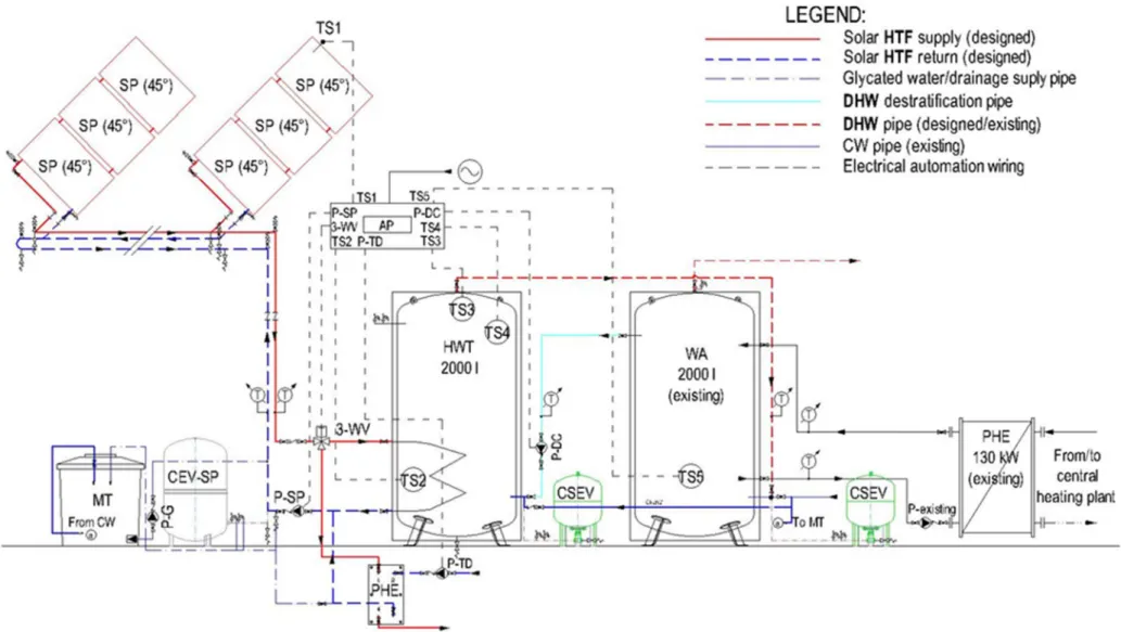
4. SOLAR PLANT FOR DHW PREPARATION
The solar hot water plant designed for the swimming pool is shown in figure 3 and has the following components:
a. Plate solar panel
The solar panels are mounted on the terrace roof of the swimming pool in the area of the auxiliary spaces. The configuration of the roof allows the mounting of a total number of solar panels: 19 rows * 3 panels / row, oriented to the south.
The rows of solar panels are connected to the distribution by: elastic connections allowing free expansion, isolation valves, provided with manual air vent valves at the highest points, and drainage valves. The distribution of the HTF made from the copper pipe is in the Tichelmann loop, which ensures the hydraulic balancing of the solar plant. The ends of the distribution are equipped with: isolation valves, drainage valves, air vent valves.
The distribution pipes are equipped with expansion axial compensators. The copper pipes of the distribution are insulated with semirigid shells made of polyurethane or basalt mineral wool casted with aluminum foil and protected from the exterior with a barrier of polyethylene foil and galvanized steel sheet.
b. Solar DHW preparation
2
8
3
284
based on the thermal energy supplied by the solar panels.
The solar DHW plant within the central heating system has the following circuits:
• Solar panels - HWT
The supply and return circuit made of copper pipes are equipped with:
- variable speed circulation pump of the solar plant (P-SP);
- 3-way motorized valve (3WV), with on/off system, which allows thermal discharge in case of overheating of HTF;
- closed expansion vessel for the solar plant (CEV-SP) with elastic membrane that allows the dilatation of glycated water from solar panels;
- closed sanitary expansion vessel (CSEV).
• HWT – existing water accumulator (WA) destratification circuit
The destratification circuit is equipped witch a variable speed circulation pump of the destratification circuit (P-DC), to ensure the storage of hot water in both tanks.
● Glycated water supply circuit
The glycated water from the solar system is obtained by mixing: softened water (supplied by the thermal plant softening station): 60 % with ethylene/propylene glycol 40 % in the mixing tank (MT). A filling pump is used to supply the system with glycated water (P-G).
c. The thermal discharge installation
During periods when the consumption of domestic hot water is low, in order to avoid overheating of the glycated water from the solar plant, thermal discharge takes place through a plate heat exchanger using the water from the thermal plant of the swimming complex as secondary HTF.
During the summer, in the vacation period maintenance and reparations of the thermal plant and HVAC system are carried out. In order to avoid overheating of the solar panels during this period (15-20 days) the panels are protected with radiation resistant blinders.
d. The automation panel (AP) of the DHW For the efficient operation of the solar hot water preparation plant, its operation will be controlled by an automation board, which must satisfy the following functions:
● Automatic preparation of solar DHW
The automation controls the operation of the solar circuit pump P-SP based on the temperature difference between the temperature of the solar panel and the HWT temperature (∆t), as measured by the temperature sensors (TS) TS1 and TS2. P-SP starts when ∆t = 8 °C. Pump flow is modulated according to temperature difference:
- ∆t = 8 °C→ 30 % nominal flow rate; - ∆t=10 °C→ 40 % nominal flow rate; - ∆t=20 °C→ nominal flow rate. P-SP stops when ∆t < 8 ° C.
● Charging of WA
Automation orders the charging of the HWT and the existing WA as follows:
- P-DC starts at ∆t = 15 °C, the temperature difference between TS4 and TS5;
- P-DCstops when ∆t < 5 °C;
● Automation of thermal discharge of the solar installation
The automation controls the start of the thermal discharge at the maximum allowed temperature of the HWT determined by the temperature limiter TS 3 - set at 90 (95) ° C.
The automation orders:
- the position of the 3-way motorized valve in the direction to the plate heat exchanger (PHE); - the operation of P-SP at nominal flow rate; - the operation of the discharge pump P-TD.
Thermal discharge stops when the HWT water temperature drops below the maximum allowed temperature difference generally set at:
∆t = 10 °C.
The automation orders:
- the position of the 3-way motorized valve in the direction to the HWT;
- the shutdown of P-TD;
difference measured by temperature sensors TS1 and TS2.
● Preparation of DHW without solar input During the periods without solar radiation, the DHW is prepared by the existing boilers of the thermal plant, the operation being ensured by the existing automation.
In periods of moderate consumption, the DHW is prepared by the existing plate heat exchanger PHE (130 kW) and is accumulated in the WA. During these periods, the HWT and P-DC are not operating.
During peak periods, if the demand for hot water exceeds the existing capacity of the PHE (130 kW) and the existing capacity of the WA, it is possible to also accumulate DHW in the HWT by turning on the destratification pump.
In periods of low solar input, it is possible to preheat the hot water consumption on the basis of solar radiation. The operation of solar DHW preparation is controlled by the temperature difference ∆t - between the solar panel temperature sensor TS1 and the temperature sensor on the HWT TS2 which controls the solar panel pump P-SP.
5. RESULTS AND CONCLUSION
Based on the theoretical elements presented above, a program has been developed to simulate the operation of the solar plant for DHW preparation. The climatic data for Cluj-Napoca was taken from the TMY.
The amount and share of solar prepared DHW during the hot period are resented in figures 4 and 5 respectively.
Fig. 4. Amount of DHW produced by the solar collector during the hot season
Fig. 5. Share of solar prepared DHW from the total amount of DHW demandduring the hot season
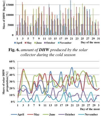
The amount and share of solar prepared DHW during the cold period are resented in figures 6 and 7 respectively.
Fig. 6. amount of DHW produced by the solar collector during the cold season
Fig. 7 share of solar prepared DHW from the total amount of DHW demand during the cold season
The results of the simulation indicated a reduction in energy consumption for the production of DHW as follows:
- during the spring: 25.03 ÷ 30.68 % (April – June);
- during the summer: 38.32 ÷ 46.89 % (July and August);
- during autumn: 12.46 ÷ 29.32 % (September and October).
0 5000 10000 15000 20000
1 3 5 7 9 11 13 15 17 19 21 23 25 27 29 31
M
a
ss
o
f
D
H
W
[
k
g
/d
a
y
]
Day of the month
July August September
0% 10% 20% 30% 40% 50% 60% 70% 80%
1 3 5 7 9 11 13 15 17 19 21 23 25 27 29 31
S
h
a
r
e
o
f
so
la
r
D
H
W
p
r
e
p
a
r
a
ti
o
n
[
%
]
Day of the month
July August September
0 5000 10000 15000 20000
1 3 5 7 9 11 13 15 17 19 21 23 25 27 29 31
M
a
ss
o
f
D
H
W
[
k
g
/d
a
y
]
Day of the month
April May June October November
0% 10% 20% 30% 40% 50% 60%
1 3 5 7 9 11 13 15 17 19 21 23 25 27 29 31
S
h
a
r
e
o
f
so
la
r
D
H
W
p
r
ep
a
ta
ti
o
n
[
%
]
Day of the month
286
The maximum amount and share of solar prepared DHW is limited by the surface area of the roof which determines the number of solar panels.
6. REFERENCES
[1] *** I 9-2015, Normativ privind proiectarea,
execuţia şi esploatarea instalaţiilor sanitare aferente clădirilor, 2015.
[2] *** STAS 1478-90, Alimentarea cu apă la
construcţii civile şi industriale Prescripţii fundamentale de proiectare, 1990.
[3] Fara, V., Grigorescu R., Conversia energiei solare în energie termică Principii şi aplicaţii, Bucureşti, Editura Ştiinţifică şi Enciclopedică, 1982.
[4] Balan, M., Energii regenerabile, Cluj-Napoca, UT Press, 2007.
[5] https://www.viessmann.com/com/en.html.
Prepararea solara a apei calde pentru un complex de nataţie
Rezumat: Lucrarea prezintă elementele teoretice care au stat la baza elaborării proiectului tehnic al unei instalaţii solare de preparare a apei calde de consum pentru un Complex de nataţie. Ȋn lucrare este sintetizat calcul termic de dimensionare a instalaţiei solare, precum si simularea functionarii acesteia pe baza parametrilor climatici din Cluj-Napoca furnizaţi de anul climatic standard. Rezultatele studiului indică cantitatea de apă caldă de consum preparată solar şi ponderea acesteia din necesarul zilnic, ceea ce indică economia de combustibili convenţionali.
Octavian POP, Eng., PhD Student, assist. professor, Tehnical University of Cluj-Napoca, Department of Mechanical Engineering, E-mail: [email protected], Home Phone no.: 0744767254.
![Table 1 presents the specific DHW requirements according to [1], as well as the mean values adopted for the preliminary calculations of existing equipment](https://thumb-us.123doks.com/thumbv2/123dok_us/7998122.2120666/1.892.492.840.913.1126/presents-specific-requirements-according-preliminary-calculations-existing-equipment.webp)
![Fig. 1. Variation of shadow length 012345670306090120150180210240270 300 330 360Length [m]](https://thumb-us.123doks.com/thumbv2/123dok_us/7998122.2120666/2.892.448.786.922.1109/fig-variation-shadow-length-length-m.webp)