An Information Management Protocol
to Control Routing and Clustering
in Sensor Networks
Marzieh Veyseh, Belle Wei and Nader F. Mir
San Jos´e State University, SADThis paper develops and analyzes a novel clustering protocol, the Decentralized Energy Efficient cluster Propagation(DEEP)protocol that manages the
commu-nication of data while minimizing energy consumption across sensor networks. The paper also presents an Inter-Cluster Routing protocol(ICR)that is compatible
with the proposed clustering technique. The DEEP protocol takes advantage of the multi-rate capabilities of 802.11a, 802.11b, and 802.11g technologies by elevating the data rate to higher levels for shorter transmission ranges. This approach reduces the energy consumption by lowering the transmission time. In order to conserve energy and prolong network lifetime, the DEEP protocol starts with an initial cluster head and gradually forms clusters throughout the network by controlling the di-mension of clusters and the geographical distribution of cluster heads. Because this model results in a balanced load among cluster heads, protocol overhead due to frequent re-clustering is eliminated. Simulation results demonstrate that the DEEP protocol distributes energy consumption approximately eight times better than the LEACH protocol-clustering scheme. In addition, the DEEP protocol substantially reduces total data com-munication and route setup energy consumption in the network compared to the LEACH protocol.
Keywords: information processing for sensors, routing protocol, network management, clustering in sensor network, energy management.
1. Introduction
Advances in semiconductor technologies and wireless communication make the deployment of a network of ubiquitous tiny sensor nodes possible. These self-configuring sensor net-works can gather comprehensive information about a large geographical area or about move-ments of an object for surveillance purposes.
Target tracking, environmental monitoring, sys-tem control, and chemical/biological detection
are some of the possible applications12]. A
sensor’s small physical size implies limited space for a battery. The high density and random dis-tribution of sensors make it impossible to peri-odically recharge or exchange batteries. As a result, it is critical to use energy-efficient algo-rithms to prolong the life of sensor networks. Energy-aware protocols have been developed exclusively for wireless sensor networks1-11]
in medium access control(MAC), routing, and
clustering which specifies the network topol-ogy. Most of the proposed energy-aware MAC protocols aim to use one of the two methods for reducing communication energy: adjust-ing the transmission power6], and keeping the
transceiver off as long as possible11].
Clustering algorithms specify the topology of a hierarchical network that is partitioned into non-overlapping clusters consisting of neigh-boring nodes. Each cluster has a cluster head; communication among nodes or with a central base station is through this cluster head. Since every node in a clustered network is connected to a cluster head, the route discovery process among cluster heads is sufficient to establish a feasible route in the network. For a large sensor network, clustering can simplify the multi-hop route discovery process and limit the number of transmissions compared to a flat, non-clustered network. The added overhead is the formation and maintenance of clusters.
algo-rithms require each sensor node to send its in-dividual information(such as energy level and
geographical position) to the central base
sta-tion. Based on a predefined algorithm, the base station then calculates the number of clusters, their sizes, and the cluster heads’ positions, and informs each node of its newly assigned duty1], 2]. Given the assumption that sensor networks
consist of thousands of nodes, it is impractical, if not impossible, for the base station to collect information about every single node in the net-work prior to the route setup phase. Therefore, centralized clustering is not an option for large sensor networks.
Decentralized clustering techniques create clus-ters without the help of any centralized base station. Bandyopadhyay and Coyle 6]present
an energy efficient hierarchical clustering algo-rithm where each sensor node becomes a cluster head with a probability of p and advertises its candidacy to nodes that are no more thank-hops away from the cluster head. Given the limited transmission range of wireless sensor nodes, a hierarchical structure with an arbitrary number of levels has its limitation. As the number of hierarchical levels grows, it is possible that the distance between upper-level cluster heads in-creases to the point that they are no longer able to communicate with one another. The Max-Min d-Clustering 7] algorithm creates d-hop
clusters, but there is no consideration for en-ergy optimization. The Low Enen-ergy Adaptive Clustering Hierarchy(LEACH)algorithm9]is
another decentralized clustering algorithm that does not offer a complete energy optimization solution as it has no strategy for specifying clus-ter heads’ position and distribution.
For cluster-based routing protocol, both inter-cluster and intra-inter-cluster routing protocols have been developed to keep the network connected. Assuming that all sensors can act as a relay node, there could be a large number of possible routes from one data source to the sink. To find the proper path, two major approaches can be used:
Centralized route selection algorithm. Distributed route selection algorithm, which is classified into two main categories:
Proactive routing Reactive routing
Centralized route selection algorithms aim to choose the appropriate next neighbor for each node using a central command node. The cen-tral command node collects the information about direct paths’ cost and geographical po-sition of the nodes and finds the least cost path using shortest path algorithms such as Dijk-stra 20]. CSEAR is a protocol proposed in 21]that chooses TDMA along with centralized
routing to minimize energy consumption. On the other hand, wireless networks that perform distributed routing leave the route selection de-cision to the sensor nodes by themselves. Nodes with proactive route selection algorithms such as link state routing and distance vector rout-ing20]keep a routing table that contains next
hop information to every single node in the net-work. Reactive routing protocols set the route to the desirable destination only when it’s needed. For Ad-hoc wireless networks, Dynamic Source Routing(DSR)and Ad-Hoc On-Demand
Vec-tor Routing (AODV) are the examples of
re-active routing 17]. But none of these
proto-cols consider the crucial energy consumption consideration introduced in wireless sensor net-work.
Another group of on-demand reactive routing protocols have been proposed to address the ex-clusive issues of wireless sensor network. SPIN
22] and Directed Diffusion 23] introduce a
concept of “interest” propagation whenever a node wants to send data or a source needs to ask for it. Flooding the network with interest signals will establish a path from a sink to every possible source(spanning tree). While directed
diffusion reinforces the paths with higher data rate, SPIN concentrates exclusively on the path set up via negotiation.
To summarize, both energy conscious clustering and routing algorithms should reduce energy consumption, balance the load among sensor nodes, and prolong network lifetime. This pa-per proposes a Decentralized Energy-Efficient cluster Propagation(DEEP)protocol that
heads. The remainder of this paper is organized as follows. Section 2 describes the communica-tion energy model used for this paper. Seccommunica-tion 3 introduces the DEEP protocol and states its advantages. Section 4 presents an inter-cluster routing protocol. Section 5 evaluates the per-formance of the protocol and compares it with a general version of the LEACH protocol.
2. Communication Energy Model
2.1. Energy Model for Multi-Rate 802.11
Recent advancements in the area of wireless local area networks have led to the develop-ment of today’s popular IEEE standards such as 802.11a, b, g. These standards have been widely adopted by consumers and provide the widest possible range of data rates of 54, 48, 36, 24, 18, 12, 9, and 6 Mbps reflecting the trade-off between the transmission range and data rate intrinsic in a wireless communication channel. An accurate energy model is cru-cial for the development of an energy efficient clustering and routing protocols. The popular energy model of ωdn cannot properly demon-strate the energy consumption versus transmis-sion distance for wireless communication. In general, all transceiver energy components are summarized as:
E(Watt)
=θ +ηampωd
n
(1)
whereθ is a distance-independent term that ac-counts for the overhead of the radio electronics and digital processing and ω models the free space path loss 15]. Based on
environmen-tal conditions, n could be a number between 2 and 4. ηamp represents the amplifier ineffi-ciency factor and specifies the ineffiineffi-ciency of the transmitter when generatingωdn power at the output of the antenna. The effect that a distance-dependent term has on the total en-ergy consumption depends on the real world transceiver parameters, θ, ηamp, and the path attenuationωdn. If the value ofθ overshadows ηampωd
n, then the reduction in the transmis-sion distance through the use of multi-hop com-munication is not effective 15]. The Atheros
2004 tri-mode chipset 14] is used to monitor
the real values for the radio hardware. In theory, the maximum efficiency of a power amplifier
is 48.4%. However, practical implementations show that the power amplifier efficiency is less than 40% 19]. Therefore, θ is calculated
us-ing the assumption thatηamp =(1=0:4=2:5).
While maximum output power and total power consumption is provided in the manufacturer data sheet, θ could be calculated based on the following formula:
θ =θTX+PRX
=(PTX ;ηampωd
n
)+PRX (2)
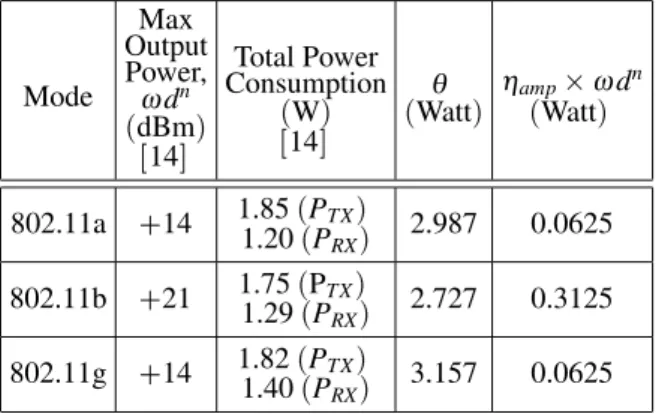
Table 1 shows the values forPTXandPRX based on the manufacturer’s data sheet and the values forθ andηampωd
ncalculated for the chosen chipset. Despite the fact that the path attenua-tion energy increases exponentially by the trans-mission distance, the data illustrates that static power consumption(θ)dominates the path loss
and, therefore, causes the total power consump-tion to remain constant as transmission distance increases.
Mode Max Output Power,
ωdn
(dBm) 14]
Total Power Consumption
(W) 14]
θ
(Watt)
ηamp ωdn
(Watt)
802.11a +14
1.85(PTX)
1.20(PRX)
2.987 0.0625 802.11b +21
1.75(PTX)
1.29(PRX)
2.727 0.3125 802.11g +14
1.82(PTX)
1.40(PRX)
3.157 0.0625
Table 1.Energy Consumption Parameters for Atheros2004 tri-mode chipset. Rate
(Mbps)
Max.
Range (MbpsRate)
Max. Range
1 100 m 18 51 m
2 76.5 m 24 41.25 m 6 64.5 m 36 36 m
9 57 m 48 23.1 m
12 54 m 54 18.75 m Table 2.Expected data rate of 802.11g technology13].
802.11g are some of the wireless networking standards that have multi-rate capabilities13].
Although sensor nodes in general generate data in low rates, they can transmit the information using wireless high-speed modulation and tech-niques. Table 2 shows the expected data rate for 802.11g wireless technologies. While exploit-ing the multi-rate capabilities of wireless stan-dards has never been proposed for sensor net-works, this technique can decrease the transmis-sion energy for smaller distances by switching to higher data rates and keeping the transceiver on for a shorter period of time.
EJoule=bit =
(θ+ηampωd
n
)Joule =sec
(Rate)bit =sec
(3)
In this case, energy in terms of Joule/bit reduces
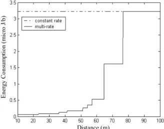
discretely as transmission distance shrinks. Fi-gure 1 shows the energy consumption of Athe-ros2004 radio for 802.11g technology at the constant rate of 1Mbps and the same technology with the multi-rate extension.
As Figure 1 illustrates, due to the large value ofθ compared to maximum output power, sin-gle rate communication energy consumption remains constant as transmission distance in-creases while communication energy consump-tion for multi-rate transmission decreases for shorter transmission ranges. However it does not follow the model ofωdn. Meanwhile, multi-rate communication would necessitate the pres-ence of a robust rate selection protocol.
Fig. 1.Energy consumption versus transmission distance for single rate and multi-rate communication
(802.11g technology).
2.2. Multihop Communication Efficiency
Considering the real world radio parameters and multi-rate communication impacts, we should re-evaluate the effectiveness of multihop com-munication. Since multi-rate communication reduces energy consumption for shorter dis-tances by switching to higher data rates, multi-hop can conserve energy. The traditional ob-jective of multihop communication is to divide the transmission distance intomsmaller ranges
(m represents number of hops) and relatively
conserve energy considering Equation (1) by
means of15]:
E=m(θ +ηampω(d=m)
n
) (4)
However, if division of transmission distance happens when maximum range is less than 18.75 m for 802.11g, data rate remains constant and total energy consumption multiplies by number of hops. Since sensor networks deal with 2 or even 3-dimensional spaces, the efficiency of multihop heavily depends on the scales and the density of the network. To investigate the effi-ciency more thoroughly, Figure 2 shows an or-ganization where sensor nodes are placesd me-ters away from each other, and they tend to send their data packet to the Cluster-Head(CH). We
assume that 802.11g technology is being used in this environment. dis an application-dependent parameter and can be chosen based on the sen-sor’s characteristics. It is predicted that for toxin detections, sensors should be placed in average no more than 10 m away from each other. With the choice of 10 m ford, if node B tries to use node A as a relay node and send the data to the
CH, total energy of the chosen 2-hop path will be larger than the direct transmission energy:
E( p
2d)=0:0517
<E(d)+E(d)=0:1034 (5)
Also, for nodes C and D, there is no multihop path that can lead to better energy consumption than the direct communication path:
E( p
5d)=0:0581 <E(
p
2d)+E(d)=0:1034 (6)
E( p
10d)=0:0775 <E(
p
5d)+E(d)=0:1098 (7)
But if node E first sends the data to the interme-diate node D, total energy consumption will be less than the direct communication path:
E( p
17d)=E(41:23)=0:1789 >E(
p
10d)+E(d)=0:1292 (8)
Node E is placed 41.23 m away from the cluster head. This shows that for nodes that are placed more than 41.23 m away from each other, di-rect transmission is no more the best possible communication method. In order to compare the energy consumption of direct and multihop communication inside the cluster, we set up an environment representing one cluster. The di-mension of the field is 50 m50 m, and 25 nodes
Fig. 3. Communication energy versus distance form cluster head for 802.11g technology.
are randomly dispersed in the field. At this point, we assume that cluster head is chosen ran-domly among the sensors; later details of cluster head selection algorithm will be explained. Fig-ure 3 shows the energy consumption of direct, minimum energy 2-hop, and minimum energy 3-hop path based on the distance between nodes in the cluster and the cluster head. For 802.11g technology, direct transmission is the optimum choice for ranges less than 37 m, which is al-most the same as the result from analytical cal-culations(41 m). However, for ranges greater
than 37, minimum energy 2-hop path can lead to significantly lower energy consumption.
3. Proposed Energy-Efficient Clustering Protocol
3.1. Cluster Head Positioning
Based on the results obtained in Section 2.2, for nodes that are placed more than 37 m away from cluster head, a strong path selection algorithm is necessary in order to find the optimum 2-hop or 3-hop path. While direct transmission can elim-inate the overhead caused by route setup con-trol messages, its efficiency is limited in terms of transmission range. In order to avoid the frequent control signal transmission and extra power consumption associated with that cluster head could be placed at the center of the cluster, while sensor nodes are positioned closer than
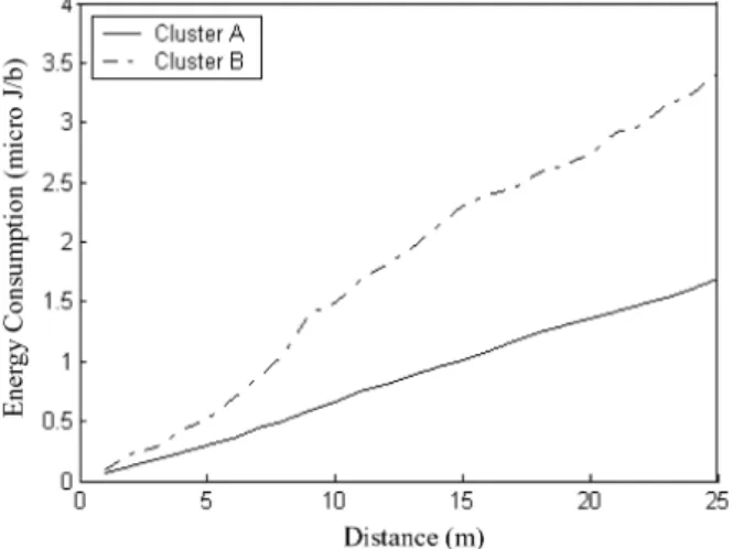
Fig. 4. Cumulative communication energy between sensor nodes and the cluster head versus distance form
37 m around it. In this case, cluster members can send the data packets directly to the clus-ter head without the need for any route set up protocol, while efficiency is already achieved through the choice of cluster shape and cluster size. Figure 4 compares two different clusters of the same dimension. A is a cluster with the cluster head being positioned at the center, and
Bis a cluster with the chosen cluster head in the corner. The cumulative energy consumption that the centered positioned cluster head should spend to receive one bit of information from all the members is significantly lower than the cu-mulative energy in the cluster head positioned in the corner.
3.2. Protocol Details
A robust clustering technique is essential in or-der to configure clusters with almost the same radius and cluster heads that are positioned in the center of clusters. Since sensor nodes be-gin without any knowledge about their location relative to the base station, distributed cluster-ing algorithm should be able to form clusters without the help of base station and knowledge of network member’s position. Although loca-tion finder devices and protocols could be de-ployed, they are either costly or put too much overhead on the network. DEEP is based on the idea of starting with an initial cluster head and forming new cluster head candidates grad-ually by controlling relative distance between a pair of cluster heads and circular radius of each cluster. Due to the balanced load among cluster heads(will be shown in Section 5.1),
pe-riodic re-clustering is not necessary and there-fore operational expenses caused by frequent re-clustering is eliminated. In order to explain the details of this algorithm, first we introduce control signals and protocol parameters: Control signals:
Cluster Head(CH)declaration signal
Cluster Head(CH)exploration signal
Membership search signal Control Parameters:
Declaration range(dr)
Exploration range(er1,er2)
Minimum number of members(mn)
Erc1andErc2
Protocol control parameters are application spe-cific choices and can be defined prior to the net-work deployment. Protocol DEEP forms clus-ters by starting with an initial cluster head that can be chosen prior to the network deployment. This initial cluster head starts the cluster set up phase by propagating cluster head declaration signal within the range ofdr. This means that cluster head candidate chooses the appropriate data rate and signal output power so that it can reach nodes that are less thandr away from the sender. At this point sensor nodes that receive the declaration signal accept the corresponding cluster head as a leader. They can estimate their relative distance to the candidate by look-ing at the received signal energy level. Once they know the relative distance to the cluster head, they can conserve energy by adjusting the transmission speed to the appropriate value and switching to the sleep mode. Now initial cluster head candidate propagates the cluster head ex-ploration signal within the range ofer2(Figure
5). All the sensor nodes that are in this range can
listen to the exploration signal, but only nodes that have never played the role of a cluster head and can verify the following inequality will be chosen as a new candidate:
Er >Erc2 & Er <Erc1 (9)
Eris the received signal energy and it should be bigger than Erc1 and smaller than Erc2 so that the node can consider itself as a candidate. This ensures that new cluster head candidates are po-sitioned betweener1(m)ander2(m)away form
the initial cluster head. Erc1andErc2are fixed protocol parameters that can be pre-calculated
Fig. 5.Initial cluster head starts the advertisement process. New cluster head candidates send the exploration signal within the range of er2to continue the
and stored in the sensor node memory using the following formula:
Erc1=Pout ;ω(er1)
n
(10)
Erc2=Pout ;ω(er2)
n
(11)
Pout is the constant output power of the clus-ter head exploration signal, and ω and n are parameters that can be determined based on the environmental conditions of the deployment area. After new cluster head candidates are as-signed, each candidate sends a declaration sig-nal within the range of dr to find new cluster members. If two candidates could hear the dec-laration signal of each other, they are too close to each other to be considered both as cluster head candidates. Therefore one of them will be eliminated through negotiation, i.e. when-ever a cluster head receives a declaration signal, it informs the sender of the message using an acknowledgement message. The cluster head that receives the acknowledgment sends a dis-solution message and informs all nodes within the range ofdr about its elimination. If a node receives declaration signal from more than one candidate, it chooses the candidates whose as-sociated signal is received with higher power. Then, confirmed cluster heads propagate explo-ration signal and search for new cluster head candidates. Nodes that have already been cho-sen as cluster head or member ignore the cluster head exploration or declaration signals. There-fore, this advertisement process will terminate automatically when all the nodes in the field belong to a cluster. At this point, algorithm might have produced some clusters with very small number of members. Therefore, if there is a cluster that its total number of members is smaller than “Minimum number of members”
(mn), cluster will be dissolved and all the
mem-bers including cluster head initiate a Member-ship search signal.
Afterwards, they listen to the responds from the local cluster heads and choose the closest clus-ter head based on the received signal power. At the end, ift =timeoutand a sensor node hasn’t
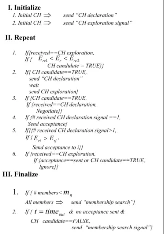
received any control signal, it sends a mem-bership search signal and chooses the closest cluster head as a leader. Figure 6 shows the pseudo-code for the DEEP protocol. Protocol execution can be summarized as follows: 1. Initial cluster head finds cluster members by
sending “cluster head declaration”.
2. Initial cluster head finds new cluster head candidates by sending “cluster head explo-ration signal”.
3. Cluster head candidates that are placed on the(er1,er2)ring find cluster members.
4. Nodes that receive more than one cluster head declaration choose the closest cluster head based on the received signal energy. 5. Cluster head candidates that receive cluster
head declaration signal negotiate with the sender, and one of them gets eliminated. 6. Confirmed cluster heads send “cluster head
exploration’ to find new cluster head candi-dates(go to 4).
7. If the number of members in a cluster is less than mn, all the members find new clusters by sendingmembership search signal.
8. At the end, if a node has not received any control signal, it sends membership search signal.
The protocol provided in this paper has the fol-lowing advantages:
As it was discussed, DEEP is a completely decentralized protocol. A sensor node can either elect itself as a cluster head by receiv-ing a cluster head exploration signal or join a cluster by receiving a cluster head declara-tion signal.
After the execution of DEEP, all the sensor nodes are covered and belong to only one cluster.
For the execution of DEEP, there is no need for any location finder hardware such as GPS
(Global Poisoning System), or a position
es-timation protocol that puts extra overhead on the sensor nodes.
DEEP can control the cluster head distribu-tion across the sensor network through the protocol execution methodologies. These tactics include: cluster head candidates should receive the cluster head exploration signal with the certain amount of energy, and if they can hear the declaration signal of each other, one of the candidates will be eliminated. Communication cost is minimized via proper selection of protocol parameters (
declara-tion range, exploradeclara-tion range, and minimum number of members).
Intra-cluster communication is controlled by cluster heads, and nodes transmit their data directly to the cluster heads. Therefore, there is no additional control signal exchange as-sociated with route selection and mainte-nance inside the cluster.
Due to the uniform distribution of cluster heads, communication cost of a direct trans-mission path between a pair of neighboring cluster heads is almost identical across the sensor field. This is one of the most im-portant characteristics of this protocol that contributes tremendously to the ease of de-ployment of the inter-cluster routing proto-col.
4. Inter-Cluster Routing Protocol
After establishing well-distributed cluster heads and clusters in the network, energy conscious
routing is essential in order to set communica-tion routes among cluster heads in a two level hierarchical system. Due to the limited trans-mission range associated with low power wire-less technologies, cluster heads’ data packets cannot reach to the base station unless other cluster heads act as relay nodes. In this section, we propose an Inter-Cluster Energy Conscious Routing(ICR)protocol that is compatible with
the proposed clustering protocol. ICR uses in-terest flooding similar to directed diffusion23]
and Energy Aware Routing (EAR) 18] to
es-tablish routes between the base station and sen-sor nodes, but it differs from EAR and directed diffusion in some aspects. First we describe the ICR scheme and then accentuate the differences from EAR.
4.1. Routing Protocol Details
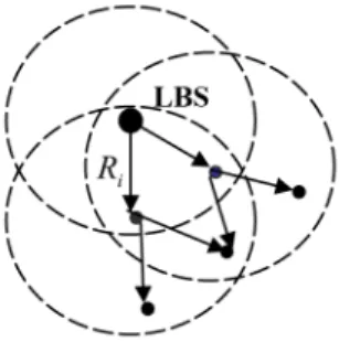
The protocol ICR is a destination-initiated reac-tive routing protocol. This means that a destina-tion, which we call Local Base Station(LBS),
initiates an explicit route discovery phase. This initiation includes propagation of an interest
signal that floods throughout the network and establishes energy efficient routes for the sake of data communication. Based on the applica-tion, which can be either periodic data collection or event driven, theInterest signal can include thetypeand theperiodof the desired data. For application that necessitates information from specific locations, interest signal also includes the position of the required information.
If the LBS requires some periodic data collec-tion phases, it sets the period in which nodes send that specifictypeof information. Monitor-ing and surveillance application are examples for data collection paradigm. If the LBS re-quires sensor nodes to detect one specific event, it includes the type of the event in the inter-est signal(Figure 7). Following the route
dis-covery phase, sensor nodes switch to the sleep mode and wait for the specific event. In case of event detection, non-cluster head nodes send the data directly to the associated cluster head,
and that cluster head uses the previously estab-lished route to send the information back to the LBS. We can explain the ICR execution in the following steps:
4.2. Route Discovery Phase
1. The LBS initiates the route discovery by sending an interest signal within the range of Ri. Ri should be high enough to keep the cluster head network connected and low enough to prevent unnecessary energy con-sumption and interest generation. Due to the even distribution of cluster heads achieved by clustering protocol, Ri can be chosen slightly bigger than the average distance be-tween a pair of adjacent cluster heads. The LBS should adjust the output power and data rate of the interest signal to limit its trans-mission range toRi(As discussed in Section
2.) Also, the cost field is set to zero before
interest propagation starts.
Fig. 8.Local Base Station starts the route discovery process by generating interest signals.
2. Since the distance between a pair of neigh-boring cluster heads is approximately the same across the network, communication energy consumption associated with two dis-tinct adjacent cluster heads is also the same. Therefore, the cost or weight of a multi-hop path is defined exclusively by the number of hops. In addition, the remaining energy in the cluster heads along the path affects the route selection decision. The total cost function is defined as
Cost =αHop Number+β X
i
BM
Bri
(12)
In this equation,Brrepresents the remaining energy in the battery of the node,BM shows
the maximum battery capacity of the sensor nodes, and α and β are normalization fac-tors. Second part of the cost field favors the paths that include nodes with higher energy. To update the cost field, each intermediate cluster head calculates the inverse of its re-maining battery power plus one(increment
in the number of hops)and adds the outcome
to the existing cost value.
3. Each intermediate cluster head that receives the interest signal saves the interest in its memory including the address of the nodes that has sent the message. Then the node should update the cost field of the outgoing interest signal and send it within the range ofRi. All the cluster heads that are placed within this range around the sender can hear the incoming signal.
4. If a cluster head receives an interest that cur-rently exists in the memory i.e. the type, and period is the same, however the senders ad-dress is different, it compares the cost field of the received signal with the cost field of the previously saved message. If the incoming interest signal includes a cost field smaller than the previously saved message, the node replaces the old interest entry, updates the cost field, and propagates the packet since the new signal represents a shorter or more energy efficient path. If the new interest sig-nal represents a path with higher number of hops, the node should destroy the packet. In case these two values are equal, the node creates another entry for the incoming in-terest and keeps that as an option for data communication.
4.3. Data Acquisition phase
1. After each cluster head collects the requested information from sensor nodes and com-presses them into a packet with fixed length, it searches for the relay neighbor’s address in the memory and sends the packet to that neighbor.
2. In order to reduce the diffusion of spare data bits in the network, relay nodes can receive the data packets each of length L, from N
number of data bits forwarded by the relay node fromNLtoL. To enable data aggrega-tion during the data collecaggrega-tion period, clus-ter heads that are closer to the base station, i.e. cost field of the saved interest message includes less number of hops, should wait for their neighbors to send their data pack-ets, then compress the incoming information with their own data and send the packet with the fixed length to the relay neighbor.
This protocol is different from the proposed pro-tocol in18](EAR)in two aspects:
1. In the EAR protocol, sensor nodes save and propagate most of the incoming interest sig-nals and only eliminate the ones with very high cost field. However, in ICR, every time that the cost field of the incoming interest message is higher than the previously saved one, the packet gets destroyed. This puts a limit on the generation of the interest mes-sages.
2. In EAR, in order to ensure that the optimal path does not get depleted and network de-grades evenly, multiple paths are found be-tween a source and a destination. Each node has to wait for all the interest signals to come and then calculate the average cost between oneself and the destination. Based on the average cost, each path is assigned a prob-ability of being chosen. Depending on the probability, each time one of the paths is cho-sen. ICR assumes that data aggregation is executed among cluster heads and no packet moves along the chosen path independently. This means that during the data collection period each cluster head aggregates the data from its N adjacent cluster heads and has to forward only one compressed packet rather that N distinct packet. After the execution of routing protocol a spanning tree is estab-lished that is rooted in the base station and connects all the cluster heads to the base sta-tion. Therefore only the least cost path or the optimum path is a final established route for each cluster head. This way the degra-dation of the optimal path for each packet is prevented.
5. Simulation Results
We implemented the proposed DEEP protocol along with the ICR routing to evaluate their per-formance in four aspects:
Cluster head constellation and distribution of the load across the network
Re-clustering operation and its overhead Optimum density of cluster heads in terms of inter-cluster and intra-cluster communi-cation energy
Performance comparison between the DEEP protocol and LEACH after the execution of the routing protocol
5.1. Cluster Head Constellation and Distribution of the Load
In this scenario, 3000 sensor nodes are ran-domly distributed in a field of 550 m550 m,
therefore density of the sensors is about 1 per 10 m10 m area, which is the maximum
detec-tion range for the toxin sensors. Considering the results shown in 18], MAC layer
abstrac-tion would not degrade the accuracy of simula-tion results if designed MAC protocol assigns a unique channel for every node and prevents possible collisions. With this assumption, we extracted the MAC layer from our simulations and data packets were sent directly from net-work layer of one node to the netnet-work layer of the neighbor. We simulated the algorithm using different protocol parametersdr,er1,er2andm while initial CH is placed at the center of the field.
Figure 9 shows the output of one of these simu-lations with parametersdr =30 m,er2=80 m,
er1 = 78 m, m = 14. Based on the results
ob-tained from Section 2.2, 30 m is an initial choice fordr.
In order to avoid overlapping between clusters, the value of er1 and er2 should be more than twice of the value of dr. Since average dis-tance between sensor nodes in this application is 10 m, 80 m is a fair choice forer2. The width of the(er1er2)ring should be large enough to
Fig. 9.Initial cluster head, which is placed in the center of the sensor field, starts the simulation by advertising
its candidacy. Cluster heads are gradually dispersed across the network. This picture shows the final generated clusters while nodes are directly connected to
the associated cluster heads.
as an initial value for the ring width. In order to balance the load among cluster heads, DEEP controls the cluster head distribution, rather than the number of cluster members. Although clus-ter heads that manage more number of members should execute more signal processing for the sake of data aggregation, digital processing con-sumes much less energy than wireless transmis-sion and there won’t be any over-utilized cluster head using this protocol.
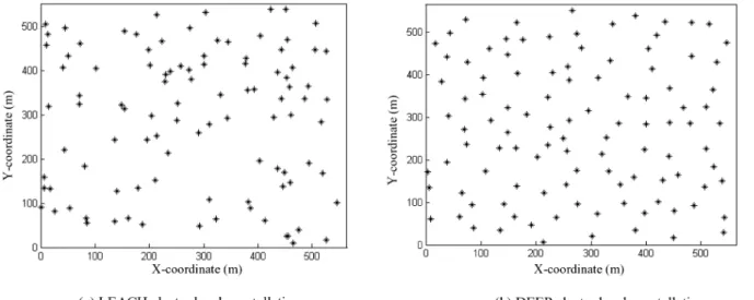
Figure 11 demonstrates the cluster head distri-bution achieved using protocols LEACH and DEEP. Because of the random selection of
clus-Fig. 10. Energy(µJ)consumed by each cluster head to
receive one bit of information from all of the sensor nodes in the cluster.
ter heads in LEACH, some of the cluster heads are too close to each other while others are way too far. This type of cluster head selection causes a lot of burden on some cluster heads and drains their battery very fast.
Figure 10 shows the energy consumption in each cluster head in order to receive one bit of infor-mation from all cluster members using 802.11g technology. Due to the inconsistent distribution of cluster heads (Fig. 11), LEACH puts a lot
of pressure on some of the cluster heads(CH)
while DEEP share out the weight among all of them.
The standard deviation (ESD) among
intra-cluster communication energy consumption as-sociated with cluster heads, for LEACH is 7.7013µJoule/bit, about 8 times larger than
ESD among communication energy consump-tion for DEEP while the average energy con-sumption per cluster head for LEACH is 5.476 µJ/b, about 2.3 times larger than the same
pa-rameter for DEEP. This can prove the fact that DEEP can perform well in terms of balancing the intra-cluster load among cluster heads com-pared to the existing protocol LEACH.
5.2. Re-clustering
In order to prevent over-utilization of some sensor nodes, clustering technique should en-sure that the cluster head responsibility rotates among all sensor nodes. To achieve this, in LEACH5], re-clustering is performed
period-ically, but every round of re-clustering requires several control signal exchanges among self-elected cluster heads and sensor nodes. Re-clustering process in DEEP is based on one small shift in the initial cluster head. When the current period of cluster setting is finished, current initial CH chooses the nearest node that has never been acted as an initial cluster head. This newly chosen initial cluster head starts the clustering process and creates a totally differ-ent cluster head constellation. We simulated the clustering process for 30 rounds. Figure 12 shows the accumulative percentage of the nodes that have become a cluster head at the
Fig. 12.Accumulative percentage of the nodes that have been chosen as cluster head till the end of each round.
end of each re-clustering round. No node be-comes cluster head more than once during the network lifetime. With 3000 sensor nodes, if algorithm generates about 105 cluster heads at each round, after 3000=105
= 28 rounds all
the sensor nodes should have become a cluster head. Figure 12 shows that after 27 rounds of re-clustering, number of generated cluster heads will dramatically drop since most of the eligible nodes have been chosen as cluster head and have lost their energy. For this scenario, DEEP can minimize energy consumption associated with re-clustering overheads by reducing the number of necessary rounds to 27 compared to hundreds or even thousands rounds of re-clustering asso-ciated with LEACH protocol.
5.3. Optimum Percentage of Cluster Heads
In order to find out the optimum cluster head density and compare the performance of the routing protocol on both DEEP and LEACH, we used a 1600-node network nodes were randomly distributed in a field with area of 400400 m.
In this scenario, sensor nodes send the infor-mation directly to their associated cluster head. Each cluster head compresses the data and waits for neighbor cluster heads’ data packet. Then, the cluster head compresses all the received data packets into a packet with fixed length and sends it to the relay neighbor. The relay neighbor address has been saved in the node memory through the propagation of interest signal. In-network data aggregation performed by cluster heads as described above helps to reduce the amount of data dispersed in the network. Our first experiment compares the ESD among energy consumption in cluster heads regard-ing intra-cluster communication for protocols DEEP and LEACH while percentage of clus-ter heads in the network is changing. For the sake of fair comparison, we used the communi-cation energy model described in Section 2 for both protocols. Fig. 13(b)approves the fact hat
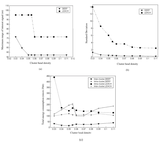
Fig. 13. (a): Maximum range of interest signals;(b): Standard Deviation among intra-cluster energy consumption
associated with cluster heads;(c): Total energy consumption inside clusters and among cluster heads.
both protocols. Figure 13(a)shows the
maxi-mum range of the interest signal (Ri) that
es-tablishes the routes among cluster heads. Since LEACH protocol distributes the cluster heads randomly across the network(Fig. 11(a)),
max-imum range ofRishould be chosen high enough to make sure that all the cluster heads are cov-ered and network does not get partitioned. But as density of cluster heads increases and they get closer to each other,Rican decrease. Since we adjust the maximum range of the output signal by changing the transmission data rate,Ri max-imum value should follow the values provided in Table 2 for 802.11g. Therefore, as Figure 13(a)shows,Richanges from 100 m to 76.5 m,
for LEACH, when cluster head density reaches 0.055 point and from 76.5 m to 57 m, for DEEP, when cluster head density passes 0.03 point. For
a chosen cluster head density, Ri is higher for LEACH compared to DEEP because DEEP pro-tocol distributes the cluster heads consistently. Higher values for Ri, in LEACH, lead to ex-tra route setup overheads and faster network degradation. Figure 13(c)shows the total
inter-cluster communication energy consumption com-pared to total intra-cluster energy consumption. The figure shows the reduction in inter-cluster energy consumption when cluster head density varies from 0.03 to 0.05 for DEEP protocol. We can observe the cause of this effect in Fig. 13(a).
Since maximum range of interest signal(Ri)
WhileRiis remaining constant, inter-cluster en-ergy increases with cluster head density, be-cause larger number of cluster head indicates larger number of communications. We can ob-serve the increase in inter-cluster energy con-sumption when cluster head density varies from 0.06 to 0.11. For lower cluster head percent-age LEACH has significant consumption com-pared to DEEP because cluster heads get further away from each other and both inter-cluster and intra-cluster transmission energies increase. To investigate the optimum density of cluster heads in terms of energy consumption, Figure 14(a)
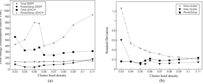
shows the total energy consumption in the net-work to collect one bit of data from every sensor node.
Also Figure 14(a) shows the total overhead
caused in the network by interest flooding and route setup for a network that has been clus-tered using DEEP and LEACH. Also we can observe the significant improvement in the net-work energy consumption using DEEP proto-col. Considering the results from Figure 13(c)
and inverse growth of inter-cluster and intra-cluster energy consumption for DEEP protocol, we can see that the summation of these two energies is almost constant while cluster head density is changing. Therefore, the optimum point for cluster head density can be determined based on the route setup energy and distribution of the load. Total flooding overhead associated with LEACH is considerably higher than DEEP, because of the random distribution of cluster
heads and mandatory high value for maximum transmission range of interest signals. Due to the reduction in the maximum range of interest signals(Figure 13(c)), route setup energy drops
from 805 to 410µJ, for LEACH protocol, when density passes the 0.055 point. At the same time, flooding overhead associated with DEEP drops from 89.6 to 40.1µJ when density reaches the 0.05 point. Route setup energy increases as cluster head density grows more than 0.05 due to the generation of interest signals. From this experiment, the optimum point of operation is around 0.05 for cluster head density.
However, another important parameter to con-sider is distribution of load. Figure 14(b)shows
the standard deviation among energy consump-tion in cluster heads regarding inter-cluster and intra-cluster communication along with the stan-dard deviation among energy consumption in cluster heads regarding route setup communi-cation. From this figure, we can observe that optimum point for route setup and inter-cluster energy consumption is achieved when cluster head density is about 0.05. However, the stan-dard deviation among energy consumption re-garding intra-cluster communications declines as cluster head density increases. Since this re-duction does not lead to a better optimum point, we conclude that 0.05 is the optimum point for cluster head density in terns of both load distri-bution and total energy consumption.
Fig. 14.(a): Total data communication energy consumption in the network along with interest flooding total energy
consumption;(b): Standard Deviation among cluster heads’ intra-cluster, inter-cluster and route setup energy
6. Conclusion
While wireless sensor network introduces chal-lenging energy limitations, clustering protocols can reduce the amount of energy consumption by dividing the network into well-distributed clusters. In this work, we proposed a new energy-efficient clustering protocol(DEEP)that
is based on the idea of controlling the geo-graphical dimensions of clusters and distribu-tion of cluster heads. Because of the balanced load among cluster heads, there is no need for frequent re-clustering, but after current clus-ter heads are out of energy, protocol can rotate the cluster head position among all the sensor nodes. Also, identical distance between a pair of neighboring cluster heads leads to the ease of route setup deployment. After establishing the routes among cluster heads using Inter-Cluster energy conscious Routing (ICR) protocol,
re-sults from our experiments show that DEEP can reduce the energy consumption and distribute the load as nearly as 8 times better than an exist-ing clusterexist-ing protocol LEACH. Optimum point of operation, in terms of cluster head density, is about 0.05.
Another IEEE standard, 802.15.4, has also de-veloped in order to address issues associated with low-rate personal area networks. The new standard, 802.15.4 allows less complex, inex-pensive solutions to be implemented for a wide range of devices. What we are proposing as a new cluster-based routing protocol is a de-sign methodology that can be extended to other standards such as 802.15.4. However, 802.15.4 offers low data rate communication and leads to higher energy consumption during the data transmission phase. At the same time, due to the low complexity associated with 802.15.4, energy consumption during sleep mode or in terms of J/s is much lower than the same
param-eter for 802.11 Standard. Therefore, we suggest deployment of 802.11 for applications that re-quire data transmission phases with high trans-mission frequency and deployment of 802.15.4 for applications that require sensor node to stay in sleep mode most of the time.
References
1] HALGAMUGE, M.N., et. al., Energy Efficient Cluster
Formation in Wireless Sensor Networks,IEEE 10th Int. Conf. Telecom, vol. 2, pp. 1571–1576, March 2003.
2] TILLETT, J., RAO, R., SAHINF., Cluster-Head
Identi-fication in Ad Hoc Sensor Networks Using Particle Swarm Optimization,IEEE Int. Conf. on Personal Wireless Communications, pp. 201–205, Dec. 2002.
3] GUPTA, G., YOUNIS, M., Fault-Tolerant Clustering
of Wireless Sensor Networks,IEEE Wireless Com-mun. and Networking Conf., vol. 3, pp. 1579–1584, March 2003.
4] GUPTA, G., YOUNIS, M., Load-Balanced Clustering
of Wireless Sensor Networks, IEEE Int. Conf. on Comm., vol. 3, pp. 1848–1852, May 2003.
5] GHIASI, S., et. al., Optimal Energy Aware Clustering
in Sensor Networks,MDPI2002.
6] BANDYOPADHYAY, S., COYLE, E. J., An Energy
Ef-ficient Hierarchical Clustering Algorithm for Wire-less Sensor Networks,Twenty-Second Annual Joint Conf. of the IEEE Computer and Commun. Soc., vol. 3, pp. 1713–1723, April 2003.
7] AMIS, D., et. al., Max-Min D-Cluster Formation in
Wireless Ad Hoc Networks, inProceedings of IEEE INFOCOM, March 2000.
8] TAEK, J. K., et. al., Efficient Flooding with
Pas-sive Clustering-an Overhead-Free Selective For-ward Mechanism for Ad Hoc/Sensor Networks,.
Proceedings of the IEEE, vol. 91, Issue 8, pp. 1210–1220, Aug. 2003.
9] RABINER, W., et. al., Energy-Efficient
Communica-tion Protocols for Wireless Microsensor Networks, Hawaii International Conf. on System Sciences
(HICSS ’00), Jan. 2000.
10] CHEN, B., et al., Span: An Energy Efficient
Coordi-nation Algorithm for Topology Maintenance in Ad Hoc Wireless Networks, in theProc. of the 7thACM
Mobile Computing and Comm.(MobiCom 2001),
Rome, Italy, July 2001.
11] WEI, Y. J., et al., An Energy-Efficient MAC
Proto-col for Wireless Sensor Networks,IEEE Proc. on Twenty-First Annual Joint Conference of the IEEE Computer and Communications Societies (
INFO-COM 2002), vol. 3, pp. 1567–1576, June 2002. 12] AKYILDIZ, F., et. al., A Survey on Sensor Networks,
IEEE Communications Magazine, Vol. 40, Issue. 8, Aug 2002.
13] Broadcom white paper,The New Mainstream
Wire-less LAN Standard, softcopy at
http://whitepapers.zdnet.co.uk/ 0,39025945,60072368p-39000522q,00.htm
14] MEHTA, S., et al., A CMOS Dual-Band Tri-Mode
Chipset for IEEE 802.11a/b/g Wireless LAN,2003
15] MIN, R., et. al., Top Five Myths about the Energy
Consumption of Wireless Communication,Mobile Comput. and Commun. Review, vol. 1, Num. 2, 2003.
16] YOUSSEF, M.A., YOUNIS, M.F., ARISHA, K.A., A
Constrained Shortest-Path Energy-Aware Routing Algorithm for Wireless Sensor Network, IEEE Wireless Commun. Networking Conf., vol. 2, pp. 794–799, March 2002.
17] PERKINS, C.E., et. al., Performance Comparison of
Two On-Demand Routing Protocols for Ad Hoc Networks,IEEE Personal Communications, vol. 8, Issue 1, pp. 16–28, Feb. 2001.
18] SHAH, R.C., et. al., Energy Aware Routing for Low
Energy Ad Hoc Sensor Networks, IEEE Wireless Commun. Networking Conf., vol. 1, pp. 350–355, March 2002.
19] S. C. CRIPPS, RF Power Amplifiers for Wireless
Communications, Artech House Publishers, Boston, 1999.
20] L. PETERSON, B. S. DAVIE, Computer Networks,
Morgan Kaufmann, San Francisco, 2003.
21] M. A. YOUSSEF, et al., A Constrained Shortest-Path
Energy-Aware Routing Algorithm for Wireless Sen-sor Networks,IEEE Wireless Commun. Networking Conf., 3(2002), pp. 794–799.
22] E. WOODROW, W. HEINZELMAN, SPIN-IT: a data
centric routing protocol for image retrieval in wire-less networks, International Conference on Image Processing, 6(2002), pp. 913–916.
23] C. INTANAGONWIWAT, et. al, Directed diffusion for
wireless sensor networking, IEEE/ACM Transac-tions on Networking, 2(2003), 2–16.
Received:November, 2004
Accepted:January, 2005
Contact address:
Marzieh Veyseh San Jos´e State University One Washington Square San Jos´e, California USA Phone: 95192-0080 e-mail:[email protected]
Belle Wei San Jos´e State University United States
Nader F. Mir San Jos´e State University United States e-mail:[email protected]
MARZIEHVEYSEHreceived her B.Sc. degree in electrical engineering from Tehran University, Iran in 2002. She received her MSc. degree in electrical engineering in 2004 from San Jos´e State University in Califor-nia. She was a research assistant in San Jos´e State University, working on the design and development of energy efficient communication pro-tocols for wireless sensor network. Since January 2005 she has been working as a network engineer in Doradus Technologies, San Jos´e, Cal-ifornia. She has been conducting research in wireless communication networks with an emphasis on sensor networks, computer networks, switching systems and internet protocols. She has been a member of Tau Beta Pi and Phi Kappa Phi since April 2004 and has contributed in editing numerous technical papers for Journal of Computing and Information Technology and for various IEEE conferences.
BELLEW.Y. WEIreceived an A.B in biophysics in 1977 from the Uni-versity of California- Berkeley, an M.S. in engineering from Harvard University in 1980, and a Ph.D. in electrical engineering from UC-Berkeley in 1987. She is currently the dean of the College of Engineer-ing at San Jos´e State University. Her technical interest areas include sensor network protocols, networking routers/switches, VLSI
archi-tectures and algorithms for video compression/decompression, built-in
self tests, and computer arithmetics. Prior to her appointment as dean, Dr. Wei served as professor and chair of the Department of Electrical Engineering at San Jos´e State. She was a visiting associate professor at Stanford University(1993-94)where she conducted research in
de-veloping low-power wireless processors for video decompression and graphics display, and developed error-resilient video decompression al-gorithms. Dr. Wei has been an active member of the IEEE since 1987 and has served as a program committee member for international con-ferences. In December 2004, she received a Special Congressional Recognition for Outstanding and Invaluable Service to the Community.
NADERF. MIRreceived his B.Sc. degree(with honors)in electrical
engineering in 1985 and his M.Sc. and Ph.D. degrees, both in elec-trical engineering, from Washington University in St. Louis, MO, in 1990 and 1994 respectively. He is currently an Associate Professor at the Electrical Engineering Department of San Jos´e State University, California. Prior to this position, he was an Assistant Professor of electrical and computer engineering at the University of Kentucky in Lexington. From December 1994 to July 1996, he was a research scien-tist at the Advanced Telecommunications Institute, Stevens Institute of Technology in New Jersey, working on the design of advanced telecom-munication networks. From 1990 to 1994 he was with the Computer and Communications Research Center(CCRC)at Washington