Model 10A
Electric Switch Lock
TABLE OF CONTENTS
SECTION 1 – INTRODUCTION
SCOPE OF MANUAL
... 1-1
OPERATION – NORMAL RELEASE
... 1-1
Preliminary Unlock Position ... 1-1
Unlock Position ... 1-2
Switch Reverse ... 1-3
Relock Position ... 1-3
Normal Position ... 1-3
OPERATION – EMERGENCY RELEASE
... 1-3
Preliminary Unlock Position ... 1-3
Emergency Release Cover Raised ... 1-4
Emergency Release Lever Turned ... 1-4
Hand-Throw Lever Reverse ... 1-4
Emergency Release Cover Closed ... 1-4
Resetting Emergency Release ... 1-4
Inserting Latch Padlock ... 1-5
SECTION 2 – INSTALLATION
GENERAL
... 2-1
Model 50/51 Switch Stand ... 2-1
Meridian (Racor) Switch Stands 36D & 36H ... 2-3
SECTION 3– WIRING
GENERAL
... 3-1
SECTION 4-MAINTENANCE
LUBRICATION
... 4-1
ADJUSTMENTS
... 4-2
SECTION 5– PERIODIC INSPECTION
WEAR CHECK ...5-1
SECTION 6– REPLACEMENT PARTS
GENERAL ...6-1
PARTS LIST ...6-4
Figure No. Description Page #
1-1 Operating Parts of Model 10A Switch Lock Shown Locked in Normal Position 1-2 2-1 Model 10A Lock on Model 50/51 Switch Stand 2-2 2-2 Model 10A Lock on Meridian (Racor) 36D and 36H Switch Stand 2-3 3-1 Typical Connection Diagrams Showing Binding Post Designations, Internal Wiring,
and Contact Arrangements 3-1
3-2 Typical Application Circuits Showing the Model 10A Switch Lock applied to Absolute
Permissive Block Signaling 3-2
4-1 Latch Stand Lubrication Fittings 4-1
5-1 Model 10A Switch Stand Lock 5-1
6-1 Model 10A Switch Lock Mechanical Assembly 6-1
6-2 Model 10A Switch Lock Part References 6-2
6-3 Model 10A Switch Lock Component Parts References 6-3
6-4 Model 10A Switch Lock Relay Assembly 6-7
6-5 Model 10A Switch Lock Relay Components 6-8
SECTION 1
INTRODUCTION
SCOPE OF MANUAL
This manual contains information to enable a field maintainer or shop repairman to understand the operation of the Model 10A Electric Switch Lock, know how to test its operation and be able to order spare or replacement parts.
The Alstom Model 10A Electric Switch Lock is used to securely lock the hand-throw lever of a hand operated switch machine or a ground-throw switch stand in the normal position, and it may be applied to either a right-hand or left-hand layout. The lock also interlocks a manually operated switch with signal circuits, so the switch cannot be operated unless traffic conditions permit, or unless the normally sealed emergency release is operated. This pamphlet describes the normal and emergency release operations, internal wiring, maintenance and installation of the lock with a variety of switch stands
.
OPERATION - NORMAL RELEASE
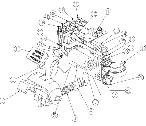
Starting with the switch locked in its normal position, the following describes, step by step, the operation of the lock mechanism. The references to the various parts are shown in Figure 1-1.
Preliminary Unlock Position
When the padlock is removed from hole 2 in latch 1, the latch is forced upward by pedal 3, which is operated by spring 4 acting against the shoulder of plunger 6.
Plunger 6, moving forward under spring pressure, rotates cam 7, driving the sloped cam face under the roller on the underside of operating arm 13. Cam 7 continues to rotate in this same direction until the collar on plunger 6 strikes the end of its housing. The roller under arm 13, meanwhile, has moved up the sloped cam face, carrying arm 13 with it, and thereby tilting plate 9 and the fingers of the mechanically operated contacts, 2B, 3F, and
WARNING!
When operating switch machines, keep head and body clear of the path of the hand-throw lever. Stored mechanical energy, caused by improper adjustment, shifts in rails, and other switch components, or obstructions, can be transferred to the hand-throw lever during hand operation, causing it to move rapidly and forcefully.
Difficulty in hand-operating the switch could indicate a potential hazard. If any of these conditions are observed, check that the switch is adjusted properly as described in this pub-lication.
4B, which are attached to it. Thus, the normally closed (back) contacts are opened and the normally open (front) contacts are closed.
Unlock Position
With the padlock removed, the lock is still effective because the armature arm 15 is resting in a locking notch formed by a step on the cam face of operating cam 7 and a cast projection on the lock case. When conditions are such that the control circuit is energized, armature 8 is attracted to the pole faces of coil 12 and raises its attached armature arm 15 out of the locking notch. With operating cam 7 unlocked, it is free to rotate further as pressure is applied to pedal 3. With this additional level of the pedal, latch 1 withdraws completely from the hand-throw lever slot, thus permitting the raising of the hand-throw lever .
When armature 8 is attracted to the pole faces, it moves the fingers of the electrically operated contacts 1F and 5B which are attached to it. Thus, the normally closed (back) contacts are opened and the normally open (front contacts are closed.
Figure 1-1. Operating Parts of Model 10A Switch Lock Shown Locked in Normal Position
Section 1 Introduction
Switch Reverse
Lighting of the green LED 11 indicates that the hand-throw lever may be lifted and moved to its reverse posi-tion. Stepping on pedal 3 now withdraws latch 1 and permits the hand-throw lever to be thrown to reverse po-sition. Before the trainman can lock up the mechanism, it is necessary to restore the switch to its normal posi-tion. Otherwise, the latch rod will be in the way of projection 5 on the latch, and the pedal cannot move to its normally locked position and latch 1 cannot be down.
Relock Position
As the hand-throw lever is returned to its normal position, the latch rod slides clear of projection 5 on latch 1. This allows latch 1 to return to its preliminary unlock position.
Normal Position
Depressing latch 1 moves operating cam 7 back to its normal locked position. Operating bar 13 is forced down by spring pressure as cam 7 moves back. Armature arm 15 is forced down onto cam 7 by projection spur 14 on the operating arm and spring pressure. Thus, all contacts are forcibly returned to their normal positions. Lock coils 12 are de-energized by the forced opening of contact 3F, indication LEDs are de-energized by the forced opening of contact 1F.
Reinsert the padlock into hole 2.
OPERATION– EMERGENCY RELEASE
When the normal control circuit does not respond and the switch must be unlocked and operated for emergency reasons, the emergency release (an optional feature) must be used.
Starting with the switch locked in its normal position, the operation of the lock by the trainman and the resulting action of the mechanism is as follows:
Preliminary Unlock Position
When the padlock is removed from hole 2 in latch 1, the latch is forced upward by pedal 3, which is operated by spring 4 acting against the shoulder of plunger 6.
Plunger 6 moving forward under spring pressure, rotates operating cam 7, driving the sloped cam face under the roller on the underside of operating arm 13. Cam 7 continues to rotate in this same direction until the collar on plunger 6 strikes the end of its housing. The roller under arm 13, meanwhile, has moved up the sloped cam face, carrying arm 13 with it, and thereby tilting plate 9 and the fingers of the mechanically operated contacts, 2B, 3F, and 4B which are attached to it. Thus, the normally closed (back) contacts are opened and the normally open (front) contacts are closed.
Section 1 Introduction
Emergency Release Cover Raised
Note that cover 18 cannot be raised until the lock is in the preliminary unlock position; cam 7 must be moved forward to a point where rod 19 can enter slot 17 to allow cover 18 to be raised. Cover 18 will remain open unsupported.
Emergency Release Lever Turned
Removing seal 21 and turning emergency release lever 20 counterclockwise, until its movement is stopped by a flange, attached latch 16 moves under operating and armature arms 13 and 15, lifting armature arm 15 and positioning the contacts just as though the lock coils had been energized by the control circuit.
Hand-Throw Lever Reverse
Depressing pedal 3 moves latch 1 back out of the way. Latch 1 is free to move because armature arm 15 is raised out of the step in cam 7, thus leaving the cam free to rotate as pedal 3 moves plunger 6 forward. As the lever is lifted, the latch rod moves in and holds latch 1 in the unlocked position, preventing the mechanism from being locked up until the switch has been restored to the normal position.
Emergency Release Cover Closed
As emergency release cover 18 is closed, the projecting cam surface on the inside of the cover engages emergency release lever 20, turning it so that attached latch 16 moves out from armature arm 15. Spring 10 forces armature arm 15 down into its normal locked position on operating cam 7. As armature arm 15 assumes its locked position, it causes the electrically operated contacts to assume their normal position.
Latch 16 is furnished with a barb on its upper edge. This barb catches on the side of arm 13, hiding arm 13 and its associated contacts from returning to their normal positions. To restore the lock requires the attention of an authorized person as explained next.
Resetting Emergency Release
This must be done by a person who has a key to the housing padlock. See WARNING! on page 1-1 Remove the switch padlock and the mechanism case padlock.
Open mechanism case. Lift operating arm 13 to allow latch 16 to drop fully back to its normal position. When arm 13 is released, it restores to the preliminary unlock position. Now, when the latch is pressed down prior to inserting the padlock, the mechanically operated contacts as well as the electrically operated contacts will be in their normal position.
Open emergency release cover 18 and reseal emergency release lever 20. Close cover 18 and the mechanism case cover, and reinsert the padlocks.
Section 1 Introduction
Inserting Latch Padlock
Depress latch 1 to raise pedal 3. Cam 7 will move fully back to its normal position. Insert the padlock in hole 2, thus maintaining the normal locked position.
Section 1 Introduction
GENERAL
When installing Model 10A locks, refer to the switch layout drawing or railroad standard installations. Instructions for applying the lock to various types of switch stands are given on the following pages.
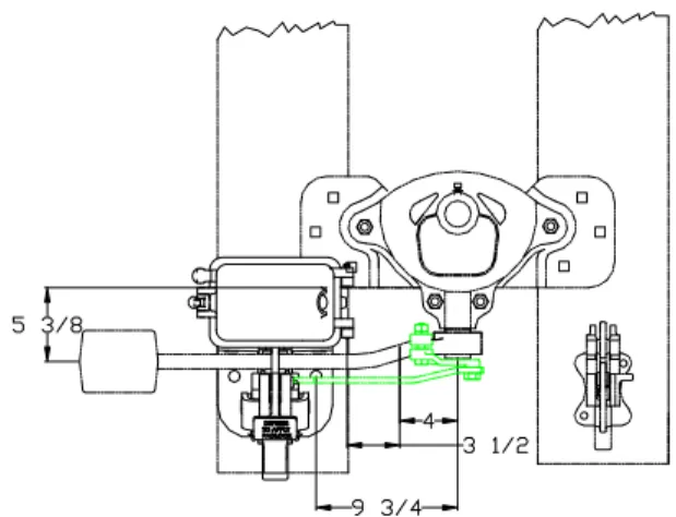
Locks are shipped with all parts to fit the switch stands described in this section. The lever guide is fitted with two 1/8-inch thick shims for 3/4-inch thick hand-throw levers. One of these shims may be removed when a 7/8-inch hand-throw lever is used and both shims may be removed when a 1-inch thick lever is used. There should be no more than 1/8-inch total clearance between the sides of the hand-throw lever and the sides of the pocket in Model 10A lock. See WARNING! on page 1-1.
Model 50/51 Switch Stand
1. Bolt clamp 2 to switch lever, Figures 2-1A and 2-1D.
2. Using a 3/8-inch drill, drill through clamp and lever and install rivet 4, Figure 2-1D. 3. No tie dapping, Figure 2-1B.
4. Install cable entrance adapters and ventilators before bolting lock in place. Secure lock on tie with rods, grip washer, nuts, and lock washers as shown.
5. To assemble latch rod 3, place switch lever in locked-up position, Figure 2-1A. Press pedal down and insert latch rod through rectangular hole in lock stand. Insert stud 6 through pivot hole in latch rod and temporarily secure it to clamp. Depress latch as far as it will go and hold it in this position. Scribe across face of latch rod next to pedal casting, Figure 2-1C. Remove stud and latch rod. Cut off latch rod 1/32-inch short of scribe mark.
6. For adjustable latch rod follow previous procedure, except adjust latch rod in 1/8” increments instead of cutting.
7. In final assembly, tighten stud 6 with a wrench to secure latch rod to clamp. Drill through clamp and stud with a 1/8” drill. Insert pin 5, Figure 2-1D.
SECTION 2
INSTALLATION
Figure 2-1. Model 10A Lock on Model 51/50 Switch Stand
A - LAYOUT OF LOCK ON SWITCH STAND
B - INSTALLATION OF LOCK ON SWITCH STAND
C -LATCH ROD ARRANGEMENT
D - PIN THROUGH
CLAMP & LEVER
SCRIBE HERE
3 4 2 4 2
6 3/8”
5
Section 2 Installation
Meridian (Racor) Switch Stands 36D & 36H
1. Bolt clamp 2 to switch lever, Figure 2-2C.
2. Using a 3/8-inch drill, drill through clamp and lever and install rivet 4, Figure 2-2C. 3. Install cable entrance adapters and ventilators before bolting lock in place. Secure lock on supporting plate 12 and tie with threaded rod, bolt, nuts, and washers to fit switch stand lever, Figure 2-2A.
4. To assemble latch rod 3, place switch lever in locked-up position, Figure 2-2B. Press pedal down and insert latch rod through rectangular hole in lock stand. Insert stud bolt 14 through pivot hole in latch rod and temporarily secure it to clamp. Depress latch as far as it will go and hold it in this position. Scribe across face of latch rod next to pedal casting, Figure 2-2B. Remove stud and latch rod. Cut off latch rod 1/32-inch short of scribe mark.
5. In final assembly, tighten stud 14 with a wrench to secure latch rod to clamp. Drill through clamp and stud with a 1/8” drill. Insert pin 5.
Figure 2-2. Model 10A Lock on Meridian (Racor) 36D and 36H Switch Stand
14 SCRIBE HERE 2 4 3
3/8” DRILL THROUGH LEVER & CLAMP 4
A - INSTALLATION OF LOCK ON SWITCH STAND
B - LATCH ROD ARRANGEMENT C - PIN THROUGH CLAMP & LEVER
5
Section 2 Installation
GENERAL
To wire the Model 10A lock, Remove the relay assembly from the case by taking out the four screws which hold it in place. Run the wires into the case through the cable entrance adapters, cutting them long enough to leave slack after connecting to the terminals.
Remove the wire guides located on each side of the mechanism; separate the wires so that half of them come up each side of the relay. Strip the insulation and apply connectors. Replace the guides after the wires are con-nected to the terminals. Replace the relay assembly in the case, making sure that the armature arm is free to operate vertically without rubbing on the stop in the case.
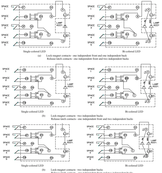
Single-colored LED Bi-colored LED
(a) Lock-magnet contacts– one independent front and one independent back Release-latch contacts– one independent front and two independent backs
Single-colored LED Bi-colored LED
(b) Lock-magnet contacts– two independent backs
Release-latch contacts– one independent front and two independent backs
Single-colored LED
(b) Lock-magnet contacts– two independent backs
Release-latch contacts– one independent front and two independent backs Bi-colored LED
SECTION 3
WIRING
Figure 3-1. Typical Connection Diagrams Showing Binding Designations, Internal Wiring, and Contact Arrangements.
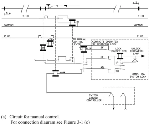
Figure 3-2. Typical Application Circuits Showing the Model 10A Switch Lock Applied to Absolute Permissive Block Signaling.
Section 3 Wiring
(a) Circuit for manual control.
For connection diagram see Figure 3-1 (c)
(b) Circuit for automatic control.
LUBRICATION
Figure 4-1 shows the latch stand lubrication fittings A, B, C, and D. Lubricate latch stand with an all temperature, lithium-based grease not more than once every three months.
Referring to Figure 1-1, lubricate pin 22 occasionally with a light oil, such as Mobil Aero. Other bearing points are permanently lubricated and require no attention.
Operate the lock after lubricating it to be sure that the lubrication is keeping the lock free to operate correctly.
Figure 4-1. Latch Stand Lubrication Fittings
A B
D
C
SECTION 4
MAINTENANCE
ADJUSTMENTS
The following information will be useful in checking the contact openings and pressures (adjust pressure by bending the stops; adjust opening by bending the contact fingers):
A. Padlock in place
1. Electrically operated contacts: a. Front-open .050” minimum
b. Back-closed with pressure of 8 to 10 oz. This high pressure is obtain by mechanically driven back stop. See Figure 1-1.
2. Mechanically operated contacts: a. Front-open .050” minimum
b. Back-closed with pressure of 8 to 10 oz. B. Padlock removed -lock de-energized
1. Electrically operated contacts: a. Front-open .050” minimum
b. Back-closed with pressure of 3 oz min. 2. Mechanically operated contacts:
a. Front-closed with pressure of 6 to 8 oz. b. Back-open .050” minimum
C. Padlock removed-lock energized 1. Electrically operated contacts:
a. Front -closed with pressure of 3 oz min. b. Back-open .050” minimum
2. Mechanically operated contacts:
a. Front-closed with pressure of 6 to 8 oz. b. Back-open .050” minimum
After the contact openings and pressures have been adjusted to the above specifications, the operating values, i.e., the pickup-up and drop-away currents, for operations on 8-10 volts (100 ohms) should be checked that they meet the specifications listed below. Spring, item #10, Figure 1-1, can be bent to adjust the downward pressure on the armature arm to achieve these specifications.
Lock Resistance
Maximum Pick-Up Current Minimum Pick-Up Current
Minimum Drop-Away Current
100 ohms ±10% .055 ampere .035 ampere .007 ampere
Section 4 Maintenance
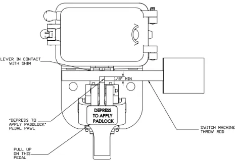
WEAR CHECK
At least yearly the switch lock should be checked for wear, using the following procedure:
There should be no more than 1/8-inch total clearance between the sides of the switch stand operating lever and the sides of the switch lock. Add shims, if necessary, to reduce the clearance to an 1/8-inch.
1. Place the switch lock in the locked position with a padlock in place. 2. Pull up on the “Depress to Apply Padlock” pedal.
3. The “Depress to Apply” pedal pawl should prevent the switch machine throw rod from being removed from the machine lock by a minimum of 1/8-inch (See Figure 5-1), with the switch stand operating lever driven toward the shimmed side of its opening.
4. If the pedal pawl restraint is less than 1/8-inch, replace the worn mechanical parts of the switch lock. (As a minimum, this would include both foot pedals, plus the associated shafts and bushings.)
If mechanical parts are replaced, it is recommended that the pedal pawl interference be at least 3/8-inch. When the 3/8-inch decreases to 1/8-inch, replace the worn parts again.
SECTION 5
PERIODIC INSPECTION
GENERAL
This section identifies and lists the component parts that may be ordered to replace the same in the field or at the shop level. Parts are identified by Alstom part numbers.
PARTS LIST
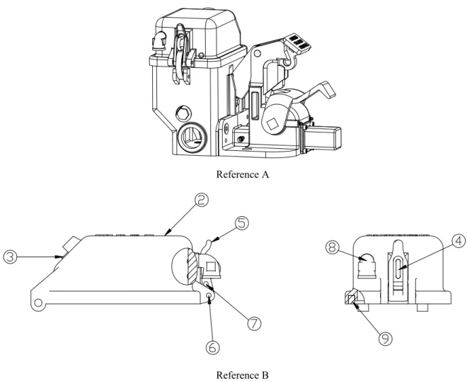
Switch lock illustrations are followed by a parts list giving part descriptions, and numbers of replaceable parts. Index numbers are given in each parts list to precisely locate referenced parts in the illustration. This section of the manual covers currently manufactured parts that are available as spares.
Reference A
Reference B
Figure 6-1. Model 10A Switch Lock Mechanical Assembly
SECTION 6
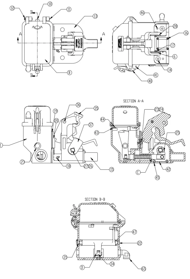
Figure 6-2. Model 10A Switch Lock Part References
Section 6 Replacement Parts
Figure 6-3. Model 10A Switch Lock Component Parts References
Reference C
Reference E Reference D
Section 6 Replacement Parts
Ref. Description Alstom Part Number
A ELECTRIC LOCK, MECHANICAL ASSEMBLY 854600-000-00
1 BASE, 854 ELECTRIC LOCK 854133
B COVER ASSEMBLY, LOCK 854134-001-01
2 COVER, LOCK 854134
3 LENS, SIGHT 854145
4 STAPLE 854148
5 HASP, MACHINED 854140
6 PIN, HASP 854151
7 PIN, HASP 854171
8 VENTILATOR, COMPLETE 857109-001X
9 GASKET, COVER 854134-030
10 HINGE PIN 854135-001
11 HINGE PIN 854135-002
12 COTTER PIN, 0.125 X 0.750 Z/Y 990506-075-02
13 BASE, FOOT LEVER 854102
14 SCREW, 0.500 X 0.750 FHSCS SS 073957-075-30
15 COVER, REAR 854107
16 SCREW, 1/4 BTN HEAD SKT CAP 073752-050-30
17 FITTING, 0.187 STR DRIVE 990900-004
18 FITTING, 0.125 65 DEG PTF 990900-007
19 SHIM, GUIDE PLATE 854120
20 PLATE, GUIDE 854119
21 TRUNNION,CAM 854110
22 TRUNNION,CAM 854111
23 WASHER, TRUNNION 854112
24 WASHER, 0.312 NARROW FLAT Z/Y 990600-031-002 24 SCREW, 0.312-18 X 0.750 HEX Z/Y 990723-075-22
25 CAM BLOCK, FOOT LEVER 854116
26 SET SCREW, CAM 854117
27 CAMSHAFT, FOOTLEVER 854100
28 BUSHING, CAM PEDAL 854113
C ROD ASSY, CONNECTING 854105X
29 ROD, CONNECTING 854105
Section 6 Replacement Parts
Model 10A Electric Switch Lock
Replacement Parts
Ref. Description Alstom Part Number
30 ROD WASHER, CONNECTING 854105-001
31 SLEEVE, CONNECTING 854106
32 SLEEVE WASHER, CONNECTING 854106-001
33 SPRING, CONNECTING ROD 854153
34 PIN, LINK 854104
35 LATCH, LOCK LEVER 854101
36 PIN, LOCK LATCH 854114
37 CAM, FOOT LEVER 854103
D CAM ASSEMBLY, OPERATING 854136X
38 CAM,OPERATING 854136
39 BUSHING, OPERATING CAM 854150
40 STRAP G30804-018
41 PIN, HASP 854161
42 PLATE, BOTTOM COVER 854108
43 WASHER, .25 INT TOOTH S.S. LOCK 078113-025-40
44 SCREW, 0.250 X 0.750 RH SS 072589-075-30
45 SCREW, 10-32 X .5 FH PHIL S.S. 072682-050-30
46 PIN, #6 X 1.000 TAPER 069146-100-00
47 SHIM PACK
SHIM, OPERATING CAM 854160-005-40
SHIM, OPERATING CAM 854160-010-40
SHIM, OPERATING CAM 854160-020-40
SHIM, OPERATING CAM 854160-031-40
SHIM, OPERATING CAM 854160-040-40
E RELEASE ASSY, EMERGENCY 854128-001-01
48 HOUSING, EMERGENCY RELEASE 854129
49 COVER, EMERGENCY RELEASE 854128
50 CAM, RELEASE LOCKOUT 854125
51 PIN, EMERGENCY RELEASE 854126
52 PIN, EMERGENCY RELEASE SAFETY 854124
53 PIN, 1/8 X 3/4 S.S. SPRING 990563-075-70
54 SHAFT, RELEASE PAWL 854137
55 PAWL, RELEASE 854138
Section 6 Replacement Parts
Model 10A Electric Switch Lock
Replacement Parts (cont.)
Ref. Description Alstom Part Number
56 HANDLE, EMERGENCY RELEASE 854121
57 WASHER, #8 FLAT Z/Y 033072-008-02
58 PIN, RELEASE SAFETY 854123
59 PIN, RELEASE STOP 854131
60 GASKET, EMERGENCY RELEASE 854130G
61 SCREW, #10-32 X 0.500 FHSCS SS 073871-050-30
62 PIN, RELEASE LOCKOUT 854122
63 SPRING, EMERGENCY RELEASE 854127
64 SCREW, #8-32 X 0.375 SLT RD HD 028863-037-01
65 VENTILATOR, COMPLETE 857109-001X
Section 6 Replacement Parts
Model 10A Electric Switch Lock
Replacement Parts (cont.)
Figure 6-4. Model 10A Switch Lock Relay Assembly
Section 6 Replacement Parts
Figure 6-5. Model 10A Switch Lock Relay Components
Reference B
Reference C Reference D
Section 6 Replacement Parts
Ref. Description Alstom Part Number
A Relay Assembly Complete, has the following contact combination with bi-colored LED:
1F and 1B electrically operated 2F and 1B mechanically operated
854077-401-02 A1 Same as Ref. A, except has the following contact combination with
single-colored LED:
1F and 1B electrically operated 2F and 1B mechanically operated
854077-401-01 A2 Same as Ref. A, except has the following contact combination with
bi-colored LED:
2B electrically operated
1F and 2B mechanically operated
854077-400-02 A3 Same as Ref. A, except has the following contact combination with
single-colored LED:
2B electrically operated
1F and 2B mechanically operated
854077-400-01
1 COIL, RELAY 854077-351
2 WASHER, WAVE SPRING 854077-352
3 POST, #14 X 2.250 AAR BINDING 990102-250-55
4 YOKE 854077-355
5 SCREW, .25-20 X 1.25 HX HD S.S. 990722-125-40
6 NUT, .25-20 HVY HX S.S. 990331-025-40
7 WASHER, .25 INT TOOTH S.S. LOCK 078113-025-40
8 SPRING, OPERATING BAR 854077-359
9 COTTER PIN, 0.062 X 0.375 Z/Y 990502-037-02
10 PIN, HINGE 854077-361
11 HINGE BLOCK 854077-364
12 PIN, 1/8 X 3/4 S.S. SPRING 990563-075-70
13 CORE 854077-367
14 NUT, CORE RETAINING 854077-368
15 WASHER, #14 AAR 990101-008-55
16 FRAME, RELAY 854077-371
17 SCREW, 10-32 X .875 PHILLIPS S.S. 072535-087-30 18 WASHER, #10 INT TOOTH LOCK S.S. 078109-010-40 19 SCREW, #10-32 X 0.500 PAN HD PHIL. 072515-050-30
Section 6 Replacement Parts
Model 10A Electric Switch Lock
Relay Assembly Replacement Parts
Model 10A Electric Switch Lock
Relay Assembly Parts (cont.)
Ref. Description Alstom Part
Number B BOARD ASSY, TERMINAL, with front contact in space 3 and back
contacts in spaces 2 and 4, for Ref A1 & A2 854077-050-02 B1 As previous, except with front contacts in spaces 2 & 3 and back
con-tact in space 4, for Ref A2 & A3
854077-050-01
20 BOARD, 854 LOCK TERMINAL 854077-001
21 CONTACT, SHORT BACK 854077-002-01
22 CONTACT ASSY, BACK 854077-003-01
23 CONTACT ASSY, FRONT 854077-004-01
23A CONTACT, FRONT 854077-025-01
24 SCREW, #6-32 X .375 PHILLIPS S.S. 072385-037-30
25 SUPPORT, LEAD 854077-009
26 WASHER, #6 INT TOOTH S.S. LOCK 071105-006-60
27 LEAD ASSY, 2-4 854077-011-01
28 LEAD ASSY, #3 854077-012-01
29 LEAD ASSY, 1-5 854077-013-01
30 POST, #14 X 1.875 AAR BINDING 990102-187-55
C ASSEMBLY, ARMATURE 854077-100-01
31 ARMATURE 854077-051
32 HINGE BRACKET 854077-052
33 EXTENSION ARM 854077-053
34 DOG, LOCK 854077-054
35 PLATE, WASHER 854077-055
36 RIVET, ARMATURE PLATE 854077-056
37 RIVET, .125 X .75 FH COPPER 854077-057
38 SCREW, 10-32 X .5 FH PHIL S.S. 072682-050-30
D OPERATING BAR ASSEMBLY 854077-150-01
39 BAR, OPERATING 854077-101
40 SPRING, OPERATING BAR 854077-102
41 ROLLER, OPERATING BAR 854077-104
42 HEEL CONTACT ASSY, OPER BAR 854077-200-02
42A HEEL CONTACT ASSY, OPER BAR for B1 854077-200-01
43 NUT, #6-32 S.S. HEX 070705-006-30
44 CONTACT ASSEMBLY, ARMATURE 854077-250-02
Section 6 Replacement Parts
Ref. Description Alstom Part Number
44A CONTACT ASSY, ARMATURE 854077-250-01
45 KIT, TERMINAL HARDWARE (not shown) 854077-350-01
46 BOARD ASSY, BI-COLOR LED 854077-300-02
46A BOARD ASSY, LED (single-colored LED) (not shown) 854077-300-01
47 WASHER, #6 FLAT S.S. 071005-006-30
48 TERMINAL, RING TONGUE 34105
Section 6 Replacement Parts