©Science and Education Publishing DOI:10.12691/materials-6-1-1
Fracture Toughness of Copper/Glass-Reinforced
Epoxy Laminate Composites
Mohamed K. Hassan1,3, Mohammed Y. Abdellah2,3,*, Ahmed F. Mohamed3,4, Tareq S. ElAbiadi1, S. Azam3, W.W. Marzouk1
1Production Engineering and Design Department, Faculty of Engineering, Minia University, 61111 Minia, Egypt 2Mechanical Engineering Department, Faculty of Engineering, South Valley University, Qena, 83523
3Mechanical Engineering Department, Collage of Engineering and Islamic Architecture, Umm Al-Qura University Makkah, KSA 4Mechanical Engineering Department, Faculty of Engineering, Sohage University, Egypt
*Corresponding author: mohammed_yahya42@yahoo.com
Abstract In last decades, hybrid composite materials play a competitive role in many industrial applications such
as electrical and electronic industries. Copper/Glass-Reinforced Epoxy Laminate is a hybrid composite that is used in almost all electronic devices. Since these elements undergo different stress amplitudes under different working conditions, therefore the fracture toughness of such material is important to understand the failures occurred under different operating conditions. The present work aims to investigate the fracture behavior of these composites by experimentally measuring and predicting their fracture toughness and by numerically building the model. At the first stage, a center-notched tensile specimen is used to measure fracture toughness in mode I at room temperature; an average fracture toughness of 34.92 𝑀𝑃𝑎√𝑚 with SDV 0.5556 𝑀𝑃𝑎√𝑚 is found. At the second stage, X-FEM is implemented to a simple numerical model to predict the fracture toughness of such a material and to measure stresses induced through the specimen during applied stress. The variation of both, predicted fracture toughness and cohesive stress at the crack face with crack opening displacement, shows thatthe finite element results are in good agreement with the experimental results.Keywords
: fracture toughness, X-FEM, MEMS, laminate, center edge notchCite This Article: Mohamed K. Hassan, Mohammed Y. Abdellah, Ahmed F. Mohamed, Tareq S. ElAbiadi,
S. Azam, and W.W. Marzouk, “Fracture Toughness of Copper/Glass-Reinforced Epoxy Laminate Composites.” American Journal of Materials Engineering and Technology, vol. 6, no. 1 (2018): 1-7. doi: 10.12691/materials-6-1-1.1. Introduction
In recent years, hybrid composite materials have widely used in electronic industry in the form of micro-electrical mechanical systems (MEMS) [1]. Mechanical and thermal properties affect strongly on the performance of (MEMS) from the reliably perspective [2]. Although, there are many studies devoted to model, design, selection and fabrication processes of composite materials used as (MEMS) still studies concerning with the characteristics of their reliably, durability, fracture behavior during operating conditions are not fully reported [3].
The fatigue behaviors of thin copper film bonded to the steel substrate using two types of bonding techniques have been envisaged by Hassan et al [1]; one is an epoxy resin and the other is the diffusion bonding. Their results showed that the fatigue performance affected by the diffusion technique.
The fracture Jc for polysilicon specimen has been
studied by R. Ballarini et al [3]. These specimens are machined in a similar and identical way as (MEMS). The results indicated that the released energy of these polysilicon specimen is four times greater than those of single crystal. On the other hand, the fracture toughness of
thin films used in (MEMS) devices has been investigated [4]. The fracture toughness behaviors of the ultra-nanocrystalline diamond were measured. This study established that the initiation fracture for bland crack is larger than that of a sharp crack tip; it gave a correction factor value for the material using the model of Drory et al. [5].
The Finite Element Analysis (FEA) for experimental results is used [6] to measure the fracture toughness of polysilicon used in (MEMS) devices. An especial sharpened mechanism has been employed to ensure accurate crack initiation and propagation prediction. Unlike the work of Sharpe, et al [7] and Tsuchiya et al. [8], the fracture toughness of MEMS was measured infinite radius notch by fracturing their specimen using a piezoelectric load cell. A simple numerical model, using finite element, was extracted to predict the parameters of the essential work of fracture (EWF) [9] in the thin aluminum strip. The experimental results were in good agreement with the proposed model, but the specimen was on the scale of a millimeter. Other works [10,11,12] reported on the size effect of copper thin film bonded to a steel plate substrate which is considered as quasi-brittle material.
experimental test investigated the size effect of quasi-brittle material [14]. This combination established good prediction for size effect and gave reasons for the size effects on the nominal strength of this material. Consequently, the study reached to some solution for size effect on the quasi-brittle material. Generally, many works measured fracture toughness of composite laminates materials which are widely used in many industrial applications [15,16,17,18,19].
This work aims to measure the fracture toughness of composite materials which consist of a thin copper layer bonded to a substrate of the glass-reinforced epoxy laminate. These composites are widely used as a component in (MEMS) devices. Since, the mechanical behavior is a dominated parameter when using these composite as (MEMS) devices, a better knowledge of fracture behavior would certainly lead to the improvement of the performance and reliability of these devices.
2. Material and Experimental Procedure
Figure 1 shows the composite structure used in this study. The structure consists of glass fiber reinforced epoxy laminate of 1.5 mm thick and a thin copper film bonded to the base of the fiberglass laminate by epoxy
resin. A thin copper film nearly 35 microns and 24 layers of woven glass fiber are used to form this composite structure. Table 1, Table 2 and Table 3 list the chemical composition, electrical and mechanical properties of the copper and epoxy, respectively. According to ASTM D3039 tests standards, the tensile test is performed on all glass fiber reinforced epoxy laminates [20]. Figure 2 illustrates the tensile specimen dimensions. All tests are carried out by the universal testing machine (Model WDW-100) of normal load capacity 200 kN and at a controlled test speed of 2 mm/min. In order to determine the unnotched tensile strength of the composite structure, the unnotched test specimens are used.
In order to measure the surface release energy of hybrid composite, Soutis et al. [21] established a model and introduced a center crack plate tension specimen. Therefore, five center crack plate specimens are prepared with dimensions as shown in Figure 3. Center crack length (2a) =15 mm is cut, using Proto Mat S103 PCB milling machine from LPKF, with 1mm diameter end mill cutter. All specimens are loaded in tension until failure while the load and displacement are recorded on a universal testing machine (model WDW-100) of maximum capacity 200 KN. The cross-head speed of the test is selected to be 2 mm/min according to [22]. Each test repeated for the five specimens.
Table 1. Chemical composition of the copper film and base glass fiber [1]
Phase Al Ni Sn Pb Fe Zn Mn
Copper film 0.0005> 0.0005> 0.0005> 0.0005> 0.0005> 0.0005> 0.0005>
Glass fiber E-glass -roving-pl=2200 gm/km
Epoxy Resin-Kemapoxy(150RGL)
Table 2. Mechanical properties [1]
Phase Young modulus, E (GPa) Thermal of linear expansion, 𝜶/𝑲
Copper film 123 1.68 x 10⁻⁵
Glass fiber 24(Length Wise), 21 (Cross Wise) 4.0 x 10⁻⁵
Epoxy 1.2-4.5 ---
Table 3. Electrical properties
Phase Electrical Resistivity, ρ (Ω•m) Dielectric Strength, V/𝒎𝒊𝒍
Copper film 1.68×10⁻⁸ [22] ---
Glass fiber 10 [23] >762 [23]
Epoxy >1x10⁵ [24] 500 [24]
Figure 1. Schematic drawing of MEMS components
Figure 3. Center edge notch specimen [23]
3. Finite Element Model
A numerical method called extended finite element method (X-FEM) recently created by Belytschko and Black [24], is based on Melenk and Babuska [25] who used the concept of partition of finite element unity and enrichment function. X-FEM differs from FEM method by that the mesh does not need to be updated to follow the crack path [26], this means that there is no need to mesh and re-mesh the complex discontinuities surfaces. So, the fracture analysis can be performed when the crack propagates without re-meshing and refining with numerical accuracy around the crack tip [27].
The rectangular domain of (45 mm × 90 mm) is created as a solid part as shown in Figure 3. This creation is based on basic extended fracture method and three-dimensional linear elastic finite element model. In this case, the enrichment function of X-FEM domain with stationary crack is a straight planar strip.
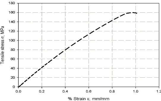
The value of the un-notched nominal strength, considered as the maximum principal stress, is measured as 163 MPa. Besides, the damage evaluation criterion is maximum traction displacement; the maximum crack opening of the composite specimen is experimentally measured as 0.3 mm. Moreover, the swept meshing technique is used to generate a dense mesh using (C3D8R) element type of 1433 elements with approximate global size 2 in the domain as shown in Figure 4. Figure 5 shows the rectangular cracked domain which is yielded from the application of the displacement control boundary conditions at both ends of the rectangular cracked domain (see ure 5 a-b). Critical fracture toughness (𝐺𝐼𝐶) of the delaminated body is measured as the area under the cohesive zone model.
The maximum crack opening is considered as the damage evaluation and it is calculated using the following equation [28]:
2 2 2
n n s t
δ = δ +δ +δ (1)
where ( 𝛿𝑛,𝛿𝑠 ,𝛿𝑡) is normal, shear and tangential components of the traction and separation to the cohesive surface, respectively.
Figure 4. X-FEM Mesh domain
Figure 5. X-FEM a) interaction domain, b) B. C domain
4. Results and Discussion
The observed fluctuations in the curve may be due to fiber breaking.
The stress-strain relation for the center cracked test specimens, with dimensions of width=45 mm, gauge section length; L=90 mm and thickness; t=1.5 mm, respectively, is shown in Figure 8. The value of failure stress was calculated for all the specimens and the average value was found to be 160.9 MPA. The fracture toughness (KIC) was also calculated by substituting in Eq. (2), the
values of (σ) and center crack length (2a) 15 mm. The result showed the fracture toughness (KIC) equal to
34.92 𝑀𝑃𝑎√𝑚 with standard deviation (SDV) of 0.5556 𝑀𝑃𝑎√𝑚.
.
IC a
K a sec
w
π
σ π
=
(2)
It is observed in Figure 7-b, that delamination occurred at copper glass fiber interface of the composite panel. It was probably, due to that weakening of epoxy resin adhesive used in manufacturing the laminates panel and there was net tension in laminates panel’s specimens.
Figure 6. Tensile stress-strain curve for composite material (un notched specimens)
Figure 7. Mode of failure image a) tension test, b) center cracked plate
Figure 9. Variation of predicted fracture toughness with crack opening displacement; COD
Figure 10. Variation of predicted cohesive stress at crack face with crack opening displacement; COD
Figure 12. Stress contours a) Displacement, b) Von-Mises
Figure 9 shows validation of critical stress intensity factor (KIC) extracted from the finite element model and
the one measured experimentally. It is obvious that the two values are very close, this can be attributed to that linear X-FEM based on the real properties of the composite panel. This curve is the average of 5 contour integrals. The cohesive stress which was implemented in the damage criteria in the simulation is 160 MPa, the predicted value is very close and gives good agreement with the implemented value as shown in Figure 10. PHILSM functions are used to define and show the location of crack inside a body as clearly shown in Figure 11-a. In Figure 11 b, STUTUS X-FEM shows the extent of damage or “cracking” inside an element. In other words, XFEM has three important parameters: (i) PHILSM (ϕ); describes the face of fracture, (ii) PSILSM (ψ); describes the forehead of initial fracture, and (iii) STATUSXFEM; which specifies whether the item is full, partial or not cracked. The stress contours are shown in Figure 12; the displacement contour illustrates the maximum displacement at the location of tension, while maximum Von-Mises stress at the crack tip.
5. Conclusion
The fracture toughness of Copper/Glass-Reinforced Epoxy Laminate Composites was investigated both experimentally, using center notch specimens, as well as numerically by the extended finite element method. From this investigation, it may conclude that center notch specimen can be standardized as a dependent test for the hybrid composite panel. Moreover, the finite element model effectively predicts the fracture toughness of this composite and gives good agreement with the experimental results of fracture toughness. On the other hand, the thin copper film gives an insignificant effect on the trend of the tensile properties of the composite panel whereas, it gives an increase in composite strength, therefore, linear behaviors are the global trend.
References
[1] M. K. Hassan, T. Torii, and K. Shimizu, "Fatigue fracture behavior of MEMS Cu thin films."
[2] A. Wymysłowski, B. Vandevelde, and D. Andersson, "Thermal, mechanical and multi-physics simulation and experiments in micro-electronics and micro-systems," Microelectronics Reliability, vol. 47, pp. 159-160, 2007.
[3] R. Ballarini, R. Mullen, H. Kahn, and A. Heuer, "The fracture toughness of polysilicon microdevices," MRS Online Proceedings Library Archive, vol. 518, 1998.
[4] H. D. Espinosa and B. Peng, "A new methodology to investigate fracture toughness of freestanding MEMS and advanced materials in thin film form," Journal of microelectromechanical systems, vol. 14, pp. 153-159, 2005.
[5] I. Chasiotis and W. G. Knauss, "The mechanical strength of polysilicon films: Part 1. The influence of fabrication governed surface conditions," Journal of the Mechanics and Physics of Solids, vol. 51, pp. 1533-1550, 2003.
[6] H. Kahn, N. Tayebi, R. Ballarini, R. Mullen, and A. Heuer, "Fracture toughness of polysilicon MEMS devices," Sensors and Actuators A: Physical, vol. 82, pp. 274-280, 2000.
[7] W. Sharpe, B. Yuan, and R. Edwards, "Fracture tests of polysilicon film," MRS Online Proceedings Library Archive, vol. 505, 1997. [8] T. Tsuchiya, J. Sakata, and Y. Taga, "Tensile strength and fracture
toughness of surface micromachined polycrystalline silicon thin films prepared under various conditions," MRS Online Proceedings Library Archive, vol. 505, 1997.
[9] M. Y. Abdellah, "Essential work of fracture assessment for thin aluminium strips using finite element analysis," Engineering Fracture Mechanics, vol. 179, pp. 190-202, 2017/06/15/ 2017. [10] Z. P. Bazant and J. Planas, Fracture and size effect in concrete
and other quasibrittle materials vol. 16: CRC press, 1997. [11] Z. P. Bažant, "Size effect in blunt fracture: concrete, rock, metal,"
Journal of Engineering Mechanics, vol. 110, pp. 518-535, 1984. [12] P. S. Shinde, K. Singh, V. Tripathi, P. Sarkar, and P. Kumar,
"Fracture toughness of thin aluminum sheets using modified single edge notch specimen," International Journal of Engineering and Innovative Technology (IJEIT) Volume, vol. 1, 2012.
[13] M. K. Hassan, Y. Mohammed, T. Salem, and A. Hashem, "Prediction of nominal strength of composite structure open hole specimen through cohesive laws," Int. J. Mech. Mech. Eng. IJMME-IJENS, vol. 12, pp. 1-9, 2012.
[14] Y. Mohammed, K. Mohamed, and A. Hashem, "Finite element computational approach of fracture toughness in composite compact-tension specimens," International Journal of Mechanical and Mechatronics Engineering, vol. 12, pp. 57-61, 2012.
[15] M. Y. Abdellah, "Comparative Study on Prediction of Fracture Toughness of CFRP Laminates from Size Effect Law of Open Hole Specimen Using Cohesive Zone Model," Engineering Fracture Mechanics, vol. 187, 2018.
[16] M. Q. K. Mohammed Y. Abdellah, Mohammad S. Alsoufi, Nouby M. Ghazaly, G. T. Abdel-Jaber, "Mechanical Properties of Lab Joint Composite Structure of Glass Fiber Reinforced Polymers," Materials Sciences and Applications, vol. 8, pp. 553-565, 2017. [17] M. Y. A. Mohamed K. Hassan, Tareq S. ElAbiadi, Ahmed F.
[18] M. Y. Abdellah, "Delamination Modeling of Double Cantilever Beam of Unidirectional Composite Laminates," Failure analysis and prevention, 2017.
[19] H. A. EI-Aini, Y. Mohammed, and M. K. Hassan, "Effect of mold types and cooling rate on mechanical properties of Al alloy 6061 within ceramic additives," in Second International conference of Energy Engineering; ICEE-2, 2010.
[20] A. Standard, "Standard test method for tensile properties of polymer matrix composite materials," ASTM D3039/D 3039M, 1995.
[21] C. Soutis, P. Curtis, and N. Fleck, "Compressive failure of notched carbon fibre composites," in Proceedings of the Royal Society of London A: Mathematical, Physical and Engineering Sciences, 1993, pp. 241-256.
[22] T. Kuno, Y. Yamagishi, T. Kawamura, and K. Nitta,
"Deformation mechanism under essential work of fracture process in polycyclo-olefin materials," Express Polym Lett, vol. 2, pp. 404-412, 2008.
[23] Y. Mohammed, M. K. Hassan, and A. Hashem, "Effect of stacking sequence and geometric scaling on the brittleness number of glass fiber composite laminate with stress raiser," Science and Engineering of Composite Materials, vol. 21, pp. 281-288, 2014. [24] T. Belytschko and T. Black, "Elastic crack growth in finite
elements with minimal remeshing," International journal for numerical methods in engineering, vol. 45, pp. 601-620, 1999. [25] J. M. Melenk and I. Babuška, "The partition of unity finite
element method: basic theory and applications," Computer methods in applied mechanics and engineering, vol. 139, pp. 289-314, 1996.
[26] D. Datta, "Introduction to eXtended Finite Element (XFEM) Method," arXiv preprint arXiv: 1308. 5208, 2013.
[27] N. S. K. Montasser Dewidar, Mohammed Y. Abdellah, Ayman M.M. Abdelhaleem, "Finite element modeling of mechanical properties of titanium foam and dental application," in The third international conference on energy engineering (ICEE), 2015. [28] A. V. ABAQUS, "6.9 Documentation," Providence, RI: Dassault
![Table 1. Chemical composition of the copper film and base glass fiber [1]](https://thumb-us.123doks.com/thumbv2/123dok_us/1222443.2083230/2.595.52.550.371.767/table-chemical-composition-copper-film-base-glass-fiber.webp)