DEVELOPMENT OF A MICROFLUIDIC IMMUNOASSAY FOR DETERMINATION OF KINASE PHOSPHORYLATION
Joseph Carl Gaiteri
A dissertation submitted to the faculty of the University of North Carolina at Chapel Hill in partial fulfillment of the requirements for the degree of Doctor of Philosophy in the
Department of Chemistry.
Chapel Hill 2014
ABSTRACT
Joseph Carl Gaiteri: Development of a Microfluidic Immunoassay for Determination of Kinase Phosphorylation
(Under the direction of J. Michael Ramsey)
Extracellular signal-related kinases 1 and 2 (ERK1/2) are signaling proteins involved in cell survival and proliferation and are overactive/phosphorylated (forming pERK1/2) in
approximately 1/3 of human cancers. Measuring pERK1/2:ERK1/2 is therefore common in cancer-related research, but conventional methods are some combination of slow, expensive, and labor-intensive, and large samples are often required. Microfluidic devices offer the possibility of determining pERK1/2:ERK1/2 rapidly, with lower costs, and with substantially reduced labor and reagent requirements compared to conventional methods. This would facilitate more
expedient medical decisions and increase experimental throughput in research that requires determining pERK1/2:ERK1/2, such as that related to tumor cell signaling and anti-cancer drug development. This dissertation describes the development of a microfluidic immunoassay for determining the ratio of pERK1/2:ERK1/2 in human cell lysate.
Early experiments used antibody-coated beads loaded into chips with
was determined that the process of loading beads into the PDMS arrays was mechanically damaging their capture antibodies.
The next chapter introduced a new chip design for performing pERK1/2:ERK1/2 assays without harsh mechanical loading. These chips were used to optimize assay conditions and determine pERK1/2:ERK1/2 in human Jurkat cell lysate at physiologically relevant
concentrations. Further improvement of the assay called for automation to minimize labor/user interaction during experiments, and this required valves to control fluid flow on-chip. The next chapter therefore focused on developing computer-controlled, Peltier-based freeze-thaw valves for microfluidic chips. In the final chapter, these valves were coupled with a chip design for assaying up to 8 samples simultaneously. These chips could be used to perform multiple
replicate measurements of a sample or to produce a calibration curve on the same device used to measure samples. Finally, the 8-sample chips were used with the freeze-thaw valves to
ACKNOWLEDGEMENTS
TABLE OF CONTENTS
LIST OF TABLES ... xii
LIST OF FIGURES ... xiii
LIST OF ABBREVIATIONS AND SYMBOLS ... xvii
CHAPTER 1: INTRODUCTION ... 1
1.1 Background ... 1
1.2 General microfluidics, point-of-care devices, and poly(dimethylsiloxane)... 3
1.3 Microfluidic valving ... 6
1.4 Immunoassays ... 8
1.5 ERK1/2 signaling pathway ... 11
1.6 Research goals ... 13
1.7 References ... 15
CHAPTER 2: BEAD-BASED SANDWICH IMMUNOASSAY FOR pERK1/2 AND TOTAL ERK2 ... 23
2.1 Introduction ... 23
2.2 Materials and methods ... 27
2.2.1 Materials and reagents ... 27
2.2.2 Bead-antibody coupling ... 28
2.2.2.1 Coupling procedure for non-magnetic beads ... 29
2.2.2.2 Coupling procedure for magnetic beads ... 30
2.2.3.1 Fabrication of silicon masters ... 32
2.2.3.2 PDMS chip fabrication ... 33
2.2.4 Loading beads into microarrays ... 34
2.2.5 Data collection ... 35
2.2.6 Data analysis ... 35
2.2.7 Sandwich assay procedure ... 36
2.3 Results and discussion ... 37
2.3.1 Fluorophore selection... 37
2.3.2 Reagent incubation time and concentration ... 37
2.3.3 Development of pERK1/2 assay ... 39
2.3.4 Protocol development for dual-dAb pERK2:ERK2 assay ... 40
2.4 Conclusions ... 42
2.5 Figures... 44
2.6 References ... 56
CHAPTER 3: INVESTIGATING SOURCES OF ERROR IN MICROBEAD ARRAY ASSAYS ... 59
3.1 Introduction ... 59
3.2 Materials and methods ... 61
3.2.1 Materials and reagents ... 61
3.2.2 Fabrication of multi-array chips and 100-bead arrays ... 62
3.2.3 Fabrication of simple column chips ... 63
3.2.4 Fabrication of stage-weir chips ... 65
3.2.5 Assay procedures ... 65
3.3 Results and discussion ... 66
3.3.1 Assay with multi-array chips ... 66
3.3.2 Assay with internal standard ... 67
3.3.3 Off-chip incubations to isolate error sources ... 68
3.3.4 Assay with off-chip dye incubation ... 69
3.3.5 Assays with simple column chips ... 71
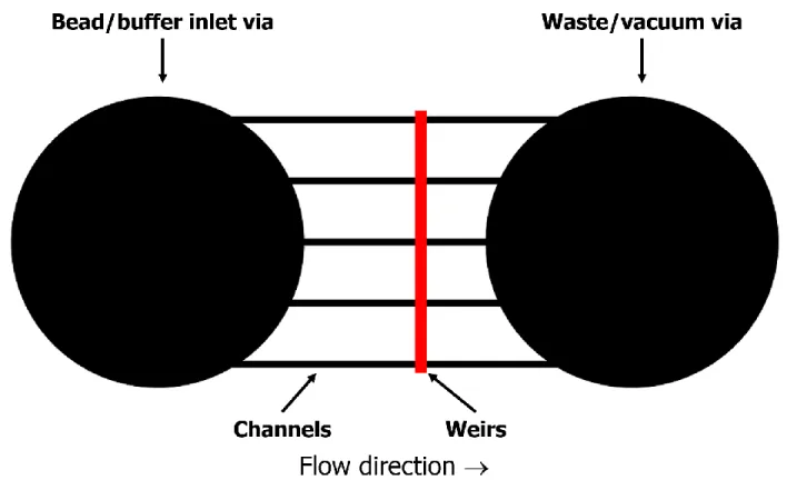
3.3.6 Assays with stage-weir chips ... 71
3.3.7 Mechanical damage assays ... 72
3.4 Conclusions ... 74
3.5 Figures... 75
3.6 References ... 89
CHAPTER 4: DEVELOPMENT OF A pERK1/2:ERK1/2 SANDWICH IMMUNOASSAY USING ANTIBODY-BOUND BEADS AND MONOLAYER CHIPS ... 90
4.1 Introduction ... 90
4.2 Materials and methods ... 94
4.2.1 Materials and reagents ... 94
4.2.2 Design and fabrication of flow-frit chips ... 95
4.2.3 Flow-frit chip assay method... 96
4.2.4 Data analysis ... 96
4.2.5 Cell culture ... 97
4.2.6 Cell lysis... 97
4.3 Results and discussion ... 98
4.3.1 Preliminary pERK2 and nERK2 assays with stage-weir chips ... 98
4.3.3 On-chip sample incubation ... 102
4.3.4 Optimization of flow-frit assay steps ... 103
4.3.5 Detection of total ERK1... 104
4.3.6 Simultaneous nERK1 and nERK2 detection on-chip ... 105
4.3.7 Cell lysis assay ... 105
4.4 Conclusions ... 106
4.5 Tables and figures ... 108
4.6 References ... 124
CHAPTER 5: DEVELOPMENT OF FREEZE-THAW VALVING SYSTEM FOR MICROFLUIDIC DEVICES ... 126
5.1 Introduction ... 126
5.2 Materials and methods ... 128
5.2.1 Materials and reagents ... 128
5.2.2 Mixing tee chip design and fabrication ... 130
5.2.3 Valve construction ... 131
5.2.4 Peltier control electronics ... 132
5.2.5 Image collection ... 133
5.3 Results and discussion ... 133
5.3.1 Temperature characterization of valving system ... 134
5.3.2 Temperature and thermal characterization of valve Peltier ... 136
5.3.3 Freeze/thaw valve efficacy with single mixing tee chips ... 137
5.3.4 Double mixing tee chips and reproducibility of valve times ... 139
5.3.5 Verification of sustained valve closure over time... 141
5.5 Figures... 143
5.6 References ... 160
CHAPTER 6: ASSAYS WITH MULTI-SAMPLE CHIPS AND FREEZE-THAW VALVES AND FUTURE DIRECTIONS ... 162
6.1 Introduction ... 162
6.2 Materials and methods ... 164
6.2.1 Materials and reagents ... 164
6.2.2 Design & fabrication of freeze-thaw chips ... 166
6.2.3 Assay procedures with optimization chips ... 168
6.2.4 Data analysis ... 169
6.3 Results and discussion ... 169
6.3.1 Automated chip design and the use of plug beads ... 169
6.3.2 Consistency of fluid flow from chip to chip ... 171
6.3.3 Sample channel sealing with Pluronic F-127... 172
6.3.4 Initial assays with Pluronic F127-sealed chips ... 174
6.3.5 On-chip incubations ... 175
6.3.6 pERK1/2:ERK1/2 assay with full freeze-thaw valve chip and automated fluid delivery ... 177
6.4 Conclusions and future directions ... 178
6.5 Figures... 182
LIST OF TABLES
LIST OF FIGURES
Figure 2.1. Photograph of saliva cytokine chip filled with ink for visualization... 44
Figure 2.2. Schematic of 8-channel chip with array ... 45
Figure 2.3. Schematic of single-analyte sandwich immunoassay... 46
Figure 2.4. Schematic of single-dAb strategy for determining pERK1/2:ERK1/2 ... 47
Figure 2.5. Dual-dAb strategy for determining pERK1/2:ERK1/2 in which pERK1/2 is determined first ... 48
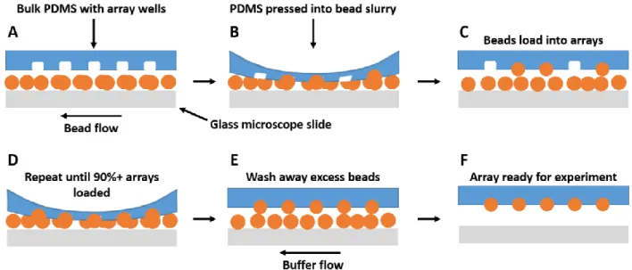
Figure 2.6. Schematic of loading process for PDMS arrays ... 49
Figure 2.7. Encoding image and corresponding assay image from a 3-bead assay ... 50
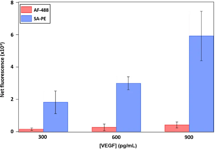
Figure 2.8. Comparison of fluorescent reporter complexes used for detection in VEGF assay .. 51
Figure 2.9. Comparison of reagent incubation strategies ... 52
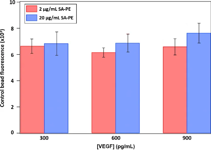
Figure 2.10. Comparison of non-specific binding on control beads from two different concentrations of fluorescent dye ... 53
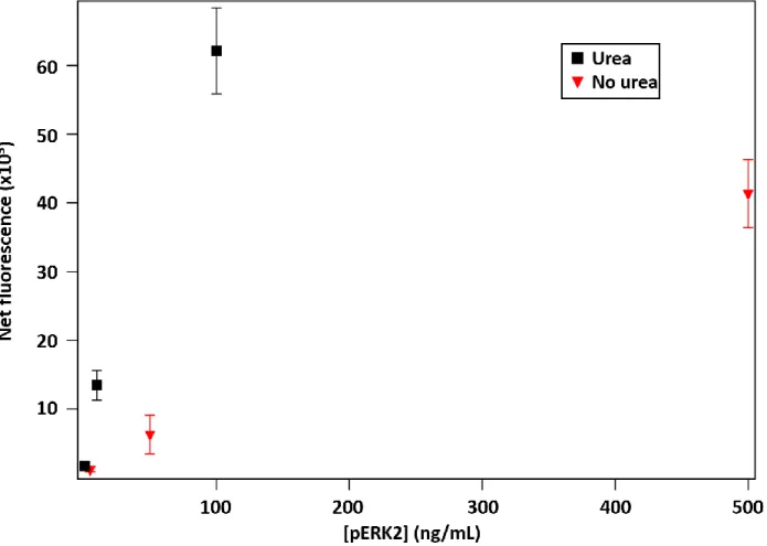
Figure 2.11. Comparison of pERK2 assay results with and without urea in the assay buffer ... 54
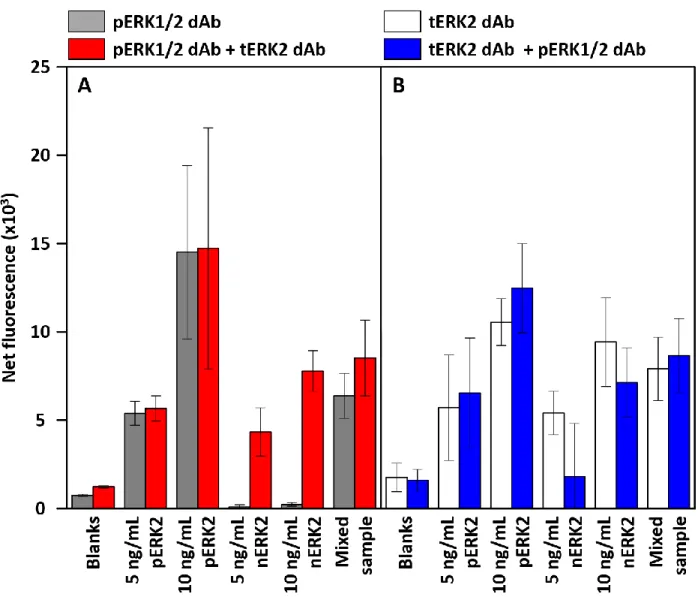
Figure 2.12. Results from pERK2:ERK2 protocol development experiment ... 55
Figure 3.1. Schematic of a multi-array chip ... 75
Figure 3.2. Top-down schematic of simple column chip ... 76
Figure 3.3. Cutaway schematic of a simple column chip ... 77
Figure 3.4. Schematic of stage-weir chips showing beads in the viewing zone packed against a 6-µm weir ... 78
Figure 3.5. pERK2:VEGF signal ratio with pERK2 concentration using VEGF as an internal standard ... 79
Figure 3.6. Assay images of a 100-bead array from large-scale variance experiment ... 80
Figure 3.7. Fluorescence images of four 1,024-bead arrays after VEGF sandwich immunoassays ... 81
Figure 3.8. Encoding image and fluorescence assay image from simple column chip ... 82
Figure 3.10. Fluorescence signal with viewing stage depths of three stage weir chips, plus one
additional 6.7-µm set that had been pressed upon by the wand ... 84
Figure 3.11. Fluorescence assay image from a stage-weir chip and fluorescence assay image from a stage-weir channel in which the bead column was pressed upon by the magnetic loading wand prior to imaging ... 85
Figure 3.12. Fluorescence assay signal comparing the reproducibility across four separate tubes with identical assay conditions ... 86
Figure 3.13. Fluorescence signal with the number or presses or grinds used to load beads... 87
Figure 3.14. Fluorescence signal with number of presses or grinds used to load beads ... 88
Figure 4.1. Photographs of flow-frit chips filled with ink for visualization ... 109
Figure 4.2. Side view schematic of flow-frit chip with bead monolayer and white light microscope image of chip with bead bed ... 110
Figure 4.3. Data analysis process for flow-frit chips ... 111
Figure 4.4. Net fluorescence intensity with pERK2 concentration and stage-weir chips ... 112
Figure 4.5. Net fluorescence intensity with nERK2 concentration taken with stage-weir chips ... 113
Figure 4.6. Net fluorescence intensity with pERK2:ERK2 ratio taken with stage-weir chips .. 114
Figure 4.7. pERK2:ERK2 fluorescence ratio with %pERK in the sample using a stage weir device ... 115
Figure 4.8. Results from initial attempt at on-chip incubation with packed bead bed in flow-frit chips ... 116
Figure 4.9. Results of experiment evaluating each configuration of flow bed features with off-chip sample incubations ... 117
Figure 4.10. Fluorescence response with pERK2 concentration using on-chip sample incubation ... 118
Figure 4.11. Fluorescence signal with dAb incubation time ... 119
Figure 4.12. Fluorescence signal with increasing SA-PE incubation time ... 120
Figure 4.15. pERK1/2:ERK1/2 fluorescence ratio with increasing %pERK
in standards and cell lysate samples ... 123
Figure 5.1. Schematic of a 2-tier cascaded Peltier setup ... 143
Figure 5.2. Schematic of mixing tee chip used for valve development ... 144
Figure 5.3. Schematic of triple mixing tee chip used to study all four valves ... 145
Figure 5.4. Photographs of water block with mounted base Peltier ... 146
Figure 5.5. Triple mixing tee chip placed on freeze-thaw valve platform ... 147
Figure 5.6. Imaging setup for simultaneous fluorescence/thermal studies ... 148
Figure 5.7. Schematic for thermal camera study of base Peltier at various currents ... 149
Figure 5.8. Thermal images of base Peltier at 5.1 A showing new mounting locations for the valves ... 150
Figure 5.9. Valve temperatures as a function of their duty cycle and polarity ... 151
Figure 5.10. Visualization schematic for valve states in mixing tee ... 152
Figure 5.11. Fluorescence images of freeze event ... 153
Figure 5.12. Fluorescence images showing thaw event ... 154
Figure 5.13. Time series of freezing and thawing with inset from thermal camera ... 155
Figure 5.14. Event times for multiple freeze/thaw cycles of the same valve ... 156
Figure 5.15. Event times for multiple freeze/thaw cycles in which the system was held at -2.5 °C for 20 s between each event ... 157
Figure 5.16. Event times for multiple freeze/thaw cycles in which the system was shut off for 20 s between each event ... 158
Figure 5.17. Time series of sustained valve closure experiment ... 159
Figure 6.1. Schematic of 8 sample chip ... 182
Figure 6.2. Three variations on the multi-sample chip design used for assay development and optimization ... 183
Figure 6.3. Schematic of WEKA analysis ... 184
Figure 6.6. Optimization chip before and after Pluronic F-127 sealing of sample channels ... 186 Figure 6.7. Fluorescence signal with [pERK2] with linear fits from experiments comparing
fluorescence from chips with and without PF-127 sealed sample channels ... 187 Figure 6.8. The three steps involved in preparing a chip for incubation with
the assay reagents ... 188 Figure 6.9. pERK1/2:ERK1/2 fluorescence ratio with %pERK with on-chip
sample incubations ... 189 Figure 6.10. pERK1/2:ERK1/2 fluorescence ratio with %pERK after inclusion
of pERK1 in the calibration standards ... 190 Figure 6.11. pERK1/2:ERK1/2 fluorescence ratio with %pERK using the
LIST OF ABBREVIATIONS AND SYMBOLS
A Ampere
Ab Antibody
AF488 Alexa Fluor® 488, streptavidin conjugate BOE Buffered oxide etchant
BP Base Peltier
BSA Bovine serum albumin CAb Capture antibody CCD Charge-coupled device CE Capillary electrophoresis
cm Centimeter
CML Chronic myelogenous leukemia CV Coefficient of variance
dAb Detection antibody DC Direct current df Depth of field
DI Deionized
DRIE Deep reactive-ion etching
EDAC 1-ethyl-3-(-3-dimethylaminopropyl) carbodiimide hydrochloride EDTA Ethylene diamine tetraacetic acid
ERK1 Extracellular signal-related kinase 1 (refers to both phospho-forms of ERK1) ERK2 Extracellular signal-related kinase 2 (refers to both phospho-forms of ERK2)
FIB Focused ion beam
FTV Freeze-thaw valve
g Gram
h Hour
Hz Hertz
IgG Immunoglobulin-G
IR Infrared
IU International unit λem Emission wavelength λex Excitation wavelength LC Liquid chromatography LOC Lab-on-a-chip
LOD Limit of detection
M Molar
mAb Monoclonal antibody
MAPK Mitogen-activated protein kinase
MEK1/2 Mitogen-activated protein kinase kinases 1 and 2 MES 2-(N-morpholino)ethanesulfonic acid
µg Microgram
µL Microliter
µM Micromolar
mg Milligram
mJ Millijoule
mL Milliliter
mm Millimeter
mM Millimolar
min Minute
µTAS Micro total chemical analysis system NA Numerical aperture
NaCl Sodium chloride
ng Nanogram
nm Nanometer
nM Nanomolar
nERK1 Non-phosphorylated ERK1 nERK2 Non-phosphorylated ERK2
Ω Ohm
pAb Polyclonal antibody PBS Phosphate-buffered saline PCR Polymerase chain reaction PDMS Poly(dimethylsiloxane) PEG Polyethylene glycol
pERK1 Phospho-ERK1
PF-127 Pluronic F-127
PMA Phorbol 12-myristate 13-acetate
pg Picogram
pM Picomolar
PMSF Phenylmethanesulfonyl fluoride POC Point-of-care
PWM Pulse-width modulation
rcf Relative centrifugal force, 1 x gravity rpm Revolutions per minute
%RSD Percent relative standard deviation
s Second
S1813 Shipley 1813 photoresist SA-PE Streptavidin-B-phycoerythrin SA-QD Streptavidin-quantum dot S/N Signal-to-noise ratio
Si Silicon
Sulfo-NHS N-hydroxysulfosuccinimide TBS Tris-buffered saline
tERK1 Total ERK1 tERK2 Total ERK2
UV Ultraviolet
V Volt
VP Valve Peltier
CHAPTER 1
INTRODUCTION 1.1 Background
Benchtop assays that yield accurate, reproducible results now exist for a vast range of medical and research purposes. However, these conventional assays can be slow and labor-intensive. In research terms, this leads to lower experimental throughput, while in medical terms, this often increases the time required to make healthcare decisions. These delays are exacerbated by the fact that medical tests are often performed at centralized facilities, requiring the samples to be packaged and shipped with the results communicated back to the healthcare provider and then the patient. In recent decades, these considerations have led to a trend towards miniaturizing conventional benchtop assays. Ideally, these miniaturized devices would meet or exceed the performance of their conventional counterparts in terms of accuracy, reproducibility, and sensitivity. They should also offer further advantages including portability, reduced
reagent/sample consumption and lower cost in general, and greater speed due to the reduced incubation/migration times that come with the small dimensions of the miniature devices.1–7
sample in approximately thirty seconds, much faster than conventional microscope-based hemocytometers.10
The speed and accuracy of miniaturized assays make them well-suited to the domain of cancer research and medicine, where time – in terms of discovering treatments and making medical decisions related to a patient’s ongoing therapy – is of the utmost concern. One of the fundamental characteristics of cancer is the dysregulation of the cell signaling process on multiple fronts such that cancer cells have overcome the normal processes that tightly regulate tissue growth.11,12 In approximately one-third of human cancers, the extracellular signal-related kinase 1 and 2 (ERK1/2) signaling cascade is involved in this dysregulation.13 ERK1 and ERK2 are proteins involved in regulating fundamental processes such as apoptosis and growth and are activated by dual phosphorylation. Upon becoming phospho-ERK1/2 (pERK1/2), they migrate to the cell nucleus and activate transcription factors and genes related to growth and
proliferation.13–17 Cancer-related mutations in the ERK1/2 pathway often lead to excessive ERK1/2 phosphorylation and activity.13–16,18–21 It is therefore a pathway whose activity is
commonly monitored in cancer research. Also, many drugs have been and are being designed to inhibit mutationally activated proteins in the ERK1/2 cascade.21 The most successful of these is imatinib (Gleevec®), a drug that inhibits the kinase domain in the mutant BCR-ABL kinase (upstream from ERK1/2) in patients with chronic myelogenous leukemia (CML). Prior to the invention of imatinib and related drugs in its class, the prognosis for CML was extremely poor; it is now considered highly treatable.22
However, these mutant proteins sometimes acquire further mutations that prevent their inhibitory drugs from binding.21,23 Monitoring the extent of ERK1/2 phosphorylation is,
response to a new one. Various methods24–28 currently exist for determining pERK1/2 and/or total ERK1/2 in cell lysate. These include the Western Blot, enzyme-linked immunosorbent assay (ELISA), and AlphaScreen™, Li-Cor®, and Meso-Scale Discovery® systems. These methods are effective, but each has one or more of the following drawbacks: being labor-intensive, requiring large samples (hundreds of thousands to millions of cells in some cases), requiring long incubation times (up to overnight), and being difficult to automate or not being automatable at all. A miniaturized or microfluidic device for determining pERK1/2:ERK1/2 in a sample can potentially solve many of these issues. This is desirable from a medical standpoint, as the time required to make a crucial medical decision may be reduced. It is also desirable from a scientific standpoint, as it can increase experimental throughput in studies that involve
determining cellular pERK1/2 expression. Such research includes examining cell signaling in tumors under various circumstances or studying the effects of kinase inhibitor drugs on the ERK1/2 pathway.16,20,21,29 The remainder of this chapter will provide a general overview of the field of microfluidics and explain why it is well-suited for addressing this problem.
Immunoassays, the central technique in the device, will then be reviewed. Finally, the ERK1/2 signaling pathway will be explained in greater detail and the research goals for the project outlined.
1.2 General microfluidics, point-of-care devices, and poly(dimethylsiloxane)
developed in the microelectronics industry also contributed to the growth of microfluidics, as photolithography and other techniques were adapted to fabricate microfluidic devices. These techniques make it possible to create micrometer- or nanometer-scale features in silicon and glass. It was in these materials1,2 that much of the early work in microfluidics was conducted using such techniques as liquid chromatography (LC) and capillary electrophoresis (CE).2,30–33
In 1990, Manz and co-workers30 proposed the possibility of constructing a micro total chemical analysis system (µTAS), also called a lab-on-a-chip (LOC).2,3,30,34 A LOC would incorporate all the steps from a conventional benchtop technique into a single miniaturized device. These steps could include sample pretreatment,31,35 analysis through techniques such as immunoassays,36,37 the polymerase chain reaction,35,38 or CE,31,39–41 and detection of the results through optical,2,31,37 electrochemical,4,42,43 mass spectrometric,39,40 or other means.1,2,5,6 Ideally, all this would be possible while maintaining or exceeding the performance of the corresponding conventional technique. In addition,1,2,5,6 the high surface area-to-volume ratio reduces
incubation or reaction times due to the reduced time required for molecules to diffuse across the dimensions of the device, thus reducing analysis times.4 Microfluidic devices also have the advantage of requiring significantly lower volumes of sample and reagent than conventional techniques.1–3,7 This reduces costs given the lowered consumption of expensive reagents such as enzymes and monoclonal antibodies, and it enables the analysis of samples of which only micro-quantities are available, as is the case with many biological samples.44,45
result with minimal or no additional interaction with the system.1,2,47 These devices are ideal for point-of-care (POC) diagnostics, where a test is performed at or near the site of patient care.48,49 Performing analyses at the POC instead of a separate testing facility can reduce the results’ turnaround time from days or weeks to minutes or hours.7,48–50 Devices such as these have the potential to improve a patient’s outcome in time-critical decisions as well as reduce costs associated with labor and shipping/handling the samples.49,50 A recent example of POC devices is the microfluidic paper-based class of devices developed by the Whitesides group, which are usable in a low- or zero-resource setting.51 As the results of these devices can be captured with a cell phone camera and transmitted anywhere in the world for diagnosis, these devices can bring healthcare to places where there are no physicians or other medical professionals.52
directly from molds consisting of photoresist patterned on a substrate such as a silicon wafer.61–63 After a device is fabricated in PDMS, access holes (vias) to the channels can be cut from the bulk material and the channels irreversibly sealed by bonding the PDMS to glass following plasma treatment.36,53,54 The bonded device may then be used in an experiment or its surface modified64,65 if necessary prior to use.
1.3 Microfluidic valving
In LOC devices, multiple solutions are typically used simultaneously, so valves play an important role in controlling the fluid flow throughout the chip by opening/closing channels or otherwise modulating the flow direction. Some valves are closed until intentionally opened and are referred to as “normally-closed,” while others are generally open and are referred to as “normally-open.” Many valving strategies have been demonstrated, one of the earliest of which was the electrokinetic valve.31,41,66–68 These are normally-closed valves in which voltages applied to channels are used to dispense plugs of sample through electrokinetic flow. Major types of electrokinetic valves include the double-T valve,33,69 pinched valve,67,70,71 and gated valve.31,41,68 The volume of sample delivered through each injection will primarily be a function of either the spatial dimensions of the chip (for pinched and double-T valves) or the field
strength and duration of the injection (for gated valves).67 Depending on the chip design, electrokinetic valves may require only a single voltage source while exhibiting excellent reproducibility (<0.5% RSD) in the sample volumes delivered.41
reversible given a change in the stimulus. Generally, valving is accomplished when the posts swell to occlude the channel they occupy, but if fluidic isolation of the analysis channels is a requirement, it is also possible for an expanding post to deflect an impermeable PDMS layer to close an adjacent channel.73,74
The final hydrogel example above is also an example of a larger class of valves known as pinch valves.37,55–57,61,62,76,77 These consist of a membrane made from an elastomeric material such as PDMS that is deflected to open or close a channel. Several primary means of controlling the valve exist. Pneumatic actuation is used in one of the most well-known types of microfluidic valves, the Quake-style valve.55–57 These are normally-open valves in which a thin (~30 µm) membrane of PDMS separates a fluidic channel and a pneumatic channel in a multilayer chip. Pressure is applied through the pneumatic channel to deflect the PDMS membrane into the fluidic channel, closing it. A similar design adds a post on the fluidic side of the PDMS membrane to make the valve normally-closed, and negative pressure is used to pull the
membrane into the pneumatic channel and open the valve.77 Quake-style valves can be actuated at approximately 100 Hz, enabling them to act as a peristaltic pump when multiple valves are arranged sequentially in the same channel.55 Pinch valves can also be actuated through
mechanical rather than pneumatic pressure. The Whitesides group has demonstrated numerous examples of this, include manually-actuated screw valves and computer-driven solenoid
valves.61,62 A recent device developed by the Ramsey group in collaboration with the Walt group also utilizes computer-controlled normally-closed pinch valves.37
Thermal actuation is another means of controlling fluid flow in microfluidic channels. The use of paraffin wax is one such method of thermally-driven valving.78–80 Paraffin is
close normally-open channels by melting the wax in both reversible and irreversible
configurations.78,79 Paraffin can also be used in a normally-closed configuration if a solid plug initially seals a channel but opens the channel upon heating.80 Finally, a type of thermal valve that does not require extra material inside the device is the freeze-thaw valve.63,81–84 This strategy uses an external cooling source to freeze a segment of a microfluidic channel, thus stopping flow. Early examples of freeze-thaw valves used low-temperature fluids such as liquid nitrogen81 or carbon dioxide82,83 to induce freezing, while thawing was initiated by removal of the coolant. A freeze-thaw strategy that is recently emerging in the literature utilizes Peltier devices to effect freezing and thawing.63,84 Peltiers consist of alternating semiconductor pellets sandwiched between two insulating layers.85 The application of voltage creates a temperature gradient across the device, and the use of multiple Peltiers stacked on top of one another can generate successively lower temperatures that are sufficiently cold to rapidly freeze aqueous solutions in microfluidic channels. They can also generate heat for thawing/opening a channel if their voltage is reversed. Peltiers are easily computer-controlled, indefinitely reusable,
inexpensive, compatible with a wide range of materials, and do not require the manipulation of high-pressure gases.63
1.4 Immunoassays
immunoassays, sample analytes are incubated along with labeled antigens (most commonly more analyte molecules) such that the unlabeled antigens compete with the labeled antigens for
binding sites on the CAbs. Measurements are therefore made of sites unoccupied by the sample analytes and the signal is inversely proportional to the sample concentration.
The other major type is non-competitive immunoassays, which usually takes the form of a “sandwich assay” because the analyte molecules are sandwiched between two antibodies. Here, analyte molecules are bound by CAbs before a second detection antibody (dAb) is
incubated that completes the sandwich by binding to another epitope (binding site). These dAbs are labeled, or are themselves detected with a third labeled antibody following a third incubation, and after excess dAb is washed away, the occupied sites are measured.88,89 These assays have the disadvantage of requiring two antibodies with specificity for two epitopes on the analyte. This two-antibody characteristic means that sandwich assays are rarely suitable for haptens, as immunoglobulin-G (IgG) antibodies are more than two orders of magnitude larger than haptens and steric effects generally preclude sandwich formation.90 However, use of sandwich
immunoassays for proteins is specific enough that it is possible to distinguish between otherwise identical proteins with different post-translational modifications, such as phosphorylation states. Also, sandwich assays tend to be more sensitive than non-competitive assays because the signal is directly proportional to the analyte concentration.42
In particular, fluorescent labels have become extremely popular,42,86 especially in microfluidic systems.92 A wide range of fluorescent labels with varying spectral profiles exist, ranging from small organic molecules to quantum dots. Enzyme labels on dAbs are also used in
immunoassays in enzyme-linked immunosorbent assays (ELISAs).93 In ELISAs, following the washing away of unbound dAb, a substrate for the enzyme is introduced to the system and the enzyme-substrate reaction products are detected. It is also common to utilize detection
antibodies labeled with biotin.42 Biotin binds rapidly and strongly to streptavidin,94 and while the use of biotin has the drawback of requiring an additional incubation step for the detection label, it has several advantages. First, biotin is small (molecular mass = 244 daltons) and can generally be conjugated to antibodies without reducing their activity. Any label that can be conjugated to streptavidin may then be used, and streptavidin may be conjugated to multiple detection labels for further signal amplification.95
peptide used in generating the mAb. Multiple means of accomplishing this are possible, but adding a denaturing agent such as urea98 to the assay buffer may be the simplest.
1.5 ERK1/2 signaling pathway
Profound dysregulation of the cell signaling process is one of the defining characteristics of cancer. In order to become cancerous, cells must acquire characteristics dubbed “hallmarks” by Hanahan & Weinberg.11,12 Among these hallmarks is the ability to continue to survive and proliferate in spite of contrary signals from other cells in their environment. Cancers utilize many strategies11,12 to accomplish this, one of which is the deregulation of the extracellular signal-related kinase 1 and 2 (ERK1 and ERK2, or ERK1/2 collectively) signaling cascade. This pathway is involved in regulating cellular processes such as apoptosis, proliferation, and growth in response to extracellular signals, and its dysregulation presents in approximately 33% of human cancers.13 The ERK1/2 cascade begins with epidermal growth factor receptors (EGFR) at the cell membrane. Signals from EGFR are sent through other membrane proteins to Ras. Signals then travel from Ras to Raf, then to mitogen-activated protein kinase kinases 1 and 2 (MEK1/2). ERK1/2 are themselves activated by MEK1/2. The activation of ERK1/2 consists of dual phosphorylation at one serine and one threonine residue each,14,15 leading to a conformation change and 1,000-fold increase in activity.15 Activated ERK1/2 translocate to the cell nucleus, where they activate transcription factors and genes related to cell survival and proliferation.13,16,17
In this signaling cascade, cancer-related mutations have been documented in EGFR, Ras, and Raf. Notably, Raf is mutationally active in 70% of melanomas and 50% of papillary thyroid cancers, Ras is mutationally active in 90% of pancreatic cancers, 60% of papillary thyroid
cancers, over 50% of carcinomas, up to 50% of pancreatic cancers, and 20% of
glioblastomas.13,16 These mutational activations upstream from ERK1/2 often lead to excessive activation of ERK1/2 to the extent that some tumors are dependent upon ERK1/2 for survival and are “ERK-addicted.”18 Excessive ERK1/2 activation is also seen because of downstream signal amplification, wherein relatively few molecules are needed to activate a relatively large number of molecules further down the signaling cascade.14,99 For example, activation of just 5% of a cell’s Ras molecules has been estimated to be sufficient for fully activating that cell’s ERK1/2.100
Several factors call for the development of assays for determining the phosphorylation extent (pERK1/2:ERK1/2) of ERK1/2. Because of the commonality of mutations in the ERK1/2 cascade leading to elevated ERK1/2 activity, the pERK1/2:ERK1/2 ratio is a useful biomarker in many cases.14,16,19–21 Drugs have been and continue to be developed to inhibit mutationally activated proteins in the pathway by binding to and antagonizing their kinase domains.
However, the mutated proteins sometimes acquire further mutations that prevent the drugs from binding. The pERK1/2:ERK1/2 ratio in these cells is thus a useful diagnostic here as well, as it changes in response to the specific drug and mutation21 and can be used in the monitoring of treatment efficacy. Finally, because they are present at approximately micromolar
ERK1/2 can then be used to determine pERK1/2 and ERK1/2 and thus the pERK1/2:ERK1/2 ratio in cells.29
These strategies and considerations open the door for developing a microfluidic device for determining pERK1/2:ERK1/2 in a sample. Current methods of pERK1/2:ERK1/2
determination (namely the Western Blot) are time- and labor-intensive and can require millions of cells. A device with the advantages of microfluidics – relatively small sample size and reagent consumption, fast incubation times, high sensitivity, and the potential for automation – can provide a substantial improvement over these methods in terms of time and cost.
1.6 Research goals
The goal of this project is to develop a bead-based microfluidic immunoassay device for determining pERK1/2:ERK1/2 in human cell lysate. The microfluidic device would be
automated such that once sample and reagents were added to vias on the microfluidic device, no other user interaction would be needed. Early efforts centering on the selection of fluorophores, optimizing incubation times, determining suitable antibody pairs for a pERK1/2 and ERK2 sandwich immunoassay, and the development of a general on-chip assay protocol are described in Chapter 2. Based on these early results, troubleshooting efforts to improve the reproducibility of the assay to clinically relevant standards are the subject of Chapter 3. The results of Chapter 3 led to an improved chip design investigated in Chapter 4, wherein an on-chip assay for
determining pERK1/2:ERK1/2 in human cell lysate is demonstrated. Chapter 5 focused on automating the assay using a computer-controllable valving method (freeze-thaw valves, FTVs). Finally, a chip design where fluid flow is controlled by automatable FTVs is described in
1.7 References
(1) Whitesides, G. M. The Origins and the Future of Microfluidics. Nature 2006, 442, 368– 373.
(2) Reyes, D. R.; Iossifidis, D.; Auroux, P.-A.; Manz, A. Micro Total Analysis Systems. 1. Introduction, Theory, and Technology. Anal. Chem. 2002, 74, 2623–2636.
(3) Janasek, D.; Franzke, J.; Manz, A. Scaling and the Design of Miniaturized Chemical-Analysis Systems. Nature 2006, 442, 374–380.
(4) Bange, A.; Halsall, H. B.; Heineman, W. R. Microfluidic Immunosensor Systems. Biosens. Bioelectron. 2005, 20, 2488–2503.
(5) Arora, A.; Simone, G.; Salieb-Beugelaar, G. B.; Kim, J. T.; Manz, A. Latest
Developments in Micro Total Analysis Systems. Anal. Chem. 2010, 82, 4830–4847. (6) Dittrich, P. S.; Tachikawa, K.; Manz, A. Micro Total Analysis Systems. Latest
Advancements and Trends. Anal. Chem. 2006, 78, 3887–3908.
(7) Weigl, B.; Domingo, G.; Labarre, P.; Gerlach, J. Towards Non- and Minimally
Instrumented, Microfluidics-Based Diagnostic Devices. Lab Chip 2008, 8, 1999–2014. (8) Olansky, L.; Kennedy, L. Finger-Stick Glucose Monitoring: Issues of Accuracy and
Specificity. Diabetes Care 2010, 33, 948–949.
(9) Posthuma-Trumpie, G. A.; Korf, J.; van Amerongen, A. Lateral Flow (immuno)assay: Its Strengths, Weaknesses, Opportunities and Threats. A Literature Survey. Anal. Bioanal. Chem. 2009, 393, 569–582.
(10) Scepter TM Handheld Automated Cell Counter User Guide
http://qb3.berkeley.edu/qb3/sscf-htsf/docs/Scepter User Guide _RevE.pdf.
(11) Hanahan, D.; Weinberg, R. A. Hallmarks of Cancer: The Next Generation. Cell 2011, 144, 646–674.
(12) Hanahan, D.; Weinberg, R. A. The Hallmarks of Cancer. Cell 2000, 100, 57–70. (13) Dhillon, A. S.; Hagan, S.; Rath, O.; Kolch, W. MAP Kinase Signalling Pathways in
Cancer. Oncogene 2007, 26, 3279–3290.
(15) Canagarajah, B. J.; Khokhlatchev, A.; Cobb, M. H.; Goldsmith, E. J. Activation
Mechanism of the MAP Kinase ERK2 by Dual Phosphorylation. Cell 1997, 90, 859–869. (16) Roberts, P. J.; Der, C. J. Targeting the Raf-MEK-ERK Mitogen-Activated Protein Kinase
Cascade for the Treatment of Cancer. Oncogene 2007, 26, 3291–3310.
(17) Seger, R.; Krebs, E. The MAPK Signaling Cascade. FASEB J. 1995, 9, 726–735.
(18) Balmanno, K.; Cook, S. J. Tumour Cell Survival Signalling by the ERK1/2 Pathway. Cell Death Differ. 2009, 16, 368–377.
(19) Lee Jr., J. T.; McCubrey, J. A. The Raf/MEK/ERK Signal Transduction Cascade as a Target for Chemotherapeutic Intervention in Leukemia. Leukemia 2002, 16, 486–507. (20) Kohno, M.; Pouyssegur, J. Targeting the ERK Signaling Pathway in Cancer Therapy. Ann.
Med. 2006, 38, 200–211.
(21) Roskoski, R. ERK1/2 MAP Kinases: Structure, Function, and Regulation. Pharmacol. Res. 2012, 66, 105–143.
(22) Hernández-Boluda, J. C.; Cervantes, F. Prognostic Factors in Chronic Myeloid Leukaemia. Best Pract. Res. Clin. Haematol. 2009, 22, 343–353.
(23) Wu, D.; Nair-Gill, E.; Sher, D. A.; Parker, L. L.; Campbell, J. M.; Siddiqui, M.; Stock, W.; Kron, S. J. Assaying Bcr-Abl Kinase Activity and Inhibition in Whole Cell Extracts by Phosphorylation of Substrates Immobilized on Agarose Beads. Anal. Biochem. 2005, 347, 67–76.
(24) Garbison, K. E.; Heinz, B. A.; Lajiness, M. E.; Weidner, J. R.; Sittampalam, G. S. Phospho-ERK Assays. In Assay Guidance Manual [Internet]; Eli Lilly & Company and the National Center for Advancing Translational Sciences: Bethesda (MD), 2012. (25) Phospho-ERK1 (T202/Y204)/ERK2 (T185/Y187) DuoSet IC
http://www.rndsystems.com/pdf/DYC1018B.pdf.
(26) Seljeset, S.; Siehler, S. Receptor-Specific Regulation of ERK1/2 Activation by Members of the “Free Fatty Acid Receptor” Family. J. Recept. Signal Transduct. Res. 2012, 32, 196–201.
(27) Complete Sample Protocol for PMA-Induced ERK Activation in Suspension Cell Lines http://biosupport.licor.com/docs/ICW_Susp_11460.pdf.
(28) Phospho-ERK1/2 (Thr202/Tyr204; Thr185/Tyr187) Assay Whole Cell Lysate Kit
(29) Yeh, J. J.; Routh, E. D.; Rubinas, T.; Peacock, J.; Martin, T. D.; Shen, X. J.; Sandler, R. S.; Kim, H. J.; Keku, T. O.; Der, C. J. KRAS/BRAF Mutation Status and ERK1/2 Activation as Biomarkers for MEK1/2 Inhibitor Therapy in Colorectal Cancer. Mol. Cancer Ther. 2009, 8, 834–843.
(30) Manz, A.; Graber, N.; Widmer, H. M. Miniaturized Total Chemical Analysis Systems: A Novel Concept for Chemical Sensing. Sensors Actuators B Chem. 1990, 1, 244–248. (31) Jacobson, S. C.; Hergenruder, R.; Moore, A. W.; Ramsey, J. M. Precolumn Reactions with
Electrophoretic Analysis Integrated on a Microchip. Anal. Chem. 1994, 66, 4127–4132. (32) Jacobson, S.; Culbertson, C.; Daler, J. E.; Ramsey, J. M. Microchip Structures for
Submillisecond Electrophoresis. Anal. Chem. 1998, 70, 3476–3480.
(33) Effenhauser, C. S.; Manz, A.; Widmer, H. M. Glass Chips for High-Speed Capillary Electrophoresis Separations with Submicrometer Plate Heights. Anal. Chem. 1993, 65, 2637–2642.
(34) West, J.; Becker, M.; Tombrink, S.; Manz, A. Micro Total Analysis Systems: Latest Achievements. Anal. Chem. 2008, 80, 4403–4419.
(35) Oblath, E. A.; Henley, W. H.; Alarie, J. P.; Ramsey, J. M. A Microfluidic Chip Integrating DNA Extraction and Real-Time PCR for the Detection of Bacteria in Saliva. Lab Chip 2013, 13, 1325–1332.
(36) Henley, W. H.; Dennis, P. J.; Ramsey, J. M. Fabrication of Microfluidic Devices Containing Patterned Microwell Arrays. Anal. Chem. 2012, 84, 1776–1780.
(37) Nie, S.; Henley, W. H.; Miller, S. E.; Zhang, H.; Mayer, K. M.; Dennis, P. J.; Oblath, E. A.; Alarie, J. P.; Wu, Y.; Oppenheim, F. G.; et al. An Automated Integrated Platform for Rapid and Sensitive Multiplexed Protein Profiling Using Human Saliva Samples. Lab Chip 2014, 14, 1087–1098.
(38) Kricka, L. J.; Wilding, P. Microchip PCR. Anal. Bioanal. Chem. 2003, 377, 820–825. (39) Batz, N. G.; Mellors, J. S.; Alarie, J. P.; Ramsey, J. M. Chemical Vapor Deposition of
Aminopropyl Silanes in Microfluidic Channels for Highly Efficient Microchip Capillary Electrophoresis-Electrospray Ionization-Mass Spectrometry. Anal. Chem. 2014, 86, 3493– 3500.
(40) Mellors, J. S.; Black, W. A.; Chambers, A. G.; Starkey, J. A.; Lacher, N. A.; Ramsey, J. M. Hybrid Capillary/Microfluidic System for Comprehensive Online Liquid
(41) Jacobson, S. C.; Ermakov, S. V; Ramsey, J. M. Minimizing the Number of Voltage Sources and Fluid Reservoirs for Electrokinetic Valving in Microfluidic Devices. Anal. Chem. 1999, 71, 3273–3276.
(42) Bilitewski, U. Protein-Sensing Assay Formats and Devices. Anal. Chim. Acta 2006, 568, 232–247.
(43) Lillehoj, P. B.; Wei, F.; Ho, C.-M. A Self-Pumping Lab-on-a-Chip for Rapid Detection of Botulinum Toxin. Lab Chip 2010, 10, 2265–2270.
(44) Su, C.; Sun, Y.; Tzeng, S.; Yang, C.; Wang, C.; Yang, M. In Vivo Monitoring of the Transfer Kinetics of Trace Elements in Animal Brains With Hyphenated Inductively Coupled Plasma Mass Spectrometry Techniques. Mass Spectrom. Rev. 2010, 29, 392–424. (45) Takasaki, Y.; Inagaki, K.; Sabarudin, A.; Fujii, S.; Iwahata, D. Multielement Analysis of
Micro-Volume Biological Samples by ICP-MS with Highly Efficient Sample Introduction System. Talanta 2011, 87, 24–29.
(46) Auroux, P.-A.; Iossifidis, D.; Reyes, D. R.; Manz, A. Micro Total Analysis Systems. 2. Analytical Standard Operations and Applications. Anal. Chem. 2002, 74, 2637–2652. (47) Walt, D. R. Miniature Analytical Methods for Medical Diagnostics. Science (80-. ). 2005,
308, 217–219.
(48) Mascini, M.; Tombelli, S. Biosensors for Biomarkers in Medical Diagnostics. Biomarkers 2008, 13, 637–657.
(49) Hart, R. W.; Mauk, M. G.; Liu, C.; Qiu, X.; Thompson, J. a; Chen, D.; Malamud, D.; Abrams, W. R.; Bau, H. H. Point-of-Care Oral-Based Diagnostics. Oral Dis. 2011, 17, 745–752.
(50) Lee-Lewandrowski, E.; Lewandrowski, K. Perspectives on Cost and Outcomes for Point-of-Care Testing. Clin. Lab. Med. 2009, 29, 479–489.
(51) Martinez, A. W.; Phillips, S. T.; Whitesides, G. M.; Carrilho, E. Diagnostics for the Developing World: Microfluidic Paper-Based Analytical Devices. Anal. Chem. 2010, 82, 3–10.
(52) Martinez, A. W.; Phillips, S. T.; Carrilho, E.; Thomas, S. W.; Sindi, H.; Whitesides, G. M. Simple Telemedicine for Developing Regions: Camera Phones and Paper-Based
Microfluidic Devices for Real-Time, off-Site Diagnosis. Anal. Chem. 2008, 80, 3699– 3707.
(54) Sia, S. K.; Whitesides, G. M. Microfluidic Devices Fabricated in Poly(dimethylsiloxane) for Biological Studies. Electrophoresis 2003, 24, 3563–3576.
(55) Unger, M. A.; Chou, H.-P.; Thorsen, T.; Scherer, A.; Quake, S. R. Monolithic
Microfabricated Valves and Pumps by Multilayer Soft Lithography. Science (80-. ). 2000, 288, 113–116.
(56) Thorsen, T.; Maerkl, S. J.; Quake, S. R. Microfluidic Large-Scale Integration. Science 2002, 298, 580–584.
(57) Studer, V.; Hang, G.; Pandolfi, A.; Ortiz, M.; Anderson, W. F.; Quake, S. R. Scaling Properties of a Low-Actuation Pressure Microfluidic Valve. J. Appl. Phys. 2004, 95, 393– 398.
(58) McDonald, J. C.; Whitesides, G. M. Poly(dimethylsiloxane) as a Material for Fabricating Microfluidic Devices. Acc. Chem. Res. 2002, 35, 491–499.
(59) Henares, T. G.; Mizutani, F.; Hisamoto, H. Current Development in Microfluidic Immunosensing Chip. Anal. Chim. Acta 2008, 611, 17–30.
(60) Vilkner, T.; Janasek, D.; Manz, A. Micro Total Analysis Systems. Recent Developments. Anal. Chem. 2004, 76, 3373–3385.
(61) Hulme, S. E.; Shevkoplyas, S. S.; Whitesides, G. M. Incorporation of Prefabricated Screw, Pneumatic, and Solenoid Valves into Microfluidic Devices. Lab Chip 2009, 9, 79–86. (62) Weibel, D.; Kruithof, M.; Potenta, S.; Sia, S. K.; Lee, A.; Whitesides, G. M.
Torque-Actuated Valves for Microfluidics. Anal. Chem. 2005, 77, 4726–4733.
(63) Gui, L.; Yu, B. Y.; Ren, C. L.; Huissoon, J. P. Microfluidic Phase Change Valve with a Two-Level Cooling/heating System. Microfluid. Nanofluidics 2011, 10, 435–445.
(64) Séguin, C.; McLachlan, J. M.; Norton, P. R.; Lagugné-Labarthet, F. Surface Modification of Poly(dimethylsiloxane) for Microfluidic Assay Applications. Appl. Surf. Sci. 2010, 256, 2524–2531.
(65) Zhou, J.; Ellis, A. V.; Voelcker, N. H. Recent Developments in PDMS Surface Modification for Microfluidic Devices. Electrophoresis 2010, 31, 2–16.
(66) Jacobson, S. C.; Ramsey, J. M. Electrokinetic Focusing in Microfabricated Channel Structures. Anal. Chem. 1997, 69, 3212–3217.
(68) Zhang, G.; Du, W.; Liu, B.-F.; Hisamoto, H.; Terabe, S. Characterization of Electrokinetic Gating Valve in Microfluidic Channels. Anal. Chim. Acta 2007, 584, 129–135.
(69) Koutny, L. B.; Schmalzing, D.; Taylor, T. A.; Fuchs, M. Microchip Electrophoretic Immunoassay for Serum Cortisol. Anal. Chem. 1996, 68, 18–22.
(70) Ermakov, S. V.; Jacobson, S. C.; Ramsey, J. M. Computer Simulations of Electrokinetic Injection Techniques in Microfluidic Devices. Anal. Chem. 2000, 72, 3512–3517. (71) Ermakov, S. V.; Jacobson, S. C.; Ramsey, J. M. Computer Simulations of Electrokinetic
Transport in Microfabricated Channel Structures. Anal. Chem. 1998, 70, 4494–4504. (72) Beebe, D. J.; Moore, J. S.; Bauer, J. M.; Yu, Q.; Liu, R. H.; Devadoss, C.; Jo, B.-H.
Functional Hydrogel Structures for Autonomous Flow Control inside Microfluidic Channels. Nature 2000, 404, 588–590.
(73) Eddington, D. T.; Beebe, D. J. Flow Control with Hydrogels. Adv. Drug Deliv. Rev. 2004, 56, 199–210.
(74) Liu, R. H.; Beebe, D. J. Fabrication and Characterization of Hydrogel-Based Microvalves. J. Microelectromechanical Syst. 2002, 11, 45–53.
(75) Bassetti, M. J.; Beebe, D. J. Demonstration of Hydrogel Volume Control Using Pulse Width Modulation. In Micro Total Analysis Systems; Nara, Japan, 2002; pp. 718–720. (76) Ismagilov, R. F.; Rosmarin, T. D.; Kenis, J. A.; Chiu, D. T.; Zhang, W.; Stone, H. A.;
Whitesides, G. M. Pressure-Driven Laminar Flow in Tangential Microchannels: An Elastomeric Microfluidic Switch. Anal. Chem. 2001, 73, 4682–4687.
(77) Mohan, R.; Schudel, B. R.; Desai, A. V.; Yearsley, J. D.; Apblett, C. A.; Kenis, P. J. A. Design Considerations for Elastomeric Normally Closed Microfluidic Valves. Sensors Actuators B Chem. 2011, 160, 1216–1223.
(78) Selvaganapathy, P.; Carlen, E. T.; Mastrangelo, C. H. Electrothermally Actuated Inline Microfluidic Valve. Sensors Actuators A Phys. 2003, 104, 275–282.
(79) Klintberg, L.; Svedberg, M.; Nikolajefff, F.; Thornell, G. Fabrication of a Paraffin Actuator Using Hot Embossing of Polycarbonate. Sensors Actuators A Phys. 2003, 103, 307–316.
(81) Tan, H.; Yeung, E. S. Automation and Integration of Multiplexed On-Line Sample Preparation with Capillary Electrophoresis for High-Throughput DNA Sequencing. Anal. Chem. 1998, 70, 4044–4053.
(82) Bevan, C. D.; Mutton, I. M. Freeze-Thaw Flow Management: A Novel Concept for High-Performance Liquid Chromatography, Capillary Electrophoresis, Electrochromatography and Associated Techniques. J. Chromatogr. A 1995, 697, 541–548.
(83) Bevan, C. D.; Mutton, I. M. Use of Freeze-Thaw Flow Management for Controlling and Switching Fluid Flow in Capillary Tubes. Anal. Chem. 1995, 67, 1470–1473.
(84) He, Y.; Zhang, Y. H.; Yeung, E. S. Capillary-Based Fully Integrated and Automated System for Nanoliter Polymerase Chain Reaction Analysis Directly from Cheek Cells. J. Chromatogr. A 2001, 924, 271–284.
(85) Tellurex. Frequently Asked Questions About Our Cooling And Heating Technology http://tellurex.com/wp-content/uploads/2014/04/peltier-faq.pdf.
(86) Luppa, P. B.; Sokoll, L. J.; Chan, D. W. Immunosensors--Principles and Applications to Clinical Chemistry. Clin. Chim. Acta 2001, 314, 1–26.
(87) Gosling, J. P. A Decade of Development in Immunoassay Methodology. Clin. Chem. 1990, 36, 1408–1427.
(88) Ekins, R. P. Ligand Assays: From Electrophoresis to Miniaturized Microarrays. Clin. Chem. 1998, 44, 2015–2030.
(89) Ekins, R.; Chu, F.; Biggart, E. Development of Microspot Multi-Analyte Ratiometric Immunoassay Using Dual Fluorescent-Labelled Antibodies. Anal. Chim. Acta 1989, 227, 73–96.
(90) Wei, T. Q.; Zheng, Y. F.; Dubowy, M.; Sharma, M. Sandwich Assay for Tacrolimus Using 2 Antitacrolimus Antibodies. Clin. Chem. 2014, 60, 621–630.
(91) Yalow, R. S.; Berson, S. A. Assay of Plasma Insulin in Human Subjects by Immunological Methods. Nature 1959, 48, 1648–1649.
(92) Bilitewski, U.; Genrich, M.; Kadow, S.; Mersal, G. Biochemical Analysis with Microfluidic Systems. Anal. Bioanal. Chem. 2003, 377, 556–569.
(93) Ngo, T. T. Developments in Immunoassay Technology. Methods 2000, 22, 1–3. (94) Srisa-Art, M.; Dyson, E. C.; deMello, A. J.; Edel, J. B. Monitoring of Real-Time
(95) Kricka, L. J.; Wild, D. Signal Generation and Detection Systems (Excluding Homogenous Assays). In The Immunoassay Handbook; Wild, D., Ed.; Nature Publishing Group: New York, NY, 2001; pp. 159–176.
(96) Trier, N. H.; Hansen, P. R.; Houen, G. Production and Characterization of Peptide Antibodies. Methods 2012, 56, 136–144.
(97) Rubinstein, N. D.; Mayrose, I.; Halperin, D.; Yekutieli, D.; Gershoni, J. M.; Pupko, T. Computational Characterization of B-Cell Epitopes. Mol. Immunol. 2008, 45, 3477–3489. (98) Zangi, R.; Zhou, R.; Berne, B. J. Urea’s Action on Hydrophobic Interactions. J. Am.
Chem. Soc. 2009, 131, 1535–1541.
(99) Jr, J. F. Tripping the Switch Fantastic: How a Protein Kinase Cascade Can Convert Graded Inputs into Switch-like Outputs. Trends Biochem. Sci. 1996, 0004, 460–466. (100) Hallberg, B.; Rayter, S. I.; Downward, J. Interaction of Ras and Raf in Intact Mammalian
CHAPTER 2
BEAD-BASED SANDWICH IMMUNOASSAY FOR pERK1/2 AND TOTAL ERK2 2.1 Introduction
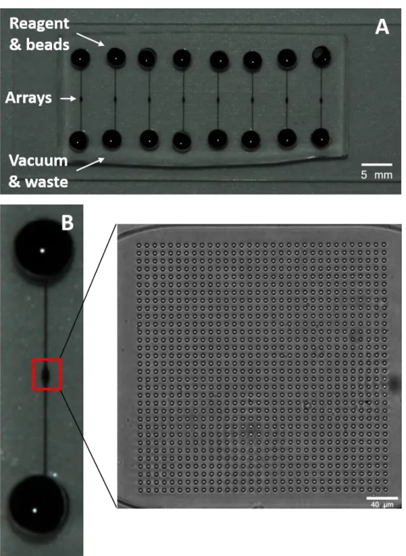
This work builds on a microfluidic device previously designed and reported on by the Ramsey group and collaborators (Figure 2.1).1,2 The device incorporated an array of antibody-coated microspheres (beads) and used multiplex sandwich immunoassays to determine the concentrations of cytokines in human saliva. Four reagent inlets/vias introduced sample, biotinylated detection antibody (dAb), a streptavidin-conjugated fluorescent complex, and wash buffer to the chip. Fluid flow from the reagent inlets was controlled by pinch valves. While the device was designed to be used in a single experiment with an automated reader,2 its
experimental parameters were developed through use of a simpler version of the chip that facilitated running many assays simultaneously. The simplified device (Figure 2.2A) featured eight single straight channels with bead arrays at their center, vias for introducing beads/reagent to the chip, and vias for applying waste/vacuum. A 1,024-microwell array and its corresponding location on one of the straight channels is shown in Figure 2.2B. With this simple design, 8 assays/chip can be run simultaneously in addition to running multiple chips as well. With the large throughput capability, the device was used to develop the immunoassay by testing different experimental conditions. This included the testing of antibody pairs for sandwich
immunoassays, the optimization of reagent concentrations and incubation times, and the lengths of wash steps between each incubation.
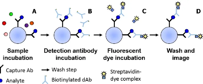
pERK1/2:ERK1/2 in human samples. The first is its utilization of the sandwich immunoassay. Figure 2.3 shows the steps of a sandwich immunoassay with the first step involving an antibody capturing a target analyte during a sample incubation period (Figure 2.3A). After a wash step, a dAb is introduced to bind to a second epitope site on any captured target analyte (Figure 2.3B). The dAb in these particular assays has been conjugated with multiple molecules of biotin. After the dAb incubation, a streptavidin-conjugated fluorescent label is introduced and incubated with the beads (Figure 2.3C). Streptavidin and biotin bind together rapidly with extremely high affinity,3 and the fluorescent label thus becomes bound to the antibody-analyte complex. Unbound streptavidin-fluorescence complex is washed away and a fluorescence image of the beads taken (Figure 2.3D). The amount of fluorescent label present corresponds directly to the amount of analyte captured.
This two-antibody feature of sandwich immunoassays can be applied for determining the phosphorylation ratio of ERK1/2. Due to the ~83-85% sequence homology of ERK1 and ERK2,4 they share many epitopes, making it possible to capture all phosphorylation states of ERK1 and ERK2 with one monoclonal capture antibody. As phosphorylation considerably changes the shape of ERK1 and ERK2,5 a monoclonal dAb that recognizes only pERK1 and pERK2 can be used to distinguish them from non-phosphorylated ERK1 and ERK2 (nERK1 and nERK2). Two assay strategies are possible based on this.
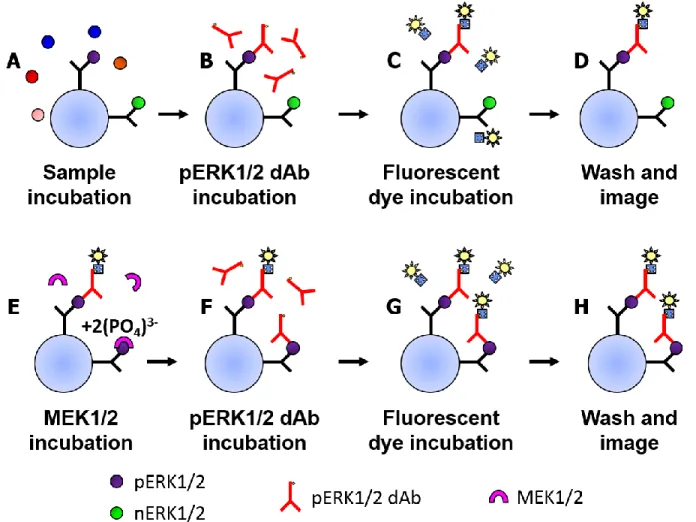
mitogen-activated protein kinase kinases 1 and 2 (MEK1/2), the enzymes responsible for phosphorylating ERK1/2 in vivo,4 are then incubated with the necessary cofactors in order to convert all captured nERK1/2 to pERK1/2 (Figure 2.4E). The pERK1/2 dAb is incubated a second time (Figure 2.4F) in tandem with the fluorescent streptavidin complex (Figure 2.4G) and the captured complex’s fluorescence is measured (Figure 2.4H). The ratio of the fluorescence from the initial pERK1/2 measurement and the second pERK1/2 measurement corresponds to the sample’s ratio of pERK1/2 to total ERK1.2 (pERK1/2:ERK1/2). An initially highly
phosphorylated sample would yield a relatively high fluorescence ratio between the two measurements. In a clinical sample, this would be seen in many cancers due to overexpression of the ERK1/2 pathway, though the extent of overexpression varies by patient, disease, and disease stage.6 A sample from a healthy patient would have a low proportion of pERK1/2 and would experience a greater degree of phosphorylation during the MEK1/2 incubation. The fluorescence from the second measurement would thus be greater than from the first.
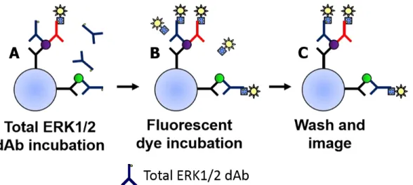
The second assay strategy for determining pERK1/2:ERK1/2 utilizes two distinct dAbs (Figure 2.5). In addition to the pERK1/2 dAb, a dAb that recognizes all phosphorylation states of ERK1/2 is used to determine the total amount of ERK1/2 captured. A standard immunoassay as in Figure 2.3 would be performed with a pERK1/2 dAb, followed by introduction of the total ERK1/2 dAb and subsequent measurement of the total ERK1/2. It is also possible to reverse the dAb incubation steps, first using the total ERK1/2 dAb and then the pERK1/2 dAb.
issue because target epitopes for many monoclonal antibodies may be poorly accessible in the native protein, requiring the protein to be unfolded with a denaturing agent like urea7 to expose the binding site. The two-dAb approach has the advantage of not requiring nERK1/2 to be in their native conformations in order for dAb recognition. The cost may also be lower since MEK1/2 is not required. A disadvantage is the need for a total ERK1/2 dAb in addition to the pERK1/2 dAb. Ideally, the total ERK1/2 dAb would be capable of binding to ERK1/2
molecules captured by the pERK1/2 capture antibody, as only one capture bead type would then be needed. The use of a total ERK1/2 dAb not capable of such binding would require at least two bead types, further complicating experimental procedures and data analysis.
While capture antibodies for sandwich immunoassays can be affixed to many surfaces, including microtiter plate wells8 and microfluidic channels,9 covalently binding antibodies to beads has several advantages over these approaches. A single coupling reaction can produce enough antibody-coated beads for months or even years of experiments, while other approaches often require a long incubation step to immobilize the capture antibody on the surface prior to sample introduction for each experiment. The use of beads from a single antibody-bead reaction for many assays improves interexperimental reproducibility as well as experimental throughput. Beads can be spatially placed within a device without the need for such steps as photoinitiated or passive antibody-surface binding, and through the use of internal encoding dyes, beads coated with different capture antibodies can be distinguished to assay numerous analytes
This chapter covers efforts in developing a microfluidic bead-based immunoassay for determining pERK2 and nERK2 using the simple array device shown in Figure 2.2. Several assay parameters including the detection fluorophore and the reagent incubation times are examined, and different capture and dAbs are also tested. The two assay strategies (single-dAb and dual-dAb) for determining pERK1/2:ERK1/2 are developed and compared in terms of their sensitivity and the signal levels they yield for various pERK2 and nERK2-containing samples. 2.2 Materials and methods
2.2.1 Materials and reagents
Dow Corning's Sylgard 184 PDMS was purchased from Ellsworth Adhesives (Germantown, WI) and was prepared according to the manufacturer's instructions at a 10:1 elastomer/cross-linker ratio. Tris-buffered saline with 0.05% Tween-20 (TBS-Tween), 1-ethyl-3-(-3-dimethylaminopropyl) carbodiimide hydrochloride (EDAC), N-hydroxysulfosuccinimide (sulfo-NHS), octyltrichlorosilane, sodium fluoride, ethylene diamine tetraacetic acid (EDTA), urea, and Triton X-100 were purchased from Sigma-Aldrich (St. Louis, MO). Sodium phosphate monobasic, 2-(N-morpholino)ethanesulfonic acid (MES), 10x phosphate-buffered saline (PBS, pH = 7.4), 10% bovine serum albumin (BSA) in PBS, sodium azide, optically clear
Tween-20 and MagPlex Luminex beads were purchased from Bio-Rad Laboratories (Hercules, CA). Non-magnetic Luminex beads were purchased from Luminex Corporation (Austin, TX). Polyethylene glycol (PEG) with an average molar mass of 10,000 g (PEG10k) was purchased from Alfa Aesar (Ward Hill, MA). MF-319 photoresist developer, KMPR 1010 photoresist, and SU-8 thinner were purchased from MicroChem (Newton, MA); the SU-8 thinner was mixed with KMPR 1010 to prepare 35% (w/w) KMPR solutions. P-type 6” crystalline Si wafers were purchased from University Wafer (Boston, MA). Streptavidin-B-phycoerythrin (SA-PE) and streptavidin-Alexa Fluor 488 (AF488) were purchased from Invitrogen (Carlsbad, CA). All aqueous solutions were prepared with deionized (DI) water from a NANOpure Diamond system (Barnstead International, Dubuque, IA).
Several different blocking buffers are used during immunoassay experiments, all of which are prepared in 1x PBS buffer. PBS-PEG contains 0.1% PEG-10k. PBS-B contains 0.1% BSA and 0.05% Tween-20. PBS-BTBL contains 1% BSA and 0.05% Tween-20. ERK buffer contains 5 mM sodium fluoride, 1 mM EDTA, 1 M urea, and 0.5% Triton X-100. A variant of ERK buffer without 1 M urea is also used in one experiment.
2.2.2 Bead-antibody coupling
nm emission) purchased from Semrock (Lake Forest, IL) was used for distinguishing between beads containing different concentrations of Luminex’s infrared-emitting dye.
Through use of the carboxyl groups covering the beads’ surfaces, antibodies and other ligands of interest can be covalently bound to the beads. Antibody linkage to the beads was done via the carbodiimide chemistry of EDAC and sulfo-NHS. EDAC is a heterobifunctional cross-linker, one end binding to the carboxyl groups on the beads, and the other binding to surface amine groups on amino acid residues in immunoglobulin-G (IgG) antibodies. Sulfo-NHS is used in conjunction with EDAC to yield a less labile chemical intermediate, which allows for a much longer bead-antibody coupling period and thus greater coupling efficiency.13
2.2.2.1 Coupling procedure for non-magnetic beads
The procedure for coupling antibodies to beads was provided by the vendor14 and is summarized here. It utilizes four buffers that are prepared prior to each bead coupling. The activation buffer is 100 mM sodium phosphate monobasic at a pH of 6.2. The coupling buffer is 50 mM MES at a pH of 5.0. Sodium hydroxide and hydrochloric acid were used to adjust buffer pH. The wash buffer is PBS + 0.05% Tween-20. The storage/blocking buffer is PBS + 0.1% (BSA) + 0.02% Tween-20 with 0.05% sodium azide as a preservative. The stock beads are at a concentration of 12.5 million beads/mL. All buffers and beads were brought to room
temperature prior to use. Region 1 beads were used with the control antibody and region 50 beads were used with the VEGF capture antibody.
resuspended by vortexing them for 30 s at 3000 rpm, then pelleted. The supernatant was removed and replaced with 80 µL of activation buffer. 10 μL of 50 mg/mL sulfo-NHS and 10 μL of 50 mg/mL EDAC (both prepared in activation buffer) were added and the beads were vortexed at 3000 rpm for several seconds. The beads were activated by placing them on a plate shaker (MS1 S7, Fisher Scientific) at 1000 rpm for 20 min at room temperature. The activated beads were pelleted and the supernatant was replaced with 250 µL of coupling buffer. The beads were resuspended and then pelleted. The supernatant was removed and replaced with 250 µL of coupling buffer. 16 µg capture antibody (prepared in PBS) was added and the total volume of the mixture was brought to 500 µL with coupling buffer. The bead tube was covered with foil, gently vortexed, and placed on a 25 rpm rotator (H5500; Labnet International Inc., Edison, NJ) for 2 h at room temperature to couple the beads to the antibodies.
Coupled beads were pelleted and resuspended in 500 µL storage/wash buffer. They were then pelleted, resuspended in 1 mL storage/wash buffer, and this step was repeated once more. The beads were finally resuspended in 250 µL storage/wash buffer and stored at 4 ºC until use. 2.2.2.2 Coupling procedure for magnetic beads
The procedure for coupling antibodies to beads was provided by Bio-Rad.15 The buffers used for coupling antibodies to magnetic beads are the same as those for the non-magnetic beads, except the coupling buffer is PBS at a pH of 7.4. The stock beads are at a concentration of 12.5 million beads/mL. All buffers and beads were brought to room temperature prior to use.
vortexing at 3000 rpm for 30 s and then pelleted with the magnet. With the bead tube still on the magnet, the wash buffer was removed and replaced with 80 μL of activation buffer, then the beads were vortexed at 3000 rpm for 30 s. 10 μL of 50 mg/mL sulfo-NHS and 10 μL of 50 mg/mL EDAC (both prepared in activation buffer) were added and the beads were vortexed at 3000 rpm for several seconds. The beads were then placed on a plate shaker (MS1 S7, Fisher Scientific) at 1000 rpm for 20 min at room temperature. 150 μL of coupling buffer was added and the beads were pelleted on the magnet. The supernatant liquid was removed and then 150 μL of coupling buffer was added. The beads were resuspended by vortexing at 3000 rpm and pelleted again. The supernatant was removed and replaced with 100 μL of coupling buffer. 9 µg of capture antibody (prepared in PBS) was added and the total volume of the solution was
brought to 500 μL with coupling buffer. The beads were vortexed and then incubated on a 25 rpm rotator for 2 h at room temperature to couple them to the antibody.
The coupled beads were pelleted from solution and the supernatant was removed. 250 μL of storage/blocking buffer was added and the beads were vortexed at 1500 rpm for 15 s. The beads were pelleted, the supernatant was removed, and 500 μL of storage/blocking buffer was added. The beads were vortexed for 20 s at 1500 rpm and pelleted again. The supernatant was removed and 100 μL storage/blocking buffer was added. The antibody-coupled beads were stored at 4 ºC when not in use.
2.2.3 Fabrication of master molds and assay chips
The chips used to determine appropriate antibodies/incubation buffers/wash buffers consisted of eight linear channels with a microarray centered in each (Figure 2.2). With the 8 channels, replicate measurement can be made simultaneously. The linear channel is
is spaced 5.6 mm apart. Once fabricated, a 3-mm hole is made at each end of the channel for sample/reagent delivery and waste/vacuum. The chips are filled with a blocking buffer (varied by experiment) by pipetting buffer into the reagent inlet and pulling vacuum on the opposite end. The bead array consists of 1,024 circular wells with 11 μm center-to-center spacing; as the beads have an average diameter of 6.5 μm, the 11-micron well spacing corresponds to slightly less than two bead diameters. This spacing was previously found to prevent the problem of fluorescence overlap between the beads when imaging. The wells are approximately 5.2 μm in lateral diameter with a depth of approximately 5 μm.
Designs for the straight-channel chips were created in TurboCAD Professional 14 drafting software (IMSI/Design, Novato, CA) and the corresponding photolithography mask received from Infinite Graphics (Minneapolis, MN). This mask was divided into two halves, one with the microwell array features and the other with the channels.
2.2.3.1 Fabrication of silicon masters
in the DRIE and the etched feature sizes were determined with profilometry (P-15; KLA-Tencor, San Jose, CA).
The procedure to fabricate the channel layer was the same as that used for the microwell arrays except for the following details. 55% (w/w) KMPR was used instead of 35% to produce a 9-µm-thick layer in order to protect the microwell array. Exposure of the channel layer features required topside alignment of the mask’s and mold’s fiducials in the mask aligner. Channels were etched to a depth of approximately 20 µm. The completed master mold was silanized in a vacuum desiccator for 1 h with 500 µL of octyltrichlorosilane.
2.2.3.2 PDMS chip fabrication
To make chips, 10:1 PDMS was mixed and degassed. Approximately 13 g of PDMS were poured onto the center of the silicon master and spun in a two-step process at 150 rpm for 10 s followed by 200 rpm for 30 s. The coated wafer was degassed under vacuum then cured on a hot plate at 150 °C for 3 min. Two additional PDMS layers were cast and cured in the same manner, although air bubbles were removed with a nitrogen gun or via the spin-coating process, not with vacuum, as vacuum could delaminate the first PDMS layer. The PDMS was peeled from the wafer and laid upon glass cleaned with 5% Contrad and deionized water. Reagent/bead and waste/vacuum vias were created in the channels with a 3 mm biopsy punch (Sklar
stabilize the PDMS.16
2.2.4 Loading beads into microarrays
To load antibody-coupled beads into the arrays, the chips are first filled with a blocking buffer consisting of PBS + 1% BSA + 0.05% Tween-20 (PBS-BTBL). A bead slurry containing a 1:1 mix of both target and control beads was then pipetted into the sample inlet and vacuum applied on the outlet to pull the beads into the channel (Figure 2.6A). As the beads flow into the microarray chamber, the PDMS above the array is pressed down to force beads into the wells (Figure 2.6B). As the diameter of an unloaded microwell is smaller than the bead diameter, the microwell stretches to accommodate the bead, which is held in place by the elastic force of the PDMS attempting to relax to its native state (Figure 2.6C). The extent of the microarray’s loading is monitored using an epifluorescent microscope, and the loading process stopped when approximately 90%+ of the microwells are loaded (Figure 2.6D). Remaining bead slurry is removed from the inlet and the chips are filled with fresh PBS-BTBL (Figure 2.6E). The inlet/outlet are sealed with PCR tape and stored at 4 ºC for at least 24 h prior to use (Figure 2.6F).