Sharif University of Technology
Scientia IranicaTransactions A: Civil Engineering www.scientiairanica.com
Numerical characterization of anisotropic damage
evolution in iron based materials
A.R. Khaloo
a;, M.R. Javanmardi
band H. Azizsoltani
aa. Department of Civil Engineering, Sharif University of Technology, Tehran, P.O. Box 11155-9313, Iran. b. Department of Civil Engineering, Shiraz University, Shiraz, Iran.
Received 2 February 2013; received in revised form 28 April 2013; accepted 11 June 2013
KEYWORDS Damage plastic constitutive model; Anisotropic damage; Modied forward Euler integration.
Abstract. A damage plastic constitutive model for metals is proposed in this paper. An anisotropic damage tensor and a damage surface are adopted to describe the degradation of the mechanical properties of metals. The model is developed within the thermodynamic framework and creates an anisotropic damage plastic model with the ability to describe the plastic and damage behavior of iron based materials. According to the principle of strain energy equivalence between the undamaged and damaged materials, the linear elastic constitutive equations for the damaged material expressed a stiness tensor in the damaged conguration. The damaged material is modeled using the constitutive laws of the undamaged material, in which the stresses in the undamaged conguration are replaced by the stresses in the damaged conguration. To simulate the onset of plastic deformation and damage, yield and damage surfaces are applied and, in accordance with the normality rule, evolution laws for the damage variables are achieved to complete the proposed damage plastic model. Implementation of the model in the form of a practical method, based on the forward Euler integration scheme (modied forward Euler integration with error control) is discussed. Finally, the constitutive response is compared with some experimental results and classical plasticity results for validating the capability of the proposed model. Good agreement between the experimental results and the model is obtained.
c
2014 Sharif University of Technology. All rights reserved.
1. Introduction
In recent decades, plasticity theories have been de-veloped for materials such as metals and concrete. Plasticity theories have evident advantages over elastic approaches in the modeling hardening and softening characteristics of materials. However, they do not clearly incorporate the damage process due to microde-fects (microcracks and microvoids), such as stiness degradation.
*. Corresponding author. Tel.: +98 21 66164211; Fax: +98 21 66019799
E-mail addresses: [email protected] (A.R. Khaloo); [email protected] (M.R. Javanmardi); [email protected] (H. Azizsoltani)
Although classical fracture mechanics models were originally developed for demonstrating material degradations, much eort is still being devoted towards developing new fracture mechanics models. In spite of some successful applications of fracture mechanics, for practical applications, it is dicult to dene the location and geometry of the microcracks accurately before they are formed.
Damage models were produced to create an al-ternative approach towards modeling material degra-dation based on the thermodynamics of an irreversible process. In damage plasticity models, material nonlin-earity may be associated with two dierent material mechanical processes: plasticity (dislocations along crystal slip planes) and damage mechanics (microvoids, microcracks). These two degradation phenomena are
described by the theories of plasticity and continuum damage mechanics. Therefore, a model that accounts for both material deterioration and the dislocations along slip planes is needed. This can be achieved by using a plastic surface and a damage surface.
The concept of damage models was rst proposed by Kachanov [1] who considered the isotropic damage model of a one dimensional (scalar) variable, dened as the eective surface density of microdefects per unit volume [2,3]. This phenomenological damage model was introduced upon the assumption that microdefects start from the very beginning of loading, with two stages in the fracturing process. Firstly, the regular development stage of microdefects and, secondly, the accelerated stage of fracturing. Therefore, it notes that \in the presence of an aggressive environment, microdefecting grows, mostly, from the surface of the body." Accordingly, they dene the scalar damage variable (eective surface density of microdefects per unit volume) as the ratio of damage surface area to total surface area. This concept is established upon considering the equivalence between the imaginary un-damaged conguration of a body and the real un-damaged conguration. Rabotnov [4] proposed the concept of eective stress in continuum damage mechanics. The scalar damage variable, rst proposed by Kachanov, is the simplest case of continuum damage models.
Many researchers used this scalar measure to adequately solve many mechanics problems [4-6]. How-ever, in actuality, it is shown that all materials have anisotropic damage characteristics and, in the most general case of anisotropy, the description of damage needs to be embodied in an eight-order tensor, while the principle of strain equivalence allows the use of fourth-order tensors [7].
Careful consideration of isotropic models leads us to the fact that these models have less strength in comparison to anisotropic damage models. Moreover, in cases of triaxial loading, the dierences between isotropic (scalar) models and anisotropic (tensorial) models are much more noticeable. On the other hand, for better characterization of the material damage behavior, such as dierent microcracks in diverse di-rections, anisotropic damage should be characterized. In general, a fourth order tensor should be used as a damage state variable in order to capture the true eect of microcracks [6]. Nevertheless, anisotropic damage is complex. Its combination with plasticity and its appli-cation to structural analysis are non-straightforward [8-11] and, therefore, it has been avoided by many authors.
In this work, a coupled anisotropic damage and plasticity constitutive model that can be used to predict metal behavior is formulated within the basic framework of thermodynamics.
In this model, using the second law of
thermody-namics, the internal energy of material (current), which is expressed through Helmholtz free energy, is dened. Then, using Helmholtz free energy, useable variables to show the plastic and damage growth of material are introduced. Finally, in the framework of ther-modynamics of irreversible processes, thermodynamic conjugate forces are established via state equations using state potential.
In this work, computational aspects concerning numerical implementation and the algorithmic con-sistent tangent modulus for the constitutive model are presented. Therefore, two nonlinear problems are considered, and the results obtained by the proposed model are compared with corresponding experimental results of specimens to validate and demonstrate the capability of the proposed model.
2. Anisotropic damage
In classical plasticity theory, the growth and coales-cence of microdefects in material due to an increase in deformations were not considered. By using an anisotropic damage model, it is attempted to regard the growth and coalescence of microdefects, besides plastic deformation, in the material. In this article, two con-gurations; undamaged and damaged, are considered. The former are designated by a superimposed dash and the latter are designated without a superimposed dash. Throughout this work, superscript T indicates the transpose of the tensor as dened by AT
ijkl= Aklij,
superscript -1 indicates the inverse of the tensor as dened by A 1
ijklAmnkl = imjn, and superscript T
indicates the transpose of the inverse of the tensor (ij
is Kronecker delta).
Cordebois and Sidoro [12] proposed the stress relationship between undamaged and damaged congu-rations. That is, the damaged material is formulated by using the constitutive laws of the undamaged material, in which the Cauchy stress tensor in the damaged conguration () is replaced by the stress tensor in the undamaged conguration () [12-16]:
ij= Mijklkl; (1)
where Mijkl is the fourth order damage eect tensor.
In order to create a symmetrical stress tensor in the damaged conguration, many dierent expressions for Mijkl have been proposed. In this work, the
following expression for Mijkl, proposed by Cordebois
and Sidoro [12], is used:
Mijkl= 12(ilwkj+ wilkj) : (2)
In this relationship, ij is Kronecker delta and wij is
dened as follows:
where 'ij is the second order damage tensor. The
second order damage tensor is dened as follows [2,13-14,17-20]:
'ij=
p
didj; (4a)
di=A d i
Ai(no sum on i); (4b)
where di is the microdamage density vector, and
dened in Eq. (4b). Ad
i(i = 1; 2; 3) is the total area
of the defects and Ai is the total area of the surface,
whose unit normal is ni.
The explicit matrix representation for the fourth order damage tensor (Mijkl) is mentioned in [19].
One can write the linear elastic constitutive equations for the damaged material according to the principle of elastic strain energy equivalence between the undamaged and damaged material [12,18]:
1
2ij"eij =12ij"eij: (5)
One of the main hypotheses of the small strain theory of plasticity is decomposition of the total strain tensor, "ij, into the sum of an elastic strain tensor (reversible
part), "e
ij, and a plastic strain tensor (irreversible part),
"pij. Therefore, the total strain tensor, "ij, in both
congurations are dened as follows:
"ij = "eij+ "pij; (6a)
"ij = "eij+ "pij: (6b)
The relationships between stress and elastic strain tensors in damaged and undamaged congurations are: ij = Eijkl"ekl; (7a)
ij = Eijkl"ekl; (7b)
where Eijkl and Eijkl are, respectively, the stiness
tensors in damaged and undamaged congurations. Substituting Eqs. (7a) and (7b) in Eq. (5) and using Eq. (1) gives:
Eijkl= Mijmn1 EmnpqMpqklT: (8)
Substituting Eqs. (7a) and (7b) in Eq. (1) and using Eq. (8) leads to the elastic strain tensor relationship in damaged and undamaged congurations.
"e
ij = MijklT"ekl: (9)
3. Thermodynamic framework
To explain the elastic, plastic and damage behavior of material, a thermodynamic framework can be used [21-26]. In this work, the deformations in the material are divided into elastic, plastic and damage parts. In this division, elastic deformation is a reversible process that does not result in an entropy increase in the system, while plastic and damage deformations are irreversible processes that lead to entropy production in the system.
Clausius-Duhem inequality is the result of substi-tuting the content of the second law of thermodynamics in the notation of continuum mechanics; this inequality means the production of entropy within a system in an irreversible process [21], and can be expressed as follows:
ij_"ij _ 0; (10)
in this equation, is Helmholtz free energy, is material density, ij is stress tensor and _"ij is the rate
of strain tensor.
In this work, the Helmholtz free energy function is dened based on four variables:
1. Elastic strain tensor ("e ij);
2. Equivalent plastic strain variables in damaged conguration ("ep), which is used to characterize
isotropic hardening accumulated plastic strain;
3. Second order damage tensor ('ij);
4. Equivalent damage variable ('eq) used to
char-acterize accumulated inelastic-damage strain, and which represents the creation and dissemination of microcracks in materials.
= "e
ij; "ep; 'ij; 'eq: (11)
Chaboche [27] expressed the thermodynamic conjugate forces of these variables as follows:
Yij= @'@
ij; (12a)
K = @
@'eq; (12b)
C = @"@ ep: (12c) If the mechanical ux vector is dened as J, and vector X is considered to be thermodynamic conjugated forces expressed as follows:
J = _"pij; _'ij; _"ep; _'eq T; (13a)
The production rate of entropy is expressed as [28,29]: ij_"ij _ = X:J 0: (14)
With assuming the components of J vector, (Jk) are
dened, one to one, as a function of X vector (Xk),
and the existence of potential functions, FP and g, are
proved as follows [29,30]: Fp= Fp
ij; C; _"pij; _"ep
; (15)
g = g (Yij; K; _'ij; _'eq) : (16)
Now, components of J vector (Jk) are expressed as
follows [29,30]: _"pij= _p@Fp
@ij; (17a)
_'ij = _d@Y@g
ij; (17b)
_"ep= _p@Fp
@C ; (17c)
_'eq = _d @g
@K; (17d)
where _p and _d are obtained by plastic and damage
consistency.
4. Helmholtz free energy function
The Helmholtz free energy function is a part of the internal energy of a system that can do work under a constant temperature [21]. In this work, the Helmholtz free energy function is divided into elastic, plastic and damage parts. These three parts are expressed as follows:
e= 1
2ij"eij; (18)
p= Q"ep+ 1
Bce Bc"
ep
; (19)
d('eq) = 1
2Kd('eq)2: (20) In these relationships, Q, Bc and Kd are material
constants that are obtained from a uniaxial test. Using Eqs. (12a), (12b), (12c), and the Helmholtz free energy function expressed in Eqs. (18), (19) and (20), thermodynamic conjugate forces can be obtained as follows:
Yrs = ij@M@'ijmn rs E
1
mnpqMpqklkl; (21)
C = @"@ ep = Q1 e Bc"ep
; (22)
K = @'@ eq = Kd'eq; (23)
where Yrs, C and K are, respectively, the
thermody-namic conjugate forces of 'rs, "epand 'eq.
5. Damage plastic model
To explain the behavior of iron based materials, such as high strength steel and aluminum, in triaxial loading, an appropriate constitutive model based on two yield surfaces is applied. One of the yield surfaces shows the plastic onset, and the other shows the damage onset of material.
5.1. Plastic yield surface
In order to describe the hydrostatic stress dependency of the plastic material, a yield surface based on I1
J2 J3, taking into account isotropic nonlinear work
hardening, is used.
Burzynski [31,32] gave the rst consistent energy-based formulation of a yield surface, accounting for the rst invariant of the stress tensor, in 1928. Moreover, Vadillo et al. [33] presented a numerical approach based on the Burzynski yield condition, while Pecherski et al. [34] gave the extension of the energy-based Burzyn-ski yield condition accounting for the third invariant of the stress deviator. The yield surface derived from experimental results on aluminum and high strength steels was proposed by Spitzig et al. [35,36] and Spitzig and Richmond [37], and is expressed as follows:
aI1+
p J2+ b3
p
J3= C("ep): (24)
In this equation, I1 = ii is the rst invariant of the
stress tensor, J2 = SijSij=2 is the second invariant
of the deviatoric stress tensor, J3 = SijSjkSkl=3 is
the third invariant of the deviatoric stress tensor, and
Sij = ij kkij=3 is the deviatoric stress tensor.
All variables are in undamaged conguration. a is a coecient relating the hydrostatic stress state, b describes the deviation of the yield condition from the von Mises circle in the deviatoric stress plane, "ep =
t
R
0 _"
epdt is equivalent plastic strain in the undamaged
conguration, and C is the hardening parameter, which can be expressed as follows [16]:
C("ep)= C(" ep)
1 'eq: (25)
Experimental data from tests on steel and aluminum alloys by Spitzig et al. [35,36] have shown that the ratio of = a= C is constant, = b= C is assumed constant, and the yield function is written in general form as:
f (; "ep) =
p J2
1 I1 3
p J3
The rate of plastic strain tensor in strain space is nor-mal to plastic potential function (FP) that is dened
by Eq. (17a). This relationship in the undamaged conguration is expressed as follows:
_"p
ij = _p@F p
@ij: (27)
In elasto-plastic deformed and damaged metals, irre-versible volumetric strains are essentially caused by material damage and volumetric plastic strains are insignicant [35,36]. Thus, the non associated plastic potential function is expressed as:
Fp=pJ
2: (28)
The derivative of plastic potential function (Fp), with
respect to ij, leads to:
@Fp
@ij =
Sij
2pJ2
: (29)
Since material in a plastic state should always be on a plastic yield surface ( _f = 0), plastic consistency is expressed as follows [38]:
f 0; _p 0; _pf = 0; _p_f = 0: (30)
The time derivative of plastic yield surface function (f) is:
_f = @f @ij _ij+
@f
@"ep_"ep= 0; (31)
where:
Eqs. (32) and (33) are shown in Box I.
Evolution of the isotropic hardening function (@ C
@ "ep) is dened by the following exponential law [16]:
@ C
@"ep = Bc Q C
: (34)
If eective stress in the undamaged conguration is assumed to be equal to the yield stress of material in uniaxial tests, this stress in the undamaged congura-tion is dened as:
e=
p 3 J2
1 I1 3
p J3+
+ p32 3
p 3 J2
: (35) Assuming that the rate of eective plastic work per unit volume and rate of plastic work per unit volume are equal in the undamaged conguration, gives:
dwp = e_"ep= ij_"pij: (36)
By substituting Eqs. (27) and (35) in Eq. (36), the rate of equivalent plastic strain in the undamaged conguration is dened as follows:
_"ep=1 I1
3
p J3+
+ p32 3
p 3 J2
p 3 J2
_p ij@F
p
@ij; (37a)
_p= 1
h@@fij
Eijkl_"kl: (37b)
The elastoplastic tangent operator in the undamaged conguration that is not principal symmetric, due to the assumption of a non associated plastic ow rule, it can be expressed as follows:
_ij= Dijkl_"kl; (38a)
Dijkl= Eijkl h1Eijrs@F p
@rs
@f @mn
Emnkl; (38b)
where h is equal to: h = @f@
ij
Eijkl@F
p
@kl +
@f @ C
@ C @"ep
1 I1 3
p J3+
+ betap32 3
p 3 J2
p 3 J2
ij@F p
@ij(39):
@f @ij =
Sij
1 I1 3
p J3 2pJ2 +
ij+3 J2=3 3
SikSkj 23J2ij p J2
1 I1 3
p J3
2 ; (32)
@f @"ep =
@f @ C
@ C
@"ep = Bc Q C
: (33)
5.2. Damage surface
To establish the onset and growth of damage in iron based materials, the damage surface proposed by Chow and Wang [18] can be used:
g = r
1
2YijLijklYkl (K0+ K) : (40) In this equation, g is the damage surface, Yij is the
thermodynamic conjugate force of 'ij, Lijkl= (ikjl+
iljk)=2 is a symmetric fourth order tensor [38-41],
K0 is the material constant that is described as the
initial damage, and K is the thermodynamic conjugate force of 'eq. Writing the consistency condition for the
damage surface ( _g = 0) gives [16]: _g = @Y@g
mn _Ymn+
@g @K
@K
@'eq _'eq= 0; (41)
where: @g @Yij =
LijklYkl
2q1
2YmnLmnpqYpq
; (42)
@g
@K = 1; (43)
@K
@'eq = Kd: (44)
The time derivation of Yij gives:
_Yij = @Y@ij kl_kl+
@Yij
@'kl _'kl: (45)
And the rate of equivalent damage is dened as [9,16]: _'eq =p_'
ij _'ij: (46)
Substituting Eq. (17b) in Eq. (46) gives: _'eq = _
d
s @g @Yij
@g
@Yij: (47)
Substituting Eqs. (47) and (45) in Eq. (41) leads to an incremental relationship between the second order damage tensor and the stress tensor [16]:
_'ij = Bijkl1Aklmn_mn; (48)
where:
Bijkl= kilj @g @Ymn
@Ymn
@'kl
@g @Yij
@K @'eq@K@g
; (49)
and: Aklmn=
@g @Yij
@Yij
@mn
@g @Ykl
@K @'eq@K@g
; (50)
= r
LmnklYklLmnpqYpq
2YrsLrstuYtu : (51)
The rate of stress tensor in the damage conguration obtained by the time derivative of Eq. (1) is:
_ij = @M@'ijkl
mn _'mn+ Mijkl_kl: (52)
Substituting Eq. (48) in Eq. (52) leads to:
_ij = Pijkl1 _kl; (53)
where:
Pijkl= Mijkl+@M@'ijpq rs B
1
rsmnAmnklpq: (54)
For mapping the elastoplastic tangent operator in the undamaged conguration to the damaged congura-tion, by substituting Eq. (53) into Eq. (38a), the elastoplastic damaged tangent operator is dened as follows:
Cijklepd = P 1
ijmnDmnkl: (55)
The elastoplastic damage tangent operator (Cijklepd) represents the relationship between the rate of stress in the damaged conguration and rate of strain in the undamaged conguration.
_ij = Cijklepd_"kl: (56)
The elastoplastic damage tangent operator is used in the next section in order to obtain a relationship between the rate of stress in the damaged conguration and the rate of strain in the undamaged conguration (Newton Raphson iterations).
6. Finite element simulation
In the nite element method, the Newton Raphson algorithm is mainly suitable for the solution of the nonlinear incremental equations. When a good initial guess of the solution is not available, this method results in divergence. To avoid divergence, the load must be applied in incremental form. Within each load increment, the procedure should be solved by the Newton Raphson algorithm. After the solution corre-sponding to the previous load increment has converged, the next load increment is applied.
The tangent stiness matrix is written for each element using the incremental elastoplastic damage
stress strain law expressed in previous sections, as-sembled into the global matrix and then solved for increments in nodal displacements in the undamaged conguration (u). From the denition of the strain displacement matrix, the incremental strains in the undamaged conguration can be obtained as follows:
" = Bu: (57)
The well known discrete symmetric gradient operator (or strain displacement matrix) relating the increments of strain and displacement can be written as:
B =Num NodeX
i=1 2 6 6 6 6 6 6 6 6 6 6 6 6 6 6 6 6 6 4 @Ni
@x 0 0
0 @Ni
@y 0
0 0 @Ni
@z @Ni
@y @N@xi 0
0 @Ni
@z @N@yi @Ni
@z 0 @N@xi
3 7 7 7 7 7 7 7 7 7 7 7 7 7 7 7 7 7 5 ; (58)
where Ni is the standard shape function of each node
in 3D elements. By computing the corresponding stress increments in the undamaged conguration (), the new stress state is obtained (trial = prev + ).
The state determination calculations must be used for each Gauss point, because, at each Gauss point, it is required to know whether or not the stress has reached the yield surface or the damage surface.
If the trial stress is not outside the plastic surface and the damage surface, the step is elastic and the assumption is correct. However, if the trial stress is outside the plastic surface or the damage surface, the intersection point for these must be calculated. If the trial stress is outside both the plastic and damage surfaces, two intersections must be calculated, and the lower one will be considered. The remaining portion of the trial stress that does not lie within the elastic domain, must be eliminated eciently in some way, because, at all times, one must also make sure that the computed stresses do not drift away from the yield surface or damage surface.
The incremental constitutive equations are known as dierential equations. The computational pro-cedures are established upon numerically integrated dierential equations, using methods such as the Euler method. Many researchers proposed several dierent explicit and implicit methods for numerical solution of these dierential equations. In this work, a useful method proposed by M. Asghar Bhatti [42], based on the forward Euler integration, which introduces an automatic step size rule based on predictable error in
the solution (modied forward Euler integration with error control), is used.
In general, there are two basic categories of step-by-step integration methods, i.e. explicit meth-ods (forward Euler integration) and implicit methmeth-ods (backward Euler integration). A method is explicit if the equation of motion of the current time step (i+1) is not used in determining the current step displacement (i+1), while it is implicit if the current time step (i+1) is used in computing the current step displacement (i + 1).
The advantage of explicit methods is that it is not necessary to solve a system of equations, or to use iterative procedures in each time step. Hence, far less computational eort is needed per time step. This also leads to an easy implementation of explicit methods. Conditional stability is the major disadvantage of explicit methods. Consequently, a very small time step and, thus, a very large number of time steps may be needed in a time history analysis.
In implicit algorithms, nonlinear algebraic equa-tions must be solved using the Newton Raphson scheme to advance the solution. For complicated yield functions, it may not even be possible to get an analytical expression for some derivatives needed in the Newton Raphson algorithm. Furthermore, numerical experiments suggest that with reasonable error control, the explicit method is fairly eective [42,43]. Modied forward Euler integration with error control introduce an automatic step size rule based on estimated error in the solution. The step size is denoted by T and the total interval denoted by 0 T 1, with T = 0 representing the current known state and T = 1 the nal unknown state. Initially, the step size is set to T = 1. Thus, by using the known values at the current state, the solution at the nal step is achived. An initial estimate for the new state is then obtained and the second nal estimate is computed. The dierence between the stress at the two points is used as an indicator of the local error in stress. By looking at the normalized value of this error, a decision is made whether to reduce the step size or accept the step results [42].
Since the elastic, plastic and damage evolution problem is of a strain driven nature, the integration process is split into an elastic predictor and plastic and damage return mapping, to restore plastic and damage consistency, as established in Table 1 with Eqs. (59-61).
According to the concept of operator split [44], Eq. (56) can be decomposed into elastic, plastic and damage parts, leading to the corresponding numerical algorithm, including elastic-predictor, plastic-corrector and damage-corrector steps.
It is noted that during the elastic predictor and the plastic corrector steps, the damage variables are
Table 1. Elastic predictor, plastic and damage corrector.
Elastic predictor Eq. (59) Plastic corrector Eq. (60) Damage corrector Eq. (61)
_" = B _u _" = 0 _" = 0
_"p= 0 _"p= _p @Fp
@ _"p= 0
_"ep= 0 _"ep= 1
e_p : @F p
@ _"ep= 0
_ = E : _" _ = E : _"p _ = 0
_ = P 1E : _" _ is obtained from Eq. (61) = P 1: _
_' = 0 _' = 0 _' = B 1: A : _
_'eq= 0 _'eq= 0 _'eq=p_' : _'
not changed. So, Eqs. (59) and (60) are decoupled with the damage part (Eq. (61)), constituting a usual elastoplastic problem in the undamaged stress space.
At the moment when is updated in the elastic predictor and plastic corrector steps, the damage vari-ables ( _' and _'eq) are updated in the damage corrector.
The stress in damaged conguration () is obtained from Eq. (53) that is coupled with the damage. It is notable that the consistent tangent stiness is used to speed up the rate of convergence of the Newton Raphson method.
7. Application
In order to test the applicability of the proposed constitutive model in the previous sections, and eval-uate their eectiveness, two nonlinear problems are presented in this section. As a means of validat-ing, the software is produced for performing these analyses, and the obtained results are compared with the results cited in the literature. The solution is checked for mesh-dependency and, thus, a ne mesh, with considerable numerical eort, has been applied to the model for predicting the damage propagation. Furthermore, the results obtained from the presented constitutive model are compared with the results from Abaqus software with classical plasticity (von-Mises) and isotropic damage plasticity (ductile damage in Abaqus software).
Numerical tests were conducted by means of displacement control to apply the loads in order to predict hardening and softening in specimens.
7.1. Cylindrical notched bar
This specimen is a cylindrical bar with nominal diam-eter of 18 mm, height of 40 mm and a notch with a 4 mm radius. Figure 1 shows the geometry of the steel cylindrical notched bar; all dimensions are in millimeters. Numerical simulation on this specimen was done by Souza Neto et al. [43], with isotropic Lemaitre's coupled plasticity damage model [43,45,46]. Due to symmetry conditions, only one eighth of the tension specimen is considered in the nite element simulation. A spatially non-uniform nite element mesh, composed of 1216 higher order (27 nodes) 3D
Figure 1. Cylindrical notched bar.
Figure 2. Non uniform nite element mesh of cylindrical notched bar.
isoparametric elements, has been used in order to illustrate the stress and damage in the necking zone properly (see Figure 2). Table 2 presents the material parameters in nite element simulation.
Table 2. Material parameters considered in the simulation of tensile cylindrical notched bar.
Property Value
Initial Young's modulus, E (GPa) 210
Poisson's ratio, 0.3
Initial yield strength, y(MPa) 620
Initial isotropic hardening Cinitial (MPa) 174.2
Material constant in yield surface (MPa 1) 1:87 10 6
Material constant in yield surface (MPa 1) 1:3 10 5
Initial damage surface K0 (MPa) 0.22
Material constant in damage part of Helmholtz free energy function Kd(MPa) 15.5
Material constant in plastic part of Helmholtz free energy function Q (MPa) 3300 Material constant in plastic part of Helmholtz free energy function Bc (MPa) 0.4 Q are cited in the literature and others are obtained
by using an inverse identication procedure. There-fore, only rst estimates of the material parameters in Eq. (26) are obtained from the equivalent stress-equivalent plastic strain curves. Afterwards, nite element simulations of the smooth tension tests have been performed, which leads to the nal material parameters for the work-hardening function Eq. (26) using an inverse identication procedure.
The evolution of the damage variable obtained in the numerical simulation is shown in the contour plots in Figure 3(a)-(d). It can be seen that during
the early stages of the loading process, maximum damage is detected near the edge of the notch. As the specimen is gradually pulled, the maximum damage zone moves slowly towards the middle of the specimen, and localizes there. At the end stage, damage is particularly localized around the centre.
In Figure 4, the contour distribution of von Mises stress is shown at the end of loading.
Furthermore, good correlation of the reaction forces against edge displacement obtained numerically by Souza Neto et al. [43] and predicted by nite element simulation, based on the presented model, can be seen
Figure 3. Damage contour plots in cylindrical notched bar: (a) At u = 0:05; (b) at u = 0:1; (c) at u = 0:25; and (d) at the end of loading.
Figure 4. Von Mises stress of the cylindrical notched bar.
Figure 5. Edge displacement against reaction force of the cylindrical notched bar.
in Figure 5. This prediction is in accordance with experimental observations by Hancock and Macken-zie [47], and Cescotto and Zhu [48], which show that for specic notched specimen congurations, damage initiates at the edge of the notch, and by increase in loading extends radially towards the center of the notch.
Figure 5 also shows that the presented model anticipates the force-displacement better than classical plasticity with isotropic damage, which is given by Abaqus software.
The reason for the rapid growth of damage at the centre of the specimen is the fact that damage growth in ductile metals is strongly dependent on the stress triaxiality ratio, which is highest at the centre of the specimen.
7.2. Flat shear specimen
The specimen is a 3.19 mm thick aluminum alloy plate, from which shear, pre notched specimens were
Figure 6. Flat shear specimen.
Figure 7. Non uniform nite element mesh of at shear specimen.
machined. The specimen was tested in a screw driven machine, INSTRON3369, by Brunig [49]. Figure 6 shows the geometry of the at shear specimen, and all dimensions are in millimeters.
Machining a circular channel of 4 mm diameter in the middle of the shear specimens is necessary in order to achieve a localized shear area where triaxiality is ideally zero.
For numerical simulation of the specimen, a spatially non-uniform nite element mesh, composed of 1288 higher order (27 nodes) 3D isoparametric elements, has been chosen (see Figure 7). Material parameters are presented in Table 3.
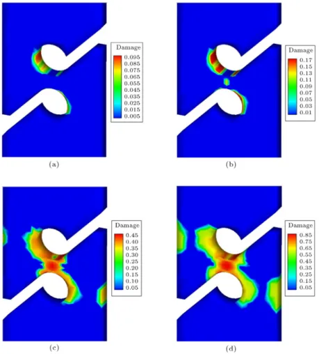
Figure 8(a)-(d) demonstrates the evolution of the equivalent damage variable eld computed in nite element simulation in contour plots.
Damage occurrence is at u=l = 2:2% and, in this loading stage, maximum damage is detected near the circular channels. With gradual loading, damage initiates in the circles, and later reaches the area between the circles in the middle of the specimen. At the nal stages of loading, damage expands in a diagonal direction, up to failure.
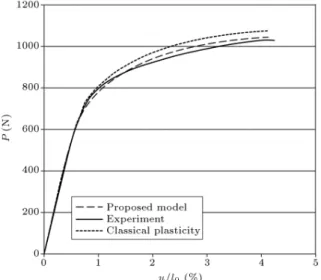
Figure 9 demonstrates Von Mises contour dis-tribution at the end of loading. Figure 10 shows the comparison between the experimental [49] and
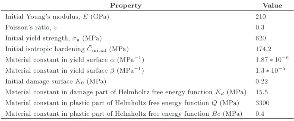
Table 3. Material parameters considered in the simulation of at shear specimen.
Property Value
Initial Young's modulus, E (GPa) 65
Poisson's ratio, 0.3
Initial yield strength, y(MPa) 340
Initial isotropic hardening Cinitial (MPa) 189.7
Material constant in yield surface (MPa 1) 5*10 5
Material constant in yield surface (MPa 1) 2.1*10 6
Initial damage surface K0 (MPa) 1
Material constant in damage part of Helmholtz free energy function Kd(MPa) 24
Material constant in plastic part of Helmholtz free energy function Q (MPa) 350 Material constant in plastic part of Helmholtz free energy function Bc (MPa) 24
Figure 8. Damage contour plots in at shear specimen: (a) At u=l = 2:8%; (b) at u=l = 3:5%; (c) at u=l = 3:8%; and (d) at the end of loading.
predicted results by numerical simulation. In this gure, the external force is plotted against strain in the critical area (12.5 centimeters from the middle of the specimen). It can be seen that the present model ac-curately describes the experimental results. Figure 10 also shows that the presented model anticipates the force-displacement better than classical plasticity with isotropic damage given by Abaqus software.
8. Conclusion
This paper presents a new anisotropic damage con-stitutive model for iron base materials based on a thermodynamics framework. Anisotropic damage is used to represent material degradation in all directions. The stress in the undamaged conguration is computed by a plastic surface proposed by Spitzig et al.
Figure 9. Von Mises stress of the at shear specimen.
Figure 10. Load engineering strain curve of the at shear specimen.
Following standard thermodynamics and using reasonable state variables, a complete set of constitu-tive equations were derived, wherein a plastic surface was used to determine the occurrence of plasticity, and a damage surface was used to determine the occurrence of damage.
The numerical algorithm for this coupled model was also given. A modied forward Euler integration with error control was developed to be solved in a New-ton Raphson solution procedure. Comparison between the numerical and experimental results demonstrates convincingly that the proposed constitutive model is able to capture the damage behavior of metals accu-rately.
References
1. Kachanov, L.M. \On rupture time under condition of creep", Izvestia Akademi Nauk USSR, Otd. Techn.
Nauk, Moskwa, 8, pp. 26-31 (1958).
2. Voyiadjis, G.Z. and Venson, A.R. \Experimental dam-age investigation of a SiC-Ti aluminide metal matrix composite", Int. J. Damage Mech., 4(4), pp. 338-361 (1995).
3. Abu Al-Rub, R.K. and Voyiadjis, G.Z. \On the cou-pling of anisotropic damage and plasticity models for ductile materials", Int. J. Solids Struct., 40, pp. 2611-2643 (2003).
4. Rabotnov, I.N. \On the equations of state for creep", In Progress in Appl. Mech. - The Prager Anniversary Volume, pp. 307-315, MacMillan, New York (1963).
5. Lemaitre, J. \How to use damage mechanics", Nucl. Eng. Des., 80(2), pp. 233-245 (1984).
6. Krajcinovic, D., Damage Mechanics, Elsevier, Amster-dam (1996).
7. Cauvin, A. and Testa, R.B. \Damage mechanics: Basic variables in continuum theories", Int. J. Solids Struct., 36(5), pp. 747-761 (1999).
8. Abu-Lebdeh, T.M. and Voyiadjis, G.Z. \Plasticity-damage model for concrete under cyclic multiaxial loading", J. Eng. Mech.-ASCE, 119(7), pp. 1465-1484 (1993).
9. Voyiadjis, G.Z. and Kattan, P.I., Advances in Damage Mechanics: Metals and Metals Matrix Composites, Elsevier, Oxford (1999).
10. Carol, I., Rizzi, E. and William, K.J. \On the formula-tion of anisotropic elastic degradaformula-tion. II. Generalized pseudo-Rankine model for tensile damage", Int. J. Solids Struct., 38(4), pp. 519-546 (2001).
11. Cicekli, U., Voyiadjis, G.Z. and Abu Al-Rub, R.K. \A plasticity and anisotropic damage model for plain concrete", Int. J. Plasticity, 23(10-11), pp. 1874-1900 (2007).
12. Cordebois, J.P. and Sidoro, F. \Anisotropic damage in elasticity and plasticity", Journal de Mecanique Theorique et Applilquee (Numero Special), pp. 45-60 (1979).
13. Murakami, S. \Notion of continuum damage mechan-ics and its application to anisotropic creep damage theory", J. Eng. Mater.-T. ASME, 105, pp. 99-105 (1983).
14. Murakami, S. and Ohno, N. \A continuum theory of creep and creep damage", Proceedings of the Third IUTAM Symposium on Creep in Structures, pp. 422-444, Springer, Berlin (1981).
15. Voyiadjis, G.Z. and Kattan, P.I., Advances in Damage Mechanics: Metals and Metal Matrix Composites, with an Introduction to Fabric Tensors, 2nd Ed., Elsevier, Oxford (2006).
16. Voyiadjis, G.Z., Taqieddin, Z.N. and Kattan, P.I. \Anisotropic damage-plasticity model for concrete", Int. J. Plasticity, 24(10), pp. 1946-1965 (2008).
17. Lodygowski, T. and Rusinek, A. and Jankowiak, T. and Sumelka, W. \Selected topics of high speed machining analysis", Engng. Trans., 60(1), pp. 69-96 (2012).
18. Chow, W. and Wang, J. \An anisotropic theory of elasticity for continuum damage mechanics", Int. J. Fracture, 33(1), pp. 2-16 (1987).
19. Voyiadjis, G.Z. and Kattan, P.I. \A plasticity-damage theory for large deformations of solids. Part I: Theo-retical formulation", Int. J. Eng. Sci., 30(9), pp. 1089-1108 (1992).
20. Voyiadjis, G.Z. and Kattan, P.I. \Finite strain plas-ticity and damage in constitutive modeling of metals with spin tensors", Applied Mechanics Reviews, 45(3), pp. 95-109 (1992).
21. Malvern, E., Introduction to The Mechanics of a Continuous Medium, Prentice Hall (1969).
22. Perzyna, P. \Multiscale constitutive modelling of the inuence of anisotropy eects on fracture phenomena in inelastic solids", Engng. Trans., 60(3), pp. 225-284 (2012).
23. Rice, J.R. \Continuum mechanics and thermodynam-ics of plasticity in relation to microscale deformation mechanics", in Constitutive Equations in Plasticity, A.S. Argon., Ed., pp. 23-79, The MIT Press, Cam-bridge (1975).
24. Chaboche, J.L. \Continuum damage mechanics. Part I: General concepts", J. Appl. Mech., 55(1), pp. 59-64 (1975).
25. Krajcinovic, D. and Lemaitre, J., Continuum Damage Mechanics-Theory and Applications, Springer-Verlag, Wien (1986).
26. Lemaitre, J. and Chaboche, J.L., Mechanics of Solid Materials, Cambridge University Press, London (1990).
27. Chaboche, J.L. \Constitutive equations for cyclic plas-ticity and cyclic viscoplasplas-ticity", Int. J. Plasplas-ticity, 5(3), pp. 247-302 (1989).
28. Krajcinovic, D. \Constitutive theory of damaging materials", ASME J. Appl. Mech., 50, pp. 355-360 (1983).
29. Hayakawa, K., Murakami, S. and Liu, Y. \An ir-reversible thermodynamics theory for elastic-plastic-damage materials", Eur. J. Mech. A/Solids, 17(1), pp. 13-32 (1998).
30. Rice, J.R. \Inelastic constitutive relation for solids: An internal variable theory and its application to metal plasticity", J. Mech. Phys. Solids, 19(6), pp. 433-455 (1971).
31. Burzynski, W. \Studium nad hipotezami wytezenia", Akademia Nauk Technicznych, Lwow, (1928); see also English translation: \Selected passages from Wlodz-imierz Burzynski's doctoral dissertation study on ma-terial eort hypotheses", Engng. Trans., 57(3-4), pp. 185-215 (2009).
32. Burzynski, W. \Teoretyczne podstawy hipotez wytezenia", Czasopismo Techniczne, Lwow, 47, pp. 1-41 (1929); see also English translation: \Theoretical foundations of the hypotheses of material eort. Wlodzimierz Burzynski (1900-1970)", Engng. Trans., 56(3), pp. 269-305 (2008).
33. Vadillo, G., Fernandez-Saez, J. and Pecherski, R.B. \Some applications of Burzynski yield condition in metal plasticity", Mater. Des., 32(2), pp. 628-635 (2011).
34. Pecherski, R.B., Szeptynski, P. and Nowak, M. \An extension of Burzynski hypothesis of material eort accounting for the third invariant of stress tensor", Arch. Metall. Mater., 56(2), pp. 503-508 (2011).
35. Spitzig, W.A., Sober, R.J. and Richmond, O. \Pres-sure dependence of yielding and associated volume ex-pansion in tempered martensite", Acta Metall, 23(7), pp. 885-893 (1975).
36. Spitzig, W.A., Sober, R.J. and Richmond, O. \The eect of hydrostatic pressure on the deformation be-havior of maraging and HY-80 steels and its implica-tions for plasticity theory", Metall. Trans. A, 7(11), pp. 1703-1710 (1976).
37. Spitzig, W.A. and Richmond, W.A. \The eect of pressure on the ow stress of metals", Acta Metall, 32(3), pp. 457-463 (1984).
38. Bielski, J. and Skrzypek, J. and Kuna-Ciskal, H. \Implementation of a model of coupled elastic-plastic unilateral damage material to nite element code", Int. J. Damage Mech., 15(1), pp. 5-39 (2006).
39. Hansen, N.R. and Schreyer, H.L. \A thermodynami-cally consistent framework for theories of elastoplastic-ity coupled with damage", Int. J. Solids Struct., 31(3), pp. 359-389 (1994).
40. Lee, H., Peng, H. and Wang, J. \An anisotropic damage criterion for deformation instability and its application to forming limit analysis of metal plates", Eng. Fracture Mech., 21(5), pp. 1031-1054 (1985).
41. Chen, W.F. and Zhang, H., Structural Plasticity, Springer-Verlag, New York (1988).
42. Asghar Bhatti, M., Advanced Topics in Finite Element Analysis of Structures, John Wiley & Sons, New York (2006).
43. de Souza Neto, E.A., Peric, D. and Owen, D.R.J., Computational Methods for Plasticity, Theory and Applications, John Wiley & Sons, Swansea (2008).
44. Simo, J.C. and Hughes, T.J.R., Computational Inelas-ticity, Springer-Verlag, New York (1998).
45. Lemaitre, J. \A continuous damage mechanics model for ductile fracture", J. Engng. Mat. Tech., 107, pp. 83-89 (1985b).
46. Lemaitre, J. \Coupled elasto-plasticity and damage constitutive equations", Comp. Meth. Appl. Mech. Engng., 51(1-3), pp. 31-49 (1985b).
47. Hancock, J.W. and Mackenzie, A.C. \On the mech-anism of ductile fracture in high-strength steels sub-jected to multi-axial stress-states", J. Mech. Phys. Solids, 24, pp. 147-169 (1976).
48. Cescotto, S. and Zhu, Y.Y., Modelling of Ductile Frac-ture Initiation During Bulk Forming, Owen, D.R.J., Onate, E. and Hinton, E., Eds., pp. 987-998, \Compu-tational plasticity: Fundamentals and applications",
Proceedings of the Fourth International Conference Held in Barcelona, pp. 3-6, Swansea, Pineridge Press (April 1995).
49. Brunig, M., Chyra, O., Albrecht, D., Driemeier, L. and Alves, M. \A ductile damage criterion at various stress triaxialities", Int. J. Plasticity, 24(10), pp. 1731-1755 (2008).
Biographies
Ali Reza Khaloo received a BS degree in Civil Engineering, in 1986, from Texas University, Arlington (US), an MS degree in Structural Engineering, in 1981, from West Virginia State University (US), and a PhD degree in Structural Engineering, in 1986, from North Carolina State University (US). He is currently Professor in the Department of Civil Engi-neering at Sharif University of Technology, Tehran, Iran. His research interests include topics related to structural engineering, reinforced concrete structures, concrete composite materials, materials of construc-tion and earthquake engineering, such as; constitutive relationships, modeling and testing structures and structural components and materials, shear capacity
of HSC beams, ber reinforced composite materials, high-strength normal and lightweight concrete, high performance concrete, durability of concrete in hot and aggressive environments, special concretes, RCC. Mohammad Reza Javanmardi received a BS degree in Civil Engineering, in 2007, from Shahid Bahonar University of Kerman, Iran, and an MS degree in Structural Engineering, in 2010, from Sharif University of Technology, Tehran, Iran. He is currently pursuing his PhD degree at Shiraz University, Iran, where he also works as a research assistant. His research interests include computational mechanics, damage mechanics, nite element analysis, XFEM, nonlinear dynamic analysis of structures and retrotting of structures. Hamoon Azizsoltani received a BS degree in Civil Engineering from K.N. Toosi University of Technology, Tehran, Iran, in 2007, and an MS degree in Structural Engineering, in 2010, from Sharif University of Tech-nology, Tehran, Iran. His research interests include computational mechanics, damage mechanics, nite element analysis, continuum mechanics and mechanics of materials.