bestlink
SNMP/WEB Adapter
User’s Guide
Requesting a Declaration of Conformity
Units that are labeled with a CE mark comply with the following harmonized standards and EU directives:
: Harmonized Standards: EN 50091-1-1 and EN 50091-2; IEC 950 Second Edition, Amendments A1, A2, A3, and A4 : EU Directives: 73/23/EEC, Council Directive on equipment designed for use within certain voltage limits
93/68/EEC, Amending Directive 73/23/EEC
89/336/EEC, Council Directive relating to electromagnetic compatibility 92/31/EEC, Amending Directive 89/336/EEC relating to EMC
The EC Declaration of Conformity is available upon request for products with a CE mark. For copies of the EC Declaration of Conformity, contact:
Powerware Corporation Koskelontie 13 FIN-02920 Espoo Finland
Phone: +358-9-452 661 Fax: +358-9-452 665 68
Class A EMC Statements
FCC Part 15
NOTE This equipment has been tested and found to comply with the limits for a Class A digital device, pursuant to part 15 of the FCC Rules. These limits are designed to provide reasonable protection against harmful interference when the equipment is operated in a commercial environment. This equipment generates, uses, and can radiate radio frequency energy and, if not installed and used in accordance with the instruction manual, may cause harmful interference to radio communications. Operation of this equipment in a residential area is likely to cause harmful interference in which case the user will be required to correct the interference at his own expense.
EN50091-2
Some configurations are classified under EN50091-2 as “Class-A UPS for Unrestricted Sales Distribution.” For these configurations, the following applies:
WARNING This is a Class A-UPS Product. In a domestic environment, this product may cause radio interference, in which case, the user may be required to take additional measures.
Powerware is a registered trademark and ConnectUPS, X-Slot, and BestDock are trademarks of Powerware Corporation. Netscape is a trademark of Netscape Communications Corporation. Microsoft and Windows are registered trademarks of Microsoft Corporation. Novell and NetWare are registered trademarks of Novell, Inc. UNIX is a registered trademark of The Open Group. OpenView is a trademark of Hewlett-Packard Company. NetView is a registered trademark of International Business Machines Corporation.
.Copyright 2001 Powerware Corporation, Raleigh, NC, USA. All rights reserved. No part of this document may be reproduced in any way without the express written approval of Powerware Corporation.
Important Notice
Please read this notice if you are using an external BestLink Adapter
with a Unity/I Three-Phase UPS
If you are using an external BestLink Adapter, part numbers IPK-0318 or IPK-0319, please contact the Help Desk (see page 33) to receive a DB-9 to DB-25 adapter (INT-0012) at no charge.
Connect the DB-9 to DB-25 adapter (INT-0012) to the X003 port on the Unity/I Three-Phase communications interface board. After you have completed the configuration of the BestLink Adapter using the interface cable labeled “PC,” move it to the port on the BestLink Adapter labeled “UPS” and connect the opposite end to the DB-9 to DB-25 adapter. Reset the BestLink Adapter to ensure that it properly establishes communication with the UPS.
T
ABLE OF
C
ONTENTS
1 Introduction
. . . .
1
System Application . . . 2
2 Installation
. . . .
3
Installing the Internal BestLink Adapter . . . 3
Installing the External BestLink Adapter. . . 4
Configuration . . . 6
Configuring the Adapter Locally . . . 6
Configuring the Adapter Remotely . . . 6
3 Local Configuration
. . . .
7
Before You Start . . . 7
Connecting the BestLink SNMP/WEB Adapter . . . 8
Configuring the Adapter. . . 10
Set the IP Address, Gateway Address and MIB System Group . . . 12
Set SNMP/WEB Card Control Group. . . 12
Set Write Access Managers . . . 12
Set Trap Receivers . . . 13
Set IP Addresses of Primary and Secondary Date Server. . . 13
UPS Event Actions . . . 13
Set UPS Information. . . 13
Set Superuser Name and Password . . . 14
E-mail Notification . . . 14
Back to Main Menu . . . 14
4 Remote Configuration
. . . .
15
Add a Routing Condition in the PC. . . 15
Running the Web Browser . . . 16
Setup Network Configuration . . . 17
Table of Contents
Forcing the UPS to Shut Down. . . 20
Planning a Scheduled UPS Shutdown and Restart . . . 21
Configuring E-mail Notification . . . 21
Performing a Manual UPS Battery Test. . . 22
Scheduling a UPS Battery Test. . . 22
Viewing the UPS History Logs . . . 23
Viewing the UPS Status with CheckUPS-like Applet. . . 23
UPS Management from an SNMP NMS . . . 23
Viewing UPS Monitoring Parameters . . . 24
Forcing the UPS to Shut Down. . . 24
Receiving Event Traps. . . 24
Automatic Shutdown of UPS-Protected Computers . . . 25
6 Appendix
. . . .
27
Adapter Components. . . 28
LED Description . . . 29
DIP Switch Description . . . 29
Pin Assignments . . . 30
Serial Cable Definition . . . 31
Upgrading the BestLink Adapter Firmware . . . 32
Service and Support . . . 33
Two-Year Limited Warranty (US and Canada Only) . . . 34
C H A P T E R
1
I
NTRODUCTION
The BestLink SNMP/WEB Adapter is a network adapter for your
uninterruptible power system (UPS) that provides both SNMP and HTTP compatibility, as well as advanced communication with true RS-232. The BestLink SNMP/WEB Adapter is available in two models: and internal for UPSs with a BestDock slot and external for connection to the UPS serial port. Both models can connect to a twisted-pair Ethernet (10baseT) network using an RJ-45 connector.
SNMP-compatible network management software (user-supplied) may be used to monitor the UPS in a method similar to that of other network devices. Others may wish to use a web browser such as NetscapeZor Microsoft9
Internet Explorer to monitor and manage the connected UPS. The adapter also supports remote monitoring and shutdown from
UPS-protected computer systems. NetWatch client software for use with a BestLink Adapter is supplied on the Invensys Software Suite CD or on the web at www.powerware.com. Client software is available for
Windows995/98/NT/2000, Novell9NetWare9and various versions of UNIX9
These programs communicate through TCP/IP with the BestLink Adapter and automatically shutdown the protected system during extended power outages. In addition, the BestLink SNMP/WEB Adapter has the following features:
: Configuration from serial port, telnet, or HTTP web browser.
: Management from HTTP web browser or SNMP management software.
: Supports MIB_II and BestLink MIB (bestpwr2.mib) management information bases.
: Firmware upgradable from a Windows utility via a network connection.
: Scheduling function to control UPS shutdowns and startups.
: History log files (data and events) for recording power problems.
: UPS status information available to registered NetWatch clients for
Introduction
System Application
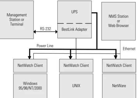
The following diagram shows how the BestLink Adapter can be used in a network application.
Ethernet Management
Station or Terminal
RS-232
UPS
BestLink Adapter
NMS Station or Web Browser
Power Line
NetWare UNIX
Windows 95/98/NT/2000
NetWatch Client NetWatch Client NetWatch Client
C H A P T E R
2
I
NSTALLATION
Installing the Internal BestLink Adapter
C A U T I O N
Before installing or removing the BestLink SNMP/WEB Adapter, the UPS MUST be turned off. Hot-swapping is prohibited.
To install the internal BestLink SNMP/WEB Adapter, perform the following steps:
1. Remove the BestDock cover on the UPS rear panel. Retain the screws.
2. Install one of the mounting plates on the BestLink Adapter according to your UPS model. Use the supplied screw to secure the mounting plate to the adapter.
Any one of the three tabs can be removed from the three-tab mounting plate so that the adapter fits securely into the UPS slot.
3. To prevent electrostatic discharge (ESD), place one hand on a metal surface such as the UPS rear panel.
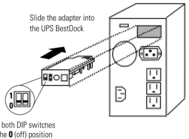
Slide the BestLink Adapter into the open slot and secure with the screws removed in Step 1 (see Figure 2).
Installation
Set both DIP switches to the0(off) position
1 0
Slide the adapter into the UPS BestDock
Figure 2. Installing the Internal BestLink Adapter
4. Set both DIP switches on the adapter to the0(off) position.
5. Connect an active 10BaseT cable to the network connector on the BestLink Adapter.
NOTE For an internal BestLink Adapter in a FERRUPS 0800, Axxium Pro, or Powerware 9170 UPS, you MUST change the Config BestDock parameter for that UPS to BestDock 1 or 2 as applicable. Refer to the UPS user’s guide for detailed instructions on how to change the parameter through the UPS front panel configuration menu.
6. Continue to “Configuration” on page 6.
Installing the External BestLink Adapter
To install the external BestLink SNMP/WEB Adapter, perform the following steps:
1. Verify that the UPS is turned off.
2. Use the supplied serial cable labeled “UPS” to connect the UPS port on the BestLink Adapter to the UPS communication port.
If connecting to a FERRUPS model with a DB-25S communication port, you must also use the supplied DB-9 to DB-25 adapter labeled INT-0013B.
Installation
4. Connect an active 10BaseT cable to the network connector on the BestLink Adapter.
5. Insert the power adapter DC power plug into the power connector on the back of the BestLink Adapter (labeled 12 VDC).
6. Plug the power adapter into a UPS output receptacle.
7. Continue to the following section “Configuration.”
Set both DIP switches to the0(off) position
1 0 Cable labeled “UPS” to
UPS serial port and BestLink Adapter UPS port
Power cable to BestLink Adapter power inlet and UPS receptacle To LAN port
Installation
Configuration
You must configure the BestLink SNMP/WEB Adapter before you can use it. There are two ways to configure the adapter:
: locally through the serial communication port
: remotely using a web browser or telnet utility
Configuring the Adapter Locally
The adapter has a configuration program that you can access by using a serial cable to connect the adapter to a terminal or a computer with a terminal emulation program.
If you choose to configure your adapter locally, see “Local Configuration” on page 7.
Configuring the Adapter Remotely
You can configure the adapter remotely through a network using a web browser or telnet utility.
NOTE Security-related parameters and some hardware parameters cannot be configured from a web browser, but can be changed from the telnet utility.
If you choose to configure your adapter remotely, see “Remote Configuration” on page 15.
C H A P T E R
3
L
OCAL
C
ONFIGURATION
Use the following procedure to use the adapter’s configuration program through a serial port.
Before You Start
To use the configuration screens for the adapter, you need:
: The serial configuration cable included in the adapter package.
: A terminal with a serial communication port, or a PC with a terminal emulation program such as HyperTerminal9
The serial line should be set to 9600 baud, No parity, 8 data bits, 1 stop bit, and no flow control.
Local Configuration
Connecting the BestLink SNMP/WEB Adapter
To connect the adapter to the terminal and start the configuration program:
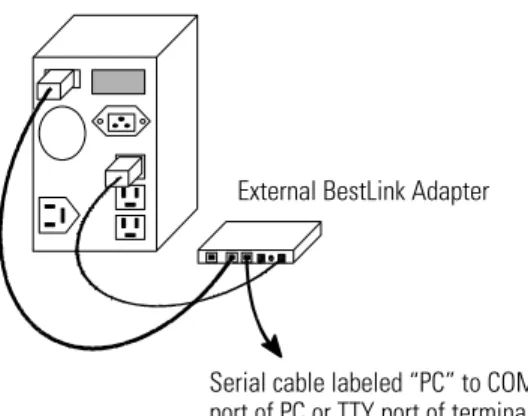
1. If configuring an external BestLink Adapter, connect the supplied serial cable labeled “PC” to the PC port on the BestLink Adapter (see Figure 4).
If configuring an internal BestLink Adapter, connect the serial cable supplied with the UPS (INT-0062) to the communication port on the UPS (see Figure 5).
Serial cable labeled “PC” to COM port of PC or TTY port of terminal
External BestLink Adapter
Figure 4. Cable Connection with External BestLink Adapter
Internal BestLink Adapter
Serial cable (INT-0062) from UPS to COM port of PC or TTY port of terminal
Figure 5. Cable Connection with Internal BestLink Adapter
2. Plug the other end of the serial cable into the serial port on your computer or terminal.
3. Verify that both DIP switches on the adapter are set to the0(off) position.
Local Configuration
4. Turn on the UPS.
After a few seconds the PC displays a message indicating that the adapter is ready.
5. Press [Enter]. The Password screen appears (see Figure 6). If the Password screen does not appear, press [Enter] again. If you still do not see the Password screen, check the following conditions:
: The communication settings of the terminal should be 9600 baud, No parity, 8 bits, and 1 stop bit.
: If the serial configuration is correct, check the cabling to verify all connections are secure.
: Verify that your terminal program is on the correct communication port for the serial connection.
: Verify that the UPS has input power and is turned on.
6. Type yourpassword(the default password is admin) and press [Enter]. The Main Menu screen appears.
+============================================================================+
| [ BestLink SNMP/WEB Adapter Configuration Utility ] |
+============================================================================+
Enter Password: *****
+============================================================================+
| [ BestLink SNMP/WEB Adapter Configuration Utility ] |
+============================================================================+ 1. SNMP/WEB Card Settings
2. Reset Configuration to default 3. Restart SNMP/WEB Card
0. Exit
Please Enter Your Choice =>_
Local Configuration
Configuring the Adapter
To configure the adapter:
1. Type1to enter the SNMP/WEB Adapter Settings screen (see Figure 7).
+============================================================================+
| [ BestLink SNMP/WEB Adapter Configuration Utility ] |
+============================================================================+ 1. SNMP/WEB Card Settings
2. Reset Configuration to default 3. Restart SNMP/WEB Card
0. Exit
Please Enter Your Choice =>1
+============================================================================+
| [ BestLink SNMP/WEB Adapter Configuration Utility ] |
+============================================================================+ 1. Set the IP Address, Gateway Address and MIB System Group
2. Set SNMP/WEB Card Control Group 3. Set Write Access Managers 4. Set Trap Receivers
5. Set IP Addresses of Primary and Secondary Date Server 6. UPS Event Actions
7. Set UPS Information
8. Set Superuser Name and Password 9. Email Notification
0. Back to Main Menu
Please Enter Your Choice =>_
Figure 7. SNMP/WEB Adapter Settings Screen
2. Type1to enter the Set the IP Address, Gateway Address and MIB System Group menu. Enter the appropriate settings for your network (see page 12).
3. Change any other options as needed for your particular configuration by typing the corresponding number shown in the menu (2through
9). Each setting is described in the following sections.
Local Configuration
5. Type0to exit the BestLink Adapter configuration. The BestLink Adapter automatically reboots and saves all settings after exiting the configuration function (see Figure 8).
NOTE The BestLink Adapter may take up to two minutes to reboot. Please wait before attempting communication with the adapter from a web browser or NMS.
NOTE Telnet Operation– Once the adapter is reachable on the network, you can use a telnet utility to adjust any of the configuration settings. The menus are identical to those seen during serial configuration and are password-protected for Superuser access only.
NOTE For an Internal BestLink Adapter– In a FERRUPS 0800, Axxium Pro, or Powerware 9170 UPS, you MUST change the Config BestDock parameter for that UPS back to NO or UPS as applicable. Refer to the UPS user’s guide for detailed instructions on changing the parameter through the UPS front panel configuration menu.
+============================================================================+
| [ BestLink SNMP/WEB Adapter Configuration Utility ] |
+============================================================================+ 1. Set the IP Address, Gateway Address and MIB System Group
2. Set SNMP/WEB Card Control Group 3. Set Write Access Managers 4. Set Trap Receivers
5. Set IP Addresses of Primary and Secondary Date Server 6. UPS Event Actions
7. Set UPS information
8. Set Superuser Name and Password 9. Email Notification
0. Back to Main Menu
Please Enter Your Choice =>0
+============================================================================+
| [ BestLink SNMP/WEB Adapter Configuration Utility ] |
+============================================================================+ 1. SNMP/WEB Card Settings
2. Reset Configuration to default 3. Restart SNMP/WEB Card
Local Configuration
Set the IP Address, Gateway Address and MIB System Group
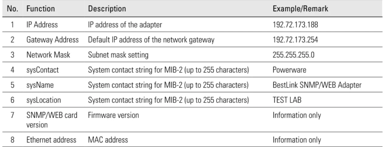
Use this function (option1) to set the IP address, the gateway address, or the management information base (MIB) parameters of the adapter, as listed in Table 1.
Table 1. IP Address, Gateway Address, and MIB System Group Parameters
No. Function Description Example/Remark
1 IP Address IP address of the adapter 192.72.173.188 2 Gateway Address Default IP address of the network gateway 192.72.173.254 3 Network Mask Subnet mask setting 255.255.255.0 4 sysContact System contact string for MIB-2 (up to 255 characters) Powerware
5 sysName System contact string for MIB-2 (up to 255 characters) BestLink SNMP/WEB Adapter 6 sysLocation System contact string for MIB-2 (up to 255 characters) TEST LAB
7 SNMP/WEB card version
Firmware version Information only 8 Ethernet address MAC address Information only
Set SNMP/WEB Card Control Group
For those users who intend to use BOOTP/DHCP, telnet, or secure HTTP in order to configure, control, update, or manage the adapter, certain control parameters must be enabled or disabled. Use this function to modify those parameters (option2).
NOTE To prevent unauthorized viewing of the web pages presented by the BestLink SNMP/WEB Adapter, use this function to enable HTTP Security Control.
Set Write Access Managers
For those users who intend to use an SNMP-compatible network management system (NMS) to manage the BestLink Adapter, the IP address of the
management station must be added in the list on the BestLink Adapter in order to receive write access rights. Use this function to add or delete the IP address of the management station (option3).
Local Configuration
Set Trap Receivers
For those users who intend to use an SNMP-compatible NMS to manage the BestLink Adapter, the IP address of the machine intended to be the trap receiver must be added in the list on the BestLink Adapter. Use this function to add or delete the IP address of the trap receivers (option4).
Set IP Addresses of Primary and Secondary Date Server
Use this function to set the IP addresses of the primary and secondary date servers (option5). Making changes to these parameters is allowed via the HTML interface for easy updating. To reset the adapter to the default values (0.0.0.0), you must program the BestLink SNMP/WEB Adapter via the serial configuration to “Reset Configuration to Default.”
NOTE Resetting the adapter changes the entire BestLink Adapter configuration to the default values.
Computer systems with the BestLink Adapter-compatible NetWatch client software are periodically monitored by the BestLink Adapter to maintain a consistent date and time with your network. Failing to program the primary and secondary date server parameters to some value other than 0.0.0.0, causes the BestLink Adapter to check all NetWatch clients (if present on the
network) for the best average time.
UPS Event Actions
Use this function to configure actions that the BestLink SNMP/WEB Adapter performs during AC Fail and Low Battery events (option6). This information is accessible via the HTTP interface for easy modification after the adapter is on the network.
Set UPS Information
Use this function to enter additional information about the UPS including date of installation and date of last battery replacement (option7). In
addition, set timing values relating to the shutdown and restart of the UPS via this function. This information is accessible via the HTTP interface for easy modification after the adapter is on the network.
Local Configuration
Set Superuser Name and Password
Use this function to set or change the user name and password of the administrators who will use a web browser to configure the BestLink SNMP/WEB Adapter (option8).
E-mail Notification
Use this function to inform selected e-mail accounts of events and changes in the status as they occur in the UPS or to provide a daily status message at a predetermined time (option9).
Back to Main Menu
C H A P T E R
4
R
EMOTE
C
ONFIGURATION
Use the following procedure to use the adapter’s configuration program through a web browser.
NOTE Verify that an active 10BaseT cable is connected to the adapter’s network connector.
Add a Routing Condition in the PC
If the IP address of the PC is on the same network with the BestLink Adapter, you may just run the web browser directly.
If the IP address of the PC is not in the same network with the BestLink Adapter (only required while configuring the adapter), you can use the Add Routing command.
1. Turn on the PC and set up the TCP/IP protocol if needed.
2. Enter the following command to add a routing condition:
Route add 192.168.7.18 192.72.173.20
where 192.72.173.20 is an example IP address for the PC and 192.168.7.18 is the default IP address of the adapter.
NOTE Refer to your operating system documentation for additional details on how to add a routing condition.
Remote Configuration
Running the Web Browser
Locate a computer (PC, host, or server) that has a web browser (Netscape or Internet Explorer recommended) and is connected to a network.
1. Run the web browser and connect to the BestLink Adapter IP address (the default is 192.168.7.18).
2. The home page of the BestLink Adapter appears (see Figure 9).
Remote Configuration
Setup Network Configuration
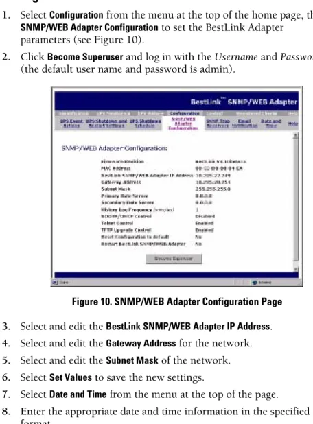
1. SelectConfigurationfrom the menu at the top of the home page, then
SNMP/WEB Adapter Configurationto set the BestLink Adapter parameters (see Figure 10).
2. ClickBecome Superuserand log in with theUsernameandPassword
(the default user name and password is admin).
Figure 10. SNMP/WEB Adapter Configuration Page
3. Select and edit theBestLink SNMP/WEB Adapter IP Address.
4. Select and edit theGateway Addressfor the network.
5. Select and edit theSubnet Maskof the network.
6. SelectSet Valuesto save the new settings.
7. SelectDate and Timefrom the menu at the top of the page.
8. Enter the appropriate date and time information in the specified format.
C H A P T E R
5
UPS P
OWER
M
ANAGEMENT
You can manage the UPS from a web browser or from an SNMP network management system.
UPS Management from a Web Browser
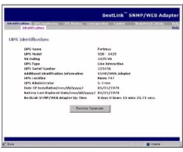
When using a web browser to access the BestLink SNMP/WEB Adapter, the majority of UPS-related information is available by selecting any of the following menu options:
: Identification
: UPS Monitoring
: UPS History
: Configuration
: Control
: Registered Clients
: Help
Each menu and submenu selection has online help available.
Becoming a Superuser
Several menus allow UPS and BestLink Adapter parameters to be modified by the user. However, many of these are password-protected for the Superuser. To become a Superuser, you must log in with a user name and provide a password. Both are configurable by serial or telnet connection. The default user name and password are admin.
NOTE Once you have become a Superuser, it is important to completely exit the browser if you wish to set the security level back to the standard read-only level.
UPS Power Management
Turning the UPS On and Off
The BestLink SNMP/WEB Adapter supports the ability to remotely turn off the UPS and its supported load. It also supports the ability to reboot the UPS (cycling output power off and then back on), as well as the ability to schedule shutdowns and restarts on a predetermined basis.
SelectingControlfrom the menu at the top of the home page provides a page that allows the Superuser to turn the UPS off. In addition, you may initiate a battery test and enable or disable any scheduled shutdowns or startups as specified in the UPS shutdown schedule table (accessed from the
Configuration menu).
Forcing the UPS to Shut Down
1. SelectConfigurationfrom the menu at the top of the home page, then
UPS Shutdown and Restart Settings.
2. Verify thatUPS to Shut Down following Client OS Shutdownis set toYES.
3. Log in as a Superuser.
4. Set the appropriateDelay Before Shutdownin minutes to ensure that any NetWatch clients and their respective operating systems have enough time to complete their shutdown. The default is three minutes, but you may wish to increase or decrease this value as appropriate for your system.
5. If you want to shut off the UPS and have it stay off (requiring local interaction to turn it back on), changeRestart UPS once AC Power ReturnstoNO.
If you want to effectively reboot the UPS and the associated load, then setRestart UPS once AC Power ReturnstoYES. The UPS will automatically restart when utility power returns after a brief delay.
6. After choosing the desired values, selectSet Valuesto update the BestLink Adapter with the new information.
7. You may then selectControlfrom the menu at the top of the home page and selectTurn UPS Off.
8. To initiate the shutdown sequence, selectSet Valueswhich instructs the BestLink Adapter to send the appropriate information to the UPS and any clients running the NetWatch shutdown client software.
UPS Power Management
C A U T I O N
SelectingTurn UPS Offturns off the output of the UPS. Any equipment powered by the UPS shuts down, as well as the external BestLink Adapter. Prepare the protected equipment for the shutdown. If you selectTurn UPS OffwithRestart UPS once AC Power Returnsset to
NO, you will have to manually restart the UPS after the shutdown occurs.
Planning a Scheduled UPS Shutdown and Restart
You may use the BestLink Adapter to schedule the day of the week and time of a shutdown and a restart. The ability to schedule shutdowns and restarts is UPS dependent, so consult your UPS documentation for more information.
1. SelectConfigurationfrom the menu at the top of the home page, then
UPS Shutdown Schedule.
2. You may configure up to seven event pairs. Enter the upcoming
Shutdown DayandShutdown Time, and if needed, theRestart Dayand
Restart Time. Times are in 24-hour format based on the date and time set within the BestLink Adapter. You must login as a Superuser to update the BestLink Adapter and selectSet Values.
3. Once the values are set, selectControlfrom the menu at the top of the home page.
4. Then selectEnable UPS Shutdown Schedule, followed bySet Valuesto start the process. Any shutdown/restart events repeat until you change the table or selectDisable UPS Shutdown Schedule.
NOTE Before scheduling any shutdowns or startups, you must configure the date and time within the BestLink Adapter.
Configuring E-mail Notification
You may use the BestLink Adapter to inform selected e-mail accounts of events and changes in status as they occur in the UPS or to provide a daily status message at a predetermined time.
1. SelectConfigurationfrom the menu at the top of the home page, then
UPS Power Management
3. If you entered a host name for theMail Server, you must enter the IP address of your network DNS Server in theDNS Addressblock.
4. To receive a daily status report, enter the time of day to send the e-mail (in 24-hour format).
5. Enter theMail Account,Description,Mail Type,Event Level, andEvent Typefor each recipient. Refer to the online help file for more details on each of these fields.
6. SelectSet Valuesto save your changes.
Performing a Manual UPS Battery Test
You can use the BestLink Adapter to manually perform a UPS battery test. The ability to test the UPS is model dependent, so consult your UPS
documentation for more information.
1. To manually start a battery test on a specific UPS, selectControlfrom the menu at the top of the home page.
2. Become a Superuser and then selectInitiate Battery Test, followed by
Set Valuesto start the process.
3. To stop the test while in progress, you can selectCancel Battery Test
followed bySet Values.
Scheduling a UPS Battery Test
You can use the BestLink Adapter to perform a UPS battery test on a user-defined schedule.
1. To schedule a battery test on a specific UPS, selectControlfrom the menu at the top of the home page.
2. SelectBattery Test Schedule.
3. Become a Superuser and then select theTest DayandTest Time(in 24-hour format) for the test to be initiated by the BestLink Adapter. The test is performed each week on the specified day and time until theTest Dayis changed toDisabled.
UPS Power Management
Viewing the UPS History Logs
SelectingUPS Historyfrom the menu at the top of the home page allows you to choose the currentUPS Data LogandUPS Event Log. The data log provides numerical data logged once a minute from the UPS. The event log contains text messages regarding the status of the UPS and the BestLink Adapter. Past data and event logs are also accessible, as well as a data log applet that displays the data in a graphical format.
Viewing the UPS Status with CheckUPS-like Applet
SelectingUPS Monitoringfrom the menu at the top of the home page, followed byStatus Appletprovides the user with a CheckUPS-like display that provides analog meters representing UPS data, as well as the current status of the UPS and past events that have happened while the applet has been running. The meters and status update automatically as new information is obtained from the UPS.
UPS Management from an SNMP NMS
To access the BestLink SNMP/WEB Adapter via SNMP, use the following steps:
1. Use these Community strings:
GET Community string: public or user password (default is admin). SET Community string: user password (default is admin).
NOTE Only NMSs whose IP address is present in the NMS table are allowed to perform a set. To add an NMS to the table, use the Serial (or telnet) Configuration menu.
2. Thebestpwr2.mibfile (supplied on the floppy disk) contains the MIB for the BestLink Adapter. Add this file to the MIB database of your SNMP management software (such as HP OpenView, IBM NetView9
6000, and Sun NetManager).
3. Using the Facilities provided by the SNMP management software, you may now access the individual MIB objects. Reference the MIB found on the floppy disk for more information.
UPS Power Management
Viewing UPS Monitoring Parameters
The BestLink SNMP/WEB Adapter supports several MIB groups that separate specific UPS parameters into related areas. The groups used in the MIB for the BestLink Adapter include:
: Ident
: Battery
: Input
: Output
: Config
: Control
: Test
: Alarms
Forcing the UPS to Shut Down
The BestLink SNMP/WEB Adapter supports MIB groups containing objects that enable the user to shut down and restart the UPS.
Receiving Event Traps
The BestLink SNMP/WEB Adapter supports several event-related traps, that can be reported to the SNMP network management software. Reference the MIB files found on the included floppy disk for more information.
UPS Power Management
Automatic Shutdown of UPS-Protected Computers
NetWatch client software supports remote UPS monitoring and automatic shutdown of UPS-protected computer systems and is available on the Invensys Software Suite CD-ROM or from www.powerware.com. Clients are available for the following operating systems:
: Windows 95/98/NT/2000
: Novell NetWare
: UNIX (various versions)
Each NetWatch client uses its IP address to register with a specified BestLink SNMP/WEB Adapter via the network. Once a client has registered, any change in UPS status is communicated to NetWatch. Depending on the operating system, NetWatch typically alerts the user(s) whenever the UPS begins supplying AC power from its batteries (for example, the AC line fails). Then, if AC line power does not return and the remaining battery time is low, NetWatch takes over and completes an operating system shutdown prior to the UPS running out of battery power.
C H A P T E R
6
A
PPENDIX
The appendix contains the BestLink Adapter specifications, components and diagrams, pin assignments, upgrading the firmware, service and support, and the warranty.
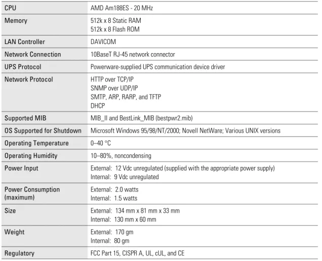
Table 2. Technical Specifications
CPU AMD Am188ES - 20 MHz
Memory 512k x 8 Static RAM 512k x 8 Flash ROM
LAN Controller DAVICOM
Network Connection 10BaseT RJ-45 network connector
UPS Protocol Powerware-supplied UPS communication device driver
Network Protocol HTTP over TCP/IP SNMP over UDP/IP SMTP, ARP, RARP, and TFTP DHCP
Supported MIB MIB_II and BestLink_MIB (bestpwr2.mib)
OS Supported for Shutdown Microsoft Windows 95/98/NT/2000; Novell NetWare; Various UNIX versions
Operating Temperature 0–40 °C
Operating Humidity 10–80%, noncondensing
Power Input External: 12 Vdc unregulated (supplied with the appropriate power supply) Internal: 9 Vdc unregulated
Power Consumption (maximum)
External: 2.0 watts Internal: 1.5 watts
Size External: 134 mm x 81 mm x 33 mm Internal: 130 mm x 60 mm
Appendix
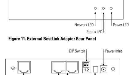
Adapter Components
The adapter front and rear panel details are shown in the following figures.
Power LED Status LED
Network LED
Figure 11. External BestLink Adapter Rear Panel
DIP Switch
UPS Port
Network Connector PC Port Reset Button Power Inlet
Figure 12. External BestLink Adapter Rear Panel
Status LED
Network Connector Network LED
DIP Switch
Appendix
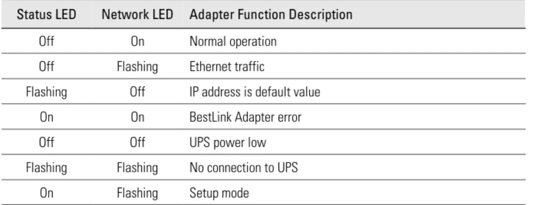
LED Description
The functions of the BestLink Adapter are indicated by the Status and Activity LEDs, as listed in Table 3.
Table 3. LED Definitions
Status LED Network LED Adapter Function Description
Off On Normal operation Off Flashing Ethernet traffic
Flashing Off IP address is default value On On BestLink Adapter error Off Off UPS power low Flashing Flashing No connection to UPS
On Flashing Setup mode
DIP Switch Description
DIP switch definitions for both types of the BestLink Adapters are listed in Table 4.
Table 4. DIP Switch Modes
SW1 SW2 Description
Off Off Operational Mode (default) Off On Manufacturing Diagnostic Mode On Off Reserved
Appendix
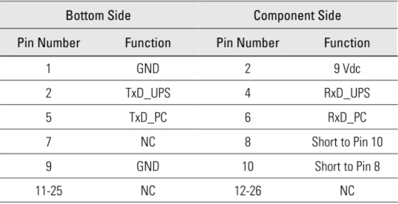
Pin Assignments
DIP Switch LEDs
Network Connector PCB Edge
Connector
Figure 14. Internal BestLink Adapter Component Layout Table 5. PCB Edge Connector Pin Assignments
Bottom Side Component Side
Pin Number Function Pin Number Function
1 GND 2 9 Vdc
2 TxD_UPS 4 RxD_UPS
5 TxD_PC 6 RxD_PC
7 NC 8 Short to Pin 10 9 GND 10 Short to Pin 8
Appendix
Serial Cable Definition
Table 6. External BestLink Adapter to UPS Serial Connection Function Description RJ-45 DB-9 (Male)
Ready to Send 1
-Data Terminal Ready 2 -Transmitted Data 3 1
Signal Ground 4 4
Chassis Ground 5 Case GND
Received Data 6 2
Data Set Ready 7
-Clear to Send 8
-Table 7. External BestLink Adapter to PC Serial Connection Function Description RJ-45 DB-9 (Female)
Ready to Send 1
-Data Terminal Ready 2 -Transmitted Data 3 2
Signal Ground 4 5
Chassis Ground 5 Case GND
Received Data 6 3
Data Set Ready 7
-Appendix
Upgrading the BestLink Adapter Firmware
During the upgrade process, the BestLink Adapter is inaccessible, but restarts automatically within a minute after completing the upgrade.
To upgrade the firmware, use the following steps:
1. Locate a networked PC with Windows 95, 98, NT, or 2000.
2. Copy the supplied Firmware Upgrade Utility (blupgrade.exe) program to the PC.
3. Run the Upgrade Utility from Windows by selectingStart,Run, and then entering the path and filenameblupgrade.exe.
4. Assuming that the network (TCP/IP) connection for the PC can reach the BestLink Adapter needing the firmware upgrade, select
Discoverwhich instructs the utility to attempt to find all reachable BestLink Adapters on the network. Any adapters that are found are displayed in the table.
5. Before an upgrade can be performed, select the desired adapters from the display list and enter the Superuser name and password.
Select the BestLink Adapter to be upgraded (up to four adapters at a time under most network conditions) by activating the checkbox for each adapter’s IP address. Those that have not been selected in this manner are not upgraded.
6. SelectOpennext toFilenameand select the binary upgrade file that you would have previously downloaded or otherwise received and copied to the PC.
SelectUpgradeto start the process. Once the process starts, do not cancel or interrupt the upgrade process. Otherwise, the BestLink Adapter receives a corrupted image, preventing the adapter from operating correctly.
7. When the Upgrade Utility completes, exit the program by selecting
Appendix
Service and Support
If you have any questions or problems with the UPS, call yourLocal Distributor
or theHelp Deskat one of the following telephone numbers and ask for a UPS technical representative.
In the United States: 1-800-365-4892or1-919-870-3149 Europe, Middle East, Africa: +44-17 53 608 700
Asia: +852-2830-3030
Australia: +61-3-9706-5022
Please have the following information ready when you call the Help Desk:
: Model number
: Serial number
: Version number (if available)
: Date of failure or problem
: Symptoms of failure or problem
: Customer return address and contact information
If repair is required, you will be given a Returned Material Authorization (RMA) Number. This number must appear on the outside of the package and on the Bill Of Lading (if applicable). Use the original packaging or request packaging from the Help Desk or distributor. Units damaged in shipment as a result of improper packaging are not covered under warranty. A replacement or repair unit will be shipped, freight prepaid for all warrantied units.
NOTE For critical applications, immediate replacement may be available. Call theHelp Desk
Appendix
Two-Year Limited Warranty (US and Canada Only)
Powerware Corporation warrants the electronics of the BestLink SNMP/WEB Adapter to be free from defects in material and workmanship for a period of two years from Date of Purchase. If, in Powerware Corporation’s opinion, the electronics fails to meet its published specifications due to a defect in material and workmanship covered by this warranty, Powerware Corporation will repair or replace the warranted Unit at no cost to the customer for parts and labor.
Equipment supplied by Powerware Corporation, but not manufactured by Powerware Corporation, is warranted solely by the manufacturer of such equipment. Powerware Corporation does not warrant equipment not manufactured by Powerware Corporation.
This warranty does not apply to any Unit that has been subject to neglect, accident, abuse, misuse, misapplication, incorrect connection or that has been subject to repair or alteration not authorized in writing by Powerware Corporation’s personnel. THIS WARRANTY IS THE PURCHASER’S (USER’S) SOLE REMEDY AND IS EXPRESSLY IN LIEU OF ANY OTHER WARRANTY, AND THERE ARE NO OTHER EXPRESSED OR IMPLIED GUARANTEES OR WARRANTIES (INCLUDING ANY IMPLIED WARRANTY OF MERCHANTABILITY OR FITNESS FOR PURPOSE). In no case will Powerware Corporation’s liability under this contract exceed the value of the Unit furnished.
In no event shall Powerware Corporation be liable for any indirect, incidental, special or consequential damages. Powerware Corporation shall not be responsible for failure to provide service or parts due to causes beyond Powerware Corporation’s reasonable control. THIS LIMITED WARRANTY IS VOID UNLESS USER RETURNS TO POWERWARE CORPORATION THE INCLUDED WARRANTY REGISTRATION CARD WITHIN THIRTY (30) DAYS OF DELIVERY.
Any advice furnished the Purchaser (User) before or after delivery in regard to use or application of Powerware Corporation equipment is furnished without charges and on the basis that it represents Powerware Corporation’s best judgement under the circumstances. The use of any such advice by the Purchaser (User) is solely and entirely at his or her own risk. This limited warranty applies only to equipment installed in the fifty United States of America and Canada. In other countries, consult your local distributor.
Extended Service Coverage
A full complement of warranty extensions and enhancements are available from Powerware Corporation for your UPS. Information pertaining to these services should be available in the shipping container along with this manual. If not, or if you would like more information, call the Powerware CorporationHelp Deskand ask about warranty services.
Appendix
International Limited Warranty
Powerware Corporation warrants the electronics modules manufactured by Powerware Corporation (“Unit”) and batteries originally packaged in the Unit or in battery packs manufactured by Powerware Corporation against defect in material or workmanship until the earlier of: (1) 18 months from date of shipment or (2) 12 months from date of initial start-up is performed by Powerware Corporation field personnel or field personnel authorized by Powerware Corporation to carry out such service efforts on its behalf and provided that, startup occurs no later that 6 months after shipment. If the unit does not function in accordance with its published specification, the user should give Powerware Corporation prompt notice thereof and if requested by Powerware Corporation, the user shall return the warranted Unit or parts thereof to the plant or service station designated by Powerware Corporation for inspection by Powerware Corporation. Any Unit which may require repair and/or replacement of parts as the result of defects in workmanship or material within the stated warranty period, will be replaced or repaired at Powerware Corporation’s option without charge for replacement parts. The cost of shipment, duties or all other expenses associated with shipment of repaired or replaced items is for the account of the user. Powerware Corporation will not be responsible or liable for work done or expense incurred in connection with repair or replacement except as expressly authorized by Powerware Corporation, Raleigh, NC, USA in writing. If a service engineer is required, labor, at current published rates, and all travel and living expenses are for the account of the user.
Powerware Corporation does not warrant equipment not manufactured by Powerware Corporation including any battery not originally packaged with the Unit or in battery packs manufactured by Powerware Corporation. The manufacturer of all such equipment shall solely warrant that equipment and Powerware Corporation shall have no responsibility or liability thereof.
IT IS AGREED THAT Powerware Corporation, ITS PARENT COMPANY, OR ANY OF THEIR AFFILIATES, SHALL HAVE NO LIABILITY FOR INDIRECT, INCIDENTAL, SPECIAL, OR CONSEQUENTIAL DAMAGES, AND THAT THERE IS NO WARRANTY, EITHER EXPRESSED OR IMPLIED BY LAW OR THE PARTIES HERETO, OTHER THAN THOSE
EXPRESSLY SET FORTH HEREIN. THIS WARRANTY DOES NOT COVER DAMAGE TO THE UNIT CAUSED BY MISUSE, ABUSE, NEGLECT, UNAUTHORIZED MODIFICATIONS, IMPROPER MAINTENANCE, ACCIDENTS OR OTHER ABNORMAL CONDITIONS.
Force Majeure
Powerware Corporation shall not be liable for any delays or defaults hereunder by reason of fire, floods, acts of God, labor troubles, accidents to machinery, delays of carriers or suppliers, inability of suppliers to supply, the impositions of priorities, restrictions or other acts of government, or other causes beyond its reasonable control.