Citrix XenDesktop 7.1 on
Microsoft Hyper-V Server
2012 R2 on Cisco UCS
C-Series Hardware
Solution Design
Citrix Validated Solutions
July 10
th2014
Prepared by: APAC Solutions
1
TABLE OF CONTENTS
Section 1:
Executive Summary ... 4
Project Overview ... 5
Reference Architecture ... 5
Audience ... 5
Purpose ... 5
Architecture Overview ... 6
Citrix Virtual Desktop Types ... 6
The Pod Concept ... 6
Justification and Validation ... 7
Citrix Validated Solution Overview ... 8
Citrix Validated Solution Layered Architecture ... 11
Design Recommendations ... 12
Logical Architecture Overview ... 13
Scale Out Guidance for HSD ... 15
Scale Out Guidance for HVD ... 20
Solution at a Glance ... 25
Section 2:
Design ... 27
User Layer Design ... 28
User Topology ... 28
Endpoints ... 28
Access Layer Design ... 29
Desktop Layer Design ... 30
User Personalisation ... 30
Applications ... 31
Master Image ... 33
Control Layer Design ... 36
Infrastructure ... 37
Delivery Controllers (XenDesktop) ... 41
Access Controllers (StoreFront) ... 47
Hypervisor Layer ... 48
Hyper-V Overview ... 48
HSD Hyper-V Host ... 48
2
Hyper-V Hardware Details ... 49
Hyper-V General Details ... 49
Hyper-V Network Details ... 51
Hyper-V Storage Details ... 53
System Center Virtual Machine Manager ... 56
VMM General Details ... 56
VMM Network Details ... 56
VMM Guest Virtual Machine Details ... 57
Network Layer... 58
Overview ... 58
Network Components ... 58
VLAN Information ... 59
DHCP ... 59
Hardware Layer Design ... 60
Physical Architecture Overview ... 60
Physical Component Overview ... 62
Server Hardware ... 62
Bill of Materials - Hosted Shared Desktops ... 64
Bill of Materials - Hosted Virtual Desktops ... 65
Windows File Services ... 66
File Servers ... 68
DFS-Namespace ... 69
DFS-Replication ... 70
Section 3:
Appendices ... 71
Appendix A. Further Decision Points ... 72
Appendix B. Server Inventory ... 74
HSD Servers (Support up to 1,000 User Desktop Sessions) ... 74
HVD Servers (Support up to 1,000 Virtual Desktop Sessions) ... 75
Appendix C. Network Switch Requirements ... 76
Switch Requirements ... 76
Network Port Densities ... 76
Appendix D. IP Addressing ... 77
Hyper-V Hosts: ... 77
Control Layer Guest VMS: ... 77
3
Sample HVD DHCP Scopes for up to 1,000 sessions: ... 78
Appendix E. Service Accounts & Groups ... 79
Role Groups ... 79
Service Accounts ... 79
Appendix F. XenDesktop Policies ... 80
CVS Test Environment Policy Settings ... 80
Appendix G. Cisco C240 M3 SFF Server BIOS Settings ... 81
Processor ... 81
Memory ... 82
Appendix H. Storage Calculations ... 83
HSD Shared Infrastructure and Desktop Node ... 83
HVD Shared Infrastructure and Desktop Node ... 83
Appendix I. Test Results Validation ... 84
End User Experience Monitoring ... 84
Appendix J. References ... 87
Citrix ... 87
Cisco C-Series ... 87
4
SECTION 1: EXECUTIVE
SUMMARY
5
Project Overview
Reference Architecture
In order to facilitate rapid and successful deployment of the Citrix XenDesktop FlexCast models, Citrix Consulting APAC have built and tested a solution using the components described in this document. The Citrix Validated Solution (‘CVS’) provides prescriptive guidance for these
components including design, configuration and deployment settings thereby allowing customers to quickly deploy a desktop virtualization solution using Citrix XenDesktop.
Validation was performed by extensive testing using Login VSI to simulate real-world workloads and determine optimal configuration for the integration of components that make up the overall solution.
Audience
This reference architecture document is created as part of a Citrix Validated Solution and is intended to describe the detailed architecture and configuration of the components contained within. Readers of this document should be familiar with Citrix XenDesktop, its related technologies and the foundational components, Cisco C240 M3 High-Density Rack servers, Networking components and Microsoft Hyper-V Server® 2012 R2.
Purpose
The purpose of this document is to provide design information that describes the architecture for this Citrix Validated Solution which is based on Citrix Hosted Shared Desktop (HSD) and Citrix Hosted Virtual Desktop (HVD) FlexCast models. The solution is built on Cisco C240 M3 High-Density Rack servers. Microsoft Hyper-V Server® 2012 R2 is the hypervisor utilised to support the virtualised environment.
6
Architecture Overview
This Citrix Validated Solution and its components was designed, built and validated to support two distinct Citrix virtual desktop types. The architecture for each desktop type is described to support up to 1,000 and beyond user desktop sessions:
Hosted Shared Desktops. Shared user sessions running XenDesktop Hosted Shared Desktops on Windows Server 2008 R2 Remote Desktop Session Hosts or
Hosted Virtual Desktops. Individual user sessions running XenDesktop Hosted Virtual Desktops on Windows 7 Enterprise x64.
Each of these desktop types is described in the Citrix FlexCast model operating as virtual machine instances on Microsoft Hyper-V Server® 2012 R2. This architecture is a single, self-supporting modular component identified as a Pod, described to support up to 1,000 users sessions allowing customers to consistently build and deploy scalable environments. Additional pods may be deployed thus scaling out the proposed architecture beyond 1,000 seats.
Citrix Virtual Desktop Types
This Citrix Validated Solution document references Citrix Hosted Shared Desktops and Citrix Hosted Virtual Desktops. Both types of virtual desktops are discussed below for reference. For more information, refer to Citrix FlexCast delivery methods http://flexcast.citrix.com/
Hosted Shared Desktop (HSD). A Windows Remote Desktop Session (RDS) Host using Citrix XenDesktop to deliver Hosted Shared Desktops in a locked down, streamlined and standardised manner with a core set of applications. Using a published desktop on to the Remote Desktop Session Host, users are presented a desktop interface similar to a Windows 7 “look and feel”. Each user runs in a separate session on the RDS server. Hosted Virtual Desktop (HVD) aka Hosted VDI. A Windows 7 desktop instance running
as a virtual machine where a single user connects to the machine remotely. Consider this as 1:1 relationship of one user to one desktop. There are differing types of the hosted virtual desktop model (existing, installed, pooled, dedicated and streamed). This document exclusively refers to the pooled type of HVD.
This document will discuss for the delivery of non-persistent or state-less desktop types - Hosted Shared Desktops and Hosted Virtual Desktops (pooled desktops). Throughout this document nomenclature may reference the FlexCast model as; “<FlexCast model>” which should be substituted for either HSD or HVD as appropriate to the design under consideration.
The Pod Concept
The term “pod” is referenced throughout this solution design. In the context of this document a pod is a known entity, an architecture that has been pre-tested and validated. A pod consists of the hardware and software components required to deliver 1,000 virtual desktops using either HSD or HVD FlexCast models.
For clarity this document does not attempt to describe combining both FlexCast models, it specifically discusses each type as s single entity of up to 1,000 desktops.
7
Justification and Validation
The construct of this Citrix Validated Solution is based on many decisions that were made during validation testing. Testing was carried out using the Login VSI virtual Session Indexer (VSI), an industry standard tool for user / session benchmarking. Login VSI allows comparisons of platforms and technologies under the same repeatable load. The “Medium” VSI workload is expected to approximate the average office worker during normal activities and was the workload used throughout testing.
http://www.loginvsi.com/
Note. All workloads were tested using the XenDesktop Template Policy “High Server Scalability” running in “Legacy Graphics mode” therefore the Bill of Materials described for each FlexCast model within this document are based on the density of users with these policy settings in place. Using these Citrix Policies allows the greatest host density for each FlexCast model.
In conjunction with Login VSI, further Validation of the end user experience during test load scenarios was validated using Liquidware Labs™ Stratusphere™ UX. Stratusphere™ UX is a comprehensive set of monitoring, performance validation and diagnostics tools.
8
Citrix Validated Solution Overview
The Illustration below depicts the layers of the Citrix XenDesktop Hosted Shared Desktop technology stack utilised in the solution.
Figure 1. Citrix Validated Solution Stack depicting HSD Workloads
The Illustration below depicts the layers of the Citrix XenDesktop Hosted Virtual Desktop technology stack utilised in the solution.
9
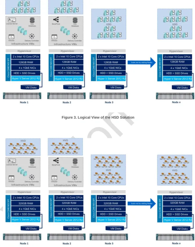
The Illustrations below depict the combined physical and logical view of the scale out architecture for both HSD and HVD platforms using the Cisco C240 M3 SFF servers.
Figure 3. Logical View of the HSD Solution
10
Citrix XenDesktop. Two virtualised Desktop Delivery Controller servers will be deployed to support the XenDesktop Site. A single XenDesktop Site will be utilised to manage the initial desktop pod.
Virtual Desktops. This solution will focus on the delivery of the two discrete virtual desktops types:
o Hosted Virtual Desktops (HVD). Describing the delivery of 1,000 Pooled Windows 7 virtual desktops powered by Citrix XenDesktop 7.1.
o Hosted Shared Desktops (HSD). Describing the delivery of 1,000 Shared virtual desktop based on Microsoft Windows Server 2008 R2 Remote Desktop Session host workloads powered by Citrix XenDesktop 7.1.
Microsoft Hyper-V Server 2012 R2 (Hyper-V). The hypervisor selected to host the virtualised desktop and server instances for this solution is Microsoft Hyper-V Server 2012® R2. Hyper-V will be deployed onto the Cisco C240 M3 SFF servers utilising local storage.
Virtual Desktop Provisioning. This document describes the use of Citrix Machine Creation Services (‘MCS’) for the provisioning of HSD and HVD guest workloads using a predefined master image containing the optimised operating system and Tier-1 application set.
Applications. Tier-21 applications which may include line of business or customer specific applications that are not embedded as part of the master disk image may be delivered using Citrix XenDesktop RDS workloads or Microsoft App-V2.
Citrix StoreFront. Virtualised StoreFront servers will be deployed to provide application and desktop resource enumeration.
Citrix Performance Management. Citrix Director and Citrix EdgeSight will provide monitoring capabilities into the virtual desktops and user sessions.
Cisco Nexus Switches. As per the test environment, a pair of Cisco Nexus 3048TP 1GbE Top of Rack (ToR) switches have been used. The Customer can opt to leverage their existing 1GbE network switch infrastructure to minimise hardware acquisition cost. Supporting Infrastructure. The following components are assumed to exist within the
customer environment and are required infrastructure components:
o Microsoft Active Directory Domain Services.
o A suitable Microsoft SQL database platform to support the solution database requirements3.
o Licensing servers to provide Microsoft licenses are assumed to exist.
o CIFS SMB File sharing is required to support User profile data. This can be provisioned as part of the solution using Windows 2012 R2 File Services.
o DHCP Services with sufficient IP addresses to support the proposed virtual desktop workloads. This can be provisioned as part of the solution using the Windows Server 2012 R2 DHCP Role.
This design document will focus on the desktop virtualisation components which include the desktop workload, desktop delivery mechanism, hypervisor, hardware, network and storage platforms.
1
The solution design for Tier-2 applications delivered by Citrix XenDesktop or Citrix XenApp is out of scope for this document.
2
The solution design of Microsoft App-V components is out of scope for this document.
3
This document provides sample sizing guidelines and the licensing requirements for the databases used in this Citrix Validated Solution; however it does not attempt to provide design guidelines for Microsoft SQL Server. The design and implementation for a highly available Microsoft SQL Server platform is required although considered out of scope for this design document.
11
Citrix Validated Solution Layered Architecture
The Citrix Validated Solution architecture breaks the design into a number of distinct layers, discussed below:
User Layer4. This layer details the user segments defined during the projects “assess phase”. Users are grouped based on their network connectivity to the data centre, recommended end point devices, security requirements, data storage needs and virtual workforce needs.
Access Layer. This layer describes how the user layer will connect to their desktop, which is hosted in the desktop layer of the architecture. Local users will connect directly to StoreFront while remote users connect via a set of firewalls that protect the internal environment. To bridge the firewalls, remote users will connect with an SSL-VPN device (Citrix Access Gateway).
Desktop Layer. This layer contains the user’s virtual desktop, broken down into FlexCast models. It is subdivided into three components, Within each sub-layer, specifics are documented detailing the operating system, assigned policies, profile design and application requirements:
o User Personalisation
o Applications
o Master Image
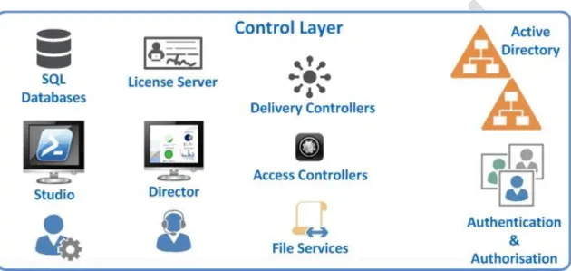
Control Layer. This layer is responsible for managing and maintaining all other layers. It provides details on the controller requirements to support the entire solution. The Control layer is broken down into the following sub sections:
o Infrastructure. The Infrastructure section is responsible for providing the
underlying resources to support each component. These resources include Active Directory, database requirements and license servers.
o Desktop Controllers. The Desktop Controllers section provides details on the components required to support the desktop layer, which include XenDesktop.
o Access Controllers. The Access Controllers section focuses on the required versions and virtualisation resources.
Hypervisor Layer. The section described the configuration for Microsoft Hyper-V Server 2012 R2. Hyper-V is a “Type 1” hypervisor that runs directly on the hardware resources described in the Hardware Layer.
Network. This section defines the physical network switching and logical connectivity requirements to support the solution.
Hardware Layer. This layer is responsible for the physical devices required to support the entire solution. It includes servers, processors, memory and storage devices. This layer is broken down into the physical and logical components and provides the Bill of Materials (BoM) to deploy the entire solution.
4
User assessment in the context of this document is for reference only. User definition and segmentation for VDI desktop types is out of scope for this document.
12
The illustration below describes the distinct layers of the architecture:
Figure 5. Architecture Layered View
Design Recommendations
Assumptions:
The following assumptions have been made:
Required Citrix and Microsoft licenses and agreements are available. Required power, cooling, rack and data centre space is available.
No network constraints that would prevent the successful deployment of this design. Microsoft Windows Active Directory Domain services are available.
Microsoft SQL Database platform is available. Certificate and/or PKI services are assumed to exist.
A current and supported version of Citrix Receiver must be deployed to ensure all features and components of the solution are at a supported level, refer to the following link for the latest Citrix Receiver Downloads.
The User layer in the context of this document is for reference only. User analysis, definition and segmentation for the use of VDI desktop types is out of scope for this document.
13
Logical Architecture Overview
This section discusses the logical architecture and concepts for the remainder of this document. From an architectural perspective Hyper-V will be deployed onto the aforementioned hardware (Hardware Layer) with the infrastructure servers (Control layer) and virtual desktops (Desktop Layer) deployed as Hyper-V virtual machine instances.
From a physical hardware perspective each server node will be configured identically as per the recommended Cisco C240 Bill of Materials. From a logical perspective the hosts for each desktop can be defined as follows.
A minimum of two sever nodes is required to establish the foundation of a Citrix XenDesktop environment complete with the necessary infrastructure server guest VMs deployed in a redundant fashion. The first two servers, Node1 and Node 2 will be referred to as Shared Infrastructure & Desktop Nodes as they will host both Infrastructure Server VMs and Desktop workloads.
The platform can be scaled-out to support additional capacity by simply adding
subsequent physical servers, referred to as Desktop nodes which will only support guest HSD or HVD desktop workloads.
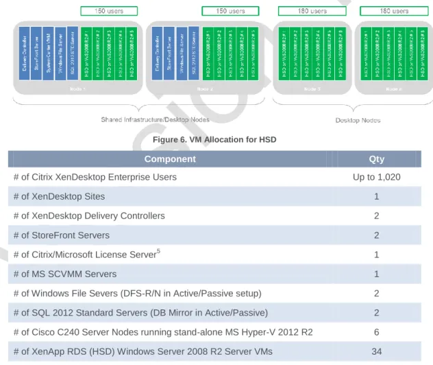
Pod of 1,000 HSD Users
The logical and physical components that make up the platform to deliver a 1,000 user Hosted Shared Desktop solution are described below:
Figure 6. VM Allocation for HSD
Component Qty
# of Citrix XenDesktop Enterprise Users Up to 1,020 # of XenDesktop Sites 1 # of XenDesktop Delivery Controllers 2 # of StoreFront Servers 2 # of Citrix/Microsoft License Server5 1 # of MS SCVMM Servers 1 # of Windows File Severs (DFS-R/N in Active/Passive setup) 2 # of SQL 2012 Standard Servers (DB Mirror in Active/Passive) 2 # of Cisco C240 Server Nodes running stand-alone MS Hyper-V 2012 R2 6 # of XenApp RDS (HSD) Windows Server 2008 R2 Server VMs 34
Table 1. 1,000 User HSD Pod Detail
5
14
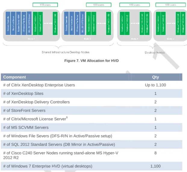
Pod of 1,000 HVD Users
The logical and physical components that make up the platform to deliver a 1,000 user Hosted Virtual Desktop solution are described below:
Figure 7. VM Allocation for HVD
Component Qty
# of Citrix XenDesktop Enterprise Users Up to 1,100 # of XenDesktop Sites 1 # of XenDesktop Delivery Controllers 2 # of StoreFront Servers 2 # of Citrix/Microsoft License Server6 1 # of MS SCVMM Servers 1 # of Windows File Severs (DFS-R/N in Active/Passive setup) 2 # of SQL 2012 Standard Servers (DB Mirror in Active/Passive) 2 # of Cisco C240 Server Nodes running stand-alone MS Hyper-V
2012 R2
8 # of Windows 7 Enterprise HVD (virtual desktops) 1,100
Table 2. 1,000 User HVD Pod Detail
6
15
Scale Out Guidance for HSD
This section outlines the sizing metrics applicable to the Cisco C240 server nodes, network switch ports, Hyper-V hosts, Infrastructure server VMs and the required Citrix and Microsoft licenses7 to stand up the HSD solution based on the suggested scale-out increment.
The solution can be scaled out incrementally by adding additional single server nodes, however in this section the scenarios depicts the addition of two server nodes for demonstration purposes. Notes on Microsoft Licensing used as per the below samples8.
# of MS Core Infrastructure Suite (CIS) Standard. MS CIS includes System Center 2012 R2 Standard and licenses for 2 x Windows Server 2012 Standard VMs or Operating System Environment). Refer to
http://www.microsoft.com/licensing/about-licensing/SystemCenter2012-R2.aspx
# of MS SQL Server 2012 Standard Server. Assumes SQL Server is licensed as a 2 VCPU (v-cores) virtual machine with MS Software Assurance. SQL Server license requires minimum of 4 core licenses. Active-Passive SQL Server deployment means no additional licenses are required for secondary passive SQL Server. Refer to
http://www.microsoft.com/licensing/about-licensing/sql2014.aspx
7
Each customer will have different Citrix and Microsoft license agreements and as such should be factored into the final configuration.
8
16
Scenario: 2 x Nodes
Hardware Components Qty Infrastructure Components Qty
# of Cisco C240 nodes 2 # of SCVMM server 1 # of RU (Cisco server nodes) 4 # of Hyper-V hosts 2 # of 1GbE Ports (Hyper-V) 8 # of XenDesktop Sites 1 # of 1GbE Ports (CIMC) 2 # of HSD users 300 Total # of 1GbE Ports 10 # of HSD Windows Server VMs 10 # of ToR 1GbE 48-port Switch 2
Table 3. Hardware Component Breakdown - 2 x Nodes
Citrix/Microsoft License Components Qty
# of Citrix XenDesktop Enterprise User/Device 300 # of MS Remote Desktop Services CALs 300 # of MS Core Infrastructure Suite Standard 10 # of MS SQL Server 2012 Standard Server 1
Table 4. Component Breakdown - 2 x Nodes
17
Scenario: 4 x Nodes
Hardware Components Qty Infrastructure Components Qty
# of Cisco C240 nodes 4 # of SCVMM server 1 # of RU (Cisco server nodes) 8 # of Hyper-V hosts 4 # of 1GbE Ports (Hyper-V) 16 # of XenDesktop Sites 1 # of 1GbE Ports (CIMC) 4 # of HSD users 660 Total # of 1GbE Ports 20 # of HSD Windows Server VMs 22 # of ToR 1GbE 48-port Switch 2
Table 5. Hardware Component Breakdown - 4 x Nodes
Citrix/Microsoft License Components Qty
# of Citrix XenDesktop Enterprise User/Device 660 # of MS Remote Desktop Services CALs 660 # of MS Core Infrastructure Suite Standard 16 # of MS SQL Server 2012 Standard Server 1
Table 6. Component Breakdown - 4 x Nodes
18
Scenario: 6 x Nodes
Hardware Components Qty Infrastructure Components Qty
# of Cisco C240 nodes 6 # of SCVMM server 1 # of RU (Cisco server nodes) 12 # of Hyper-V hosts 6 # of 1GbE Ports (Hyper-V) 24 # of XenDesktop Sites 1 # of 1GbE Ports (CIMC) 6 # of HSD users 1,020 Total # of 1GbE Ports 30 # of HSD Windows Server VMs 34 # of ToR 1GbE 48-port Switch 2
Table 7. Hardware Component Breakdown - 6 x Nodes
Citrix/Microsoft License Components Qty
# of Citrix XenDesktop Enterprise User/Device 1,020 # of MS Remote Desktop Services CALs 1,020 # of MS Core Infrastructure Suite Standard 22 # of MS SQL Server 2012 Standard Server 1
Table 8. Component Breakdown - 6 x Nodes
19
Scenario: 8 x Nodes
Hardware Components Qty Infrastructure Components Qty
# of Cisco C240 nodes 8 # of SCVMM server 1 # of RU (Cisco server nodes) 16 # of Hyper-V hosts 8 # of 1GbE Ports (Hyper-V) 32 # of XenDesktop Sites 1 # of 1GbE Ports (CIMC) 8 # of HSD users 1,380 Total # of 1GbE Ports 40 # of HSD Windows Server VMs 46 # of ToR 1GbE 48-port Switch 2
Table 9. Hardware Component Breakdown - 8 x Nodes
Citrix/Microsoft License Components Qty
# of Citrix XenDesktop Enterprise User/Device 1,380 # of MS Remote Desktop Services CALs 1,380 # of MS Core Infrastructure Suite Standard 28 # of MS SQL Server 2012 Standard Server 1
Table 10. Component Breakdown - 8 x Nodes
20
Scale Out Guidance for HVD
This section outlines the sizing metrics applicable to the Cisco C240 server nodes, network switch ports, Hyper-V hosts, Infrastructure server VMs and the required Citrix and Microsoft licenses9 to stand up the HVD solution based on the suggested scale-out increment.
The solution can be scaled out incrementally by adding additional single server nodes, however in this section the scenarios depicts the addition of two server nodes for demonstration purposes. Notes on Microsoft Licensing used as per the below samples10.
# of MS Core Infrastructure Suite (CIS) Standard. MS CIS includes System Center 2012 R2 Standard and licenses for 2 x Windows Server 2012 Standard VMs or Operating System Environment). Refer to
http://www.microsoft.com/licensing/about-licensing/SystemCenter2012-R2.aspx
# of MS SQL Server 2012 Standard Server. Assumes SQL Server is licensed as a 2 VCPU (v-cores) virtual machine with MS Software Assurance. SQL Server license requires minimum of 4 core licenses. Active-Passive SQL Server deployment means no additional licenses are required for secondary passive SQL Server. Refer to
http://www.microsoft.com/licensing/about-licensing/sql2014.aspx
9
Each customer will have different Citrix and Microsoft license agreements and as such should be factored into the final configuration.
10
21
Scenario: 2 x Nodes
Hardware Components Qty Infrastructure Components Qty
# of Cisco C240 nodes 2 # of SCVMM server 1 # of RU (Cisco server nodes) 4 # of Hyper-V hosts 2 # of 1GbE Ports (Hyper-V) 8 # of XenDesktop Sites 1 # of 1GbE Ports (CIMC) 2 # of HVD users 200 Total # of 1GbE Ports 10 # of VDIs 200 # of ToR 1GbE 48-port Switch 2
Table 11. Hardware Component Breakdown - 2 x Nodes
Citrix/Microsoft License Components Qty
# of Citrix XenDesktop Enterprise User/Device 200 # of MS Virtual Desktop Access 200 # of MS System Center 2012 R2 CMS Client ML 200 # of MS Core Infrastructure Suite Standard 5 # of MS SQL Server 2012 Standard Server 1
Table 12. Component Breakdown - 2 x Nodes
22
Scenario: 4 x Nodes
Hardware Components Qty Infrastructure Components Qty
# of Cisco C240 nodes 4 # of SCVMM server 1 # of RU (Cisco server nodes) 8 # of Hyper-V hosts 4 # of 1GbE Ports (Hyper-V) 16 # of XenDesktop Sites 1 # of 1GbE Ports (CIMC) 4 # of HVD users 500 Total # of 1GbE Ports 20 # of VDIs 500 # of ToR 1GbE 48-port Switch 2
Table 13. Hardware Component Breakdown - 4 x Nodes
Citrix/Microsoft License Components Qty
# of Citrix XenDesktop Enterprise User/Device 500 # of MS Virtual Desktop Access 500 # of MS System Center 2012 R2 CMS Client ML 500 # of MS Core Infrastructure Suite Standard 5 # of MS SQL Server 2012 Standard Server 1
Table 14. Component Breakdown - 4 x Nodes
23
Scenario: 6 x Nodes
Hardware Components Qty Infrastructure Components Qty
# of Cisco C240 nodes 6 # of SCVMM server 1 # of RU (Cisco server nodes) 12 # of Hyper-V hosts 6 # of 1GbE Ports (Hyper-V) 24 # of XenDesktop Sites 1 # of 1GbE Ports (CIMC) 6 # of HVD users 800 Total # of 1GbE Ports 30 # of VDIs 800 # of ToR 1GbE 48-port Switch 2
Table 15. Hardware Component Breakdown - 6 x Nodes
Citrix/Microsoft License Components Qty
# of Citrix XenDesktop Enterprise User/Device 800 # of MS Virtual Desktop Access 800 # of MS System Center 2012 R2 CMS Client ML 800 # of MS Core Infrastructure Suite Standard 5 # of MS SQL Server 2012 Standard Server 1
Table 16. Component Breakdown - 6 x Nodes
24
Scenario: 8 x Nodes
Hardware Components Qty Infrastructure Components Qty
# of Cisco C240 nodes 8 # of SCVMM server 1 # of RU (Cisco server nodes) 16 # of Hyper-V hosts 8 # of 1GbE Ports (Hyper-V) 32 # of XenDesktop Sites 1 # of 1GbE Ports (CIMC) 8 # of HVD users 1,100 Total # of 1GbE Ports 40 # of VDIs 1,100 # of ToR 1GbE 48-port Switch 2
Table 17. Hardware Component Breakdown - 8 x Nodes
Citrix/Microsoft License Components Qty
# of Citrix XenDesktop Enterprise User/Device 1,100 # of MS Virtual Desktop Access 1,100 # of MS System Center 2012 R2 CMS Client ML 1,100 # of MS Core Infrastructure Suite Standard 5 # of MS SQL Server 2012 Standard Server 1
Table 18. Component Breakdown - 8 x Nodes
25
Solution at a Glance
This section defines the key decisions points and options offered by this Citrix Validated Solution. The subsequent sections within this document provide the detailed configuration of each element.
Category Design Decision
Scalability Minimum number of nodes is two (2) Cisco C240 M3 servers supporting up to:
o 300 HSDs and the supporting XenDesktop Infrastructure components or
o 200 HVDs and the supporting XenDesktop Infrastructure components
XenDesktop XenDesktop 7.1 Enterprise
Machine Creation Services workload delivery
Highly scalable and redundant Delivery Controller servers
Vertical scalability by increasing CPU/RAM resources or Horizontal scalability by adding Delivery Controllers
Desktop Types Non-persistent pooled desktop types
Hosted Shared Desktops (HSD) on Windows Sever 2008 R2 Standard
o 8 vCPUs, 16GB RAM, 100GB disk, 1 vNIC
o Horizontal scalability by deploying more VMs onto available hosts
o Redundancy by overprovisioning desktop capacity
Hosted Virtual Desktops on Windows 7 Enterprise SP1 x64
o 2 vCPUs, 2.5GB RAM, 100GB disk, 1 vNIC
o Horizontal scalability by deploying more VMs onto available hosts
o Redundancy by overprovisioning desktop capacity Hypervisor Microsoft Hyper-V Server 2012 R2
Non-clustered stand-alone server deployment managed via System Center Virtual Machine Manager (SCVMM)
Vertical scalability by increasing CPU/RAM resources or Horizontal scalability by deploying additional server nodes
Compute and Storage Hardware
Cisco C240 M3 SFF server nodes
Dual socket Intel 10-core CPUs
128GB RAM for HSD or 320GB RAM for HVD workloads
300GB volume for the Hyper-V OS volume
1.6TB tiered storage for VM data per node
Redundant and scalable tired local storage platform via RAID card and Windows Storage Spaces
Redundant network interfaces for Host Management and VM Guest networks
Local storage only – no shared storage in the form of NAS or SAN is utilised
Networking and Related Hardware
DNS round robin will be utilised to load balance the StoreFront servers
Customer can leverage existing load balancer hardware investment or alternatively deploy a pair of Citrix NetScaler in High Availability to provide both load balancing and remote-access capability
Customer can leverage existing 1GbE network switches to integrate the physical host servers into their environment. Alternatively, a pair of Cisco Nexus 3048 or Catalyst switches can be procured. Refer to
26
Category Design Decision
Appendix for Network Requirements. File Storage User profile data only
Up to 0.5GB per user for maximum of 1,000 users
Additional storage requirements will require a different storage solution outside the desktop platform, which can be bolted on, i.e. dedicated NAS appliance or File Server
Applications Baseline applications installed as per the SOE (Tier-1)
Integration and deployment of Line of Business (LoB) or customer-specific applications (Tier-2) would need to be catered for. Additional services and infrastructure may be required.
Access Redundant StoreFront servers with DNS round robin for simplicity and low cost. Recommendation to leverage Citrix NetScaler HA appliances as the environment is scaled-out.
Additional load balancing capability can be used via Citrix NetScaler appliances
Vertical scalability to StoreFront servers by increasing CPU/RAM resources
Remote Access solution, i.e. in the form of Citrix NetScaler or other is out of scope and would need to be factored in, if required.
Availability/Redundancy Assumes single datacenter (physical location) only
Delivery Controllers – redundant servers (N+1 VMs placed on different hosts)
Hyper-V hosts – stand-alone servers (non-clustered), overprovision by having N+1 servers
Hyper-V NICs – active/active NIC teaming
StoreFront servers – redundant servers (N+1 VMs placed on different hosts). DNS round-robin configured which can be further improved by integrating Citrix NetScaler
SQL 2012 DB Servers – redundant servers (N+1 VMs placed on different hosts)
XenDesktop Databases – database mirroring in active/passive setup
SCVMM Server and Database – none, stand-alone setup. Minimal impact to XenDesktop environment.
If SCVMM server is unavailable, only the power functions of the VMs are affected.
All VMs that are running will continue to run, any connected user will notice no service disruption
Any user who tries to connect to a session will succeed.
Power functions can still be managed manually from the local console if needed.
Windows File Services – redundant servers (N+1 VMs placed on different hosts). DFS in active/passive setup for user profile data
Windows DHCP Services – redundant servers (N+1 VMs placed on different hosts)
Citrix License Server – stand-alone, built in 30-day grace period
Local Storage – RAID-1 (Mirror) for the Boot volume and redundancy via Storage Spaces for the Data volume containing the VM hard disk files
27
28
User Layer Design
User Topology
This design is focused on the delivery of non-persistent virtual desktops using Citrix XenDesktop as discussed in the section, Citrix Virtual Desktops Types.
There are a number of classifications that can be used to define a user’s role within an organisation and determine the most appropriate virtual desktop type that is best suited for a customer’s environment and circumstances11
.
The table below provides some example “User Type” classifications and alignment of FlexCast model, this Citrix Validation Solution is focused:
Example: User Type
Example: Description
Example: Location / Remote LAN /
WAN
Example: Desktop Types (Flex
Cast)
Kiosk Worker Public non trusted user
LAN / WAN Hosted Shared Task Workers Call Centre LAN Hosted Shared Knowledge Workers Finance
department
Remote / LAN / WAN Hosted Shared or Hosted Virtual
Table 20: Example User Role Classifications
Endpoints
A current and supported version of Citrix Receiver must be deployed to ensure all Citrix XenDesktop features and components of this Citrix Validated Solution are at a supported level, refer to the following link for the latest Citrix Receiver Downloads.
11
A desktop transformation assessment to determine the best fit of a user Role to desktop type is out of scope for this document.
29
Access Layer Design
The Access Layer explains how a user group will connect to their assigned virtual desktop. User location, connectivity and security requirements play a critical role in defining how users
authenticate
Citrix Storefront provides a unified application and desktop aggregation point. Users can access their desktop through a standard Web browser using Citrix Receiver.
The key design decisions for the Access Layer are as follows:
Decision Point Description / Decision
Version, Edition StoreFront Version 2.5 Authentication Point Active Directory Security
A server certificate will be installed to secure authentication traffic:
https will be required for all web sites, ensuring that user’s credentials are encrypted as they traverse the network.
Table 21: Citrix StoreFront Configuration
StoreFront Configuration. A single store will be created to provide the required access and enumeration of the HSD or HVD desktops. The StoreFront servers will be added into a single server group, providing additional capacity and increasing availability. A server Group provides a unified configuration and synchronisation of user settings.
30
Desktop Layer Design
The desktop layer focuses on the design considerations for the user’s desktop, which must provide them with the right set of applications, capabilities and resources based on their needs.
Each of the virtual desktops within the Citrix Validated Solution represent true-to-production configuration consisting of a core set of applications that are pre-installed as part of the virtual desktop “master image”.
Each of the virtual desktops, Windows 7 or Windows Server 2008 R2 RDS workloads will be deployed using Citrix Machine Creation Services.
User Personalisation
Providing the right level of personalisation requires an understanding of the needs for the user group. Personalisation decisions must be weighed against user location, data centre connectivity and security requirements.
Utilising technologies like profiles and policies a user group can receive a desktop where user-level personalisation changes are persisted between logins of the pooled desktops types that are described within this document.
Citrix Profile Management will be leveraged and enabled through a Windows service that provides a mechanism for capturing and managing user personalisation settings within the virtual desktop environment. Citrix Profile Management is installed by default during the installation of the Virtual Desktop agent.
The key design decisions for Citrix Profile Management are as follows:
Application Description / Decision
Version, Edition Citrix User Profile Management version 5.1 Profile Storage Location DFS (Distribute File System) namespace example:
\\customer.domain.com\ProfileData\HVD-UPM\#SameAccountName Folder redirection Enabled:
Applied using Group Policy: (minimum requirements):
Application Data Redirected folder location:
\\customer.domain.com\ProlfieData\HVD-UserData\%username%
Refer to the Appendix for further information: DECISION POINT
Table 22: Citrix Profile Management Key Decisions
Citrix Profile Management together with standard Microsoft Windows Folder Redirection that leverages Active Directory GPOs will be deployed to support the user personalisation configuration requirements.
Storage presented via a Windows SMB file share will be provided by the File servers discussed in this Citrix Validated Solution. A Distributed File System (DFS) namespace will be utilised to unify the real share location while DFS Replication will be utilised to mirror data between the primary and secondary File servers for redundancy.
31
Applications
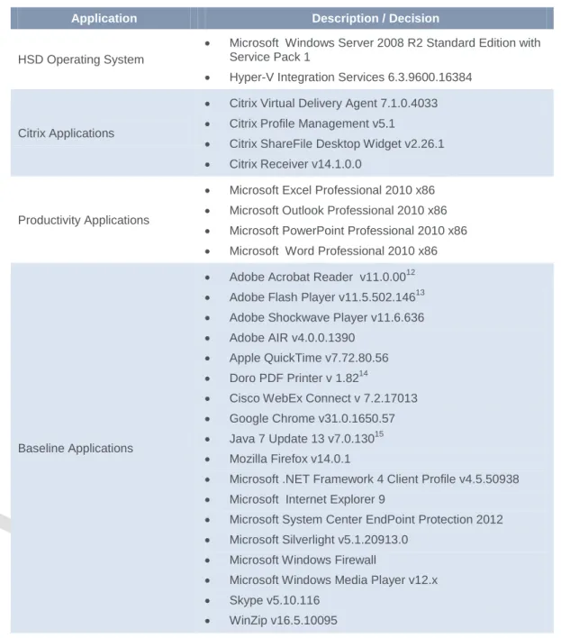
The Citrix Validated Solution was tested utilising application sets representative of enterprise-level Standard Operating Environment (‘SOE’) applications. These applications are pre-installed or embedded as part of the “master image”.
Note a number of pre-requisite applications we’re required to drive the Login VSI scalability testing. The following table represents the application set that formed the desktop workload profile:
Hosted Shared Desktop Application Set
Application Description / Decision
HSD Operating System
Microsoft Windows Server 2008 R2 Standard Edition with Service Pack 1
Hyper-V Integration Services 6.3.9600.16384
Citrix Applications
Citrix Virtual Delivery Agent 7.1.0.4033
Citrix Profile Management v5.1
Citrix ShareFile Desktop Widget v2.26.1
Citrix Receiver v14.1.0.0
Productivity Applications
Microsoft Excel Professional 2010 x86
Microsoft Outlook Professional 2010 x86
Microsoft PowerPoint Professional 2010 x86
Microsoft Word Professional 2010 x86
Baseline Applications
Adobe Acrobat Reader v11.0.0012
Adobe Flash Player v11.5.502.14613
Adobe Shockwave Player v11.6.636
Adobe AIR v4.0.0.1390
Apple QuickTime v7.72.80.56
Doro PDF Printer v 1.8214
Cisco WebEx Connect v 7.2.17013
Google Chrome v31.0.1650.57
Java 7 Update 13 v7.0.13015
Mozilla Firefox v14.0.1
Microsoft .NET Framework 4 Client Profile v4.5.50938
Microsoft Internet Explorer 9
Microsoft System Center EndPoint Protection 2012
Microsoft Silverlight v5.1.20913.0
Microsoft Windows Firewall
Microsoft Windows Media Player v12.x
Skype v5.10.116
WinZip v16.5.10095
Table 23: HSD Application Set
12
Application required and deployed by Login VSI for scalability testing.
13
Application required and deployed by Login VSI for scalability testing.
14
Application required and deployed by Login VSI for scalability testing.
15
32
Hosted Virtual Desktop Application Set
Application Description / Decision
HVD Operating System Microsoft Windows 7 Professional Service Pack 1 x64
Hyper-V Integration Services 6.3.9600.16384
Citrix Applications
Citrix Virtual Delivery Agent 7.1.0.4033
Citrix Profile Management v5.1
Citrix ShareFile Desktop Widget v2.26.1
Citrix Receiver v14.1.0.0
Productivity Applications
Microsoft Excel Professional 2010 x86
Microsoft Outlook Professional 2010 x86
Microsoft PowerPoint Professional 2010 x86
Microsoft Word Professional 2010 x86
Baseline Applications
Adobe Acrobat Reader v11.0.0016
Adobe Flash Player v11.5.502.14617
Adobe Shockwave Player v11.6.636
Adobe AIR v4.0.0.1390
Apple QuickTime v7.72.80.56
Doro PDF Printer v 1.8218
Cisco WebEx Connect v 7.2.17013
Google Chrome v31.0.1650.57
Java 7 Update 13 v7.0.13019
Mozilla Firefox v14.0.1
Microsoft .NET Framework 4 Client Profile v4.5.50938
Microsoft Internet Explorer 9
Microsoft System Center EndPoint Protection 2012
Microsoft Silverlight v5.1.20913.0
Microsoft Windows Firewall
Microsoft Windows Media Player v12.x
Skype v5.10.116
WinZip v16.5.10095
Table 24: HVD Application Set
16
Application required and deployed by Login VSI for scalability testing.
17
Application required and deployed by Login VSI for scalability testing.
18
Application required and deployed by Login VSI for scalability testing.
19
33
Master Image
The master image is defined by an operating system, image size and a set of applications that are installed into the image.
Configuration settings will be applied directly to the master image and using Active Directory Group Policies where appropriate, ensuring consistent deployment and optimisation. Antivirus will be included with specific configurations as documented within this article: http://support.citrix.com/article/CTX127030
Hosted Shared Desktop Workload
Figure 16. HSD Workload Configuration
Based on the system testing carried out, the following table describes the most optimal configuration for HSD on Windows Sever 2008 R2 RDS workloads for user/session density.
Server Node # of VMs
per Node RAM vCPU
User Sessions
per VM
Total # of Users per Node20
Shared Infrastructure
& Desktop Node 5 16 GB 8 ~28 150 Desktop Node 6 16 GB 8 ~30 180
Table 25: HSD Virtual Machine Specification and Sizing Estimates
Virtual Machine Specifications Description / Decision
Storage System Drive: (Difference Disk) C:\ = 100GB
Pagefile Fixed 16GB (1 x Assigned Memory) Network Interface Single - Synthetic NIC for production traffic Memory 16GB Dynamic Memory not used
vCPU 8
Operating System Microsoft Windows Server 2008 R2 Standard Edition with Service Pack 1
Storage IO Profile per User Logon – 30 reads / 30 writes
20
34
Virtual Machine Specifications Description / Decision
Logoff – 10 reads / 30 writes Steady State – 1 read / 2 writes Storage IO Profile per Node (assume
180 HSDs running on the Node) Boot Storm – 2,500 reads / 500 writes
Table 26: HSD-Windows Server 2008 R2 RDS Virtual Machine Specification
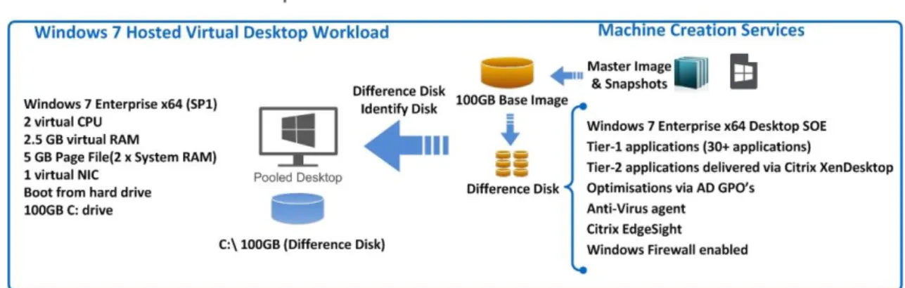
Hosted Virtual Desktop Workload
Figure 17. Hosted Virtual Desktop Workload Configuration
Based on the system testing carried out, the following table describes the most optimal configuration for the Windows 7 workload for user/VM density:
Server Node # of VMs per
Node RAM vCPU
Total # of Users per Node21
Shared Infrastructure &
Desktop Node
100 2.5GB 2 100 Desktop Node 150 2.5GB 2 150
Table 27: HVD Virtual Machine Specification and Sizing Estimates
Virtual Machine Specifications Description / Decision
Storage System Drive: (Difference Disk) C:\ = 100GB
Pagefile 5GB (2 x Assigned Memory)
Network Interface Single - Synthetic NIC for production traffic
Memory 2.5GB Dynamic Memory enabled. Please refer to the
VMM section for further details vCPU 2
Operating System Microsoft Windows 7 Professional Service Pack 1 x64
21
35
Virtual Machine Specifications Description / Decision
Storage IO Profile per User
Logon – 150 reads / 45 writes Logoff – 60 reads / 35 writes Steady State – 4 read / 4 writes Storage IO Profile per Node (assume
150 HVDs running on the Node) Boot Storm – 10,000 reads / 1,600 writes
Table 28: HVD-Windows 7 Virtual Machine Specification
The virtual workloads are deployed using Citrix Machine Creation Services (MCS). MCS utilises the hypervisor APIs to deploy, stop start and delete virtual machines. A master image must first be deployed that contains the virtual machine resource requirements such as vCPU and memory. Applications and agents are installed in the master image that is required for the virtual machine deployment. Finally a snapshot is created within the hypervisor that will be used for the Catalogs base image deployment by MCS.
A XenDesktop Catalog is deployed based on this master image snapshot, for each virtual machine created within this Catalog MCS will create the following virtual disks:
Identity disk. An Identity disk which is used to provide each VM with a unique identity. Difference disk. A Difference disk which is used by each VM to store writes that are
typically made to the system.
Pooled stateless (non-persistent) desktops using MCS are unique in that the differencing disk is deleted and recreated at each boot ensuring that the VM is set back to a clean state after each reboot effectively deleting any newly written or modified data. In this scenario, certain
processes are no longer efficient and optimisation of this image is required. Optimisations and configurations can be applied at several levels:
Workload Configuration master image. Changes are made directly to the master image. These changes are considered inappropriate to be applied using GPOs or are required settings prior to MCS generalising the image. The master image is then shut down and a snapshot taken by the hypervisor. MCS is then used to deploy the master image (from the snapshot) either to create a new or update an existing XenDesktop Catalog.
Workload Configuration GPO. These changes are applied via Active Directory GPO and are considered baseline configurations required in almost all instances. Typical use cases for this GPO are Event log redirection, Citrix Profile Management
configuration and target device optimisations. In addition this GPO may have Loopback processing enabled allowing user based settings to be applied to the virtual desktop Organisation Unit level.
User Optimisations GPO. This Active Directory GPO contains optimisations for the user within the virtual desktop environment. User optimisations cannot typically be deployed as part of the master image and are considered independent. Typical use cases for this GPO are folder redirection and user specific optimisations.
36
Control Layer Design
The control layer provides the design decisions for the underlying infrastructure supporting the virtual desktop layer.
The Control Layer design is unique per data centre and subdivided into the following components: Infrastructure
Desktop Delivery Controllers (XenDesktop) Image Controllers (Machine Creation Services) Access Controllers (StoreFront)
37
Infrastructure
The infrastructure for this Citrix Validated Solution provides a set of common components, namely a database, license server, Active Directory and network components. File Services are covered in a separate section.
Database
Citrix XenDesktop and Virtual Machine Manager require databases to store configuration metadata and statistical information. A highly available database platform utilising Microsoft SQL Server is required as the database platform. The database platform must be designed in such a way as to provide adequate resources and availability to support the environment.
Category Design Decision
SQL Version Microsoft SQL Server 2012 Standard Edition SP1 (used at the time of testing)
Please refer to the following article for a list of Citrix supported database platforms:
http://support.citrix.com/servlet/KbServlet/download/18493-102-706969/Database%20Chart.pdf
Redundancy XenDesktop:
Mirrored: Synchronous mirroring
Please refer to the following article for database fault tolerance:
http://support.citrix.com/proddocs/topic/xendesktop-71/cds-plan-high-avail-rho.html
Microsoft VMM:
Please refer to the following article for further details:
http://technet.microsoft.com/en-us/library/gg610574.aspx
http://technet.microsoft.com/en-us/sqlserver/gg490638.aspx Number of Servers 222
Server O/S Microsoft Windows Server 2012 R2 Standard Edition CPU Allocation 2 vCPU (Example)
RAM Allocation 8GB (Example) Storage Allocation C:\ 100
D:\ 100 (Databases) (Example)
Table 29: Database Summary
This document provides sample sizing guidelines and the licensing requirements for the actual databases used in this Citrix Validated Solution, however does not attempt to provide design guidelines for Microsoft SQL Server. The design and implementation for a highly available Microsoft SQL Server platform is required although considered out of scope for this design document.
22
Assumes SQL Server is licensed as a 2 VCPU (v-cores) virtual machine with MS Software Assurance. SQL Server license requires minimum of 4 core licenses. Active-Passive SQL Server deployment means no additional licenses are required for secondary passive SQL Server. Refer to http://www.microsoft.com/licensing/about-licensing/sql2014.aspx
38
Licensing
The licensing component (Microsoft and Citrix) grants each user access to the environment, as long as enough licenses are available. In addition, the type of license can also grant/deny different levels of functionality.
The key design decisions for the license server are as follows:
Category Citrix Microsoft
License Server Version 11.11.1 DECISION POINT
Redundancy Built in Grace period and Hypervisor
DECISION POINT
Number of Servers 1 DECISION POINT
Server Name(s) DECISION POINT DECISION POINT
Server O/S Microsoft Windows Server 2012 R2 Standard Edition
DECISION POINT
CPU Allocation 2 DECISION POINT
RAM Allocation 4GB DECISION POINT
Storage Allocation C:\ 100GB DECISION POINT
License Type DECISION POINT DECISION POINT
Table 30: Licensing Summary
Redundancy. Redundancy is built into the Citrix License service via the built-in 30 day grace period. Service redundancy can be further facilitated by the underlying hypervisor; therefore a single server is recommended.
Active Directory Integration. The License server machine object will be logical located in a dedicated Organisational Unit with specific Group Policy Objects applied as appropriate to the role please refer to the Active Directory Section for more details.
39
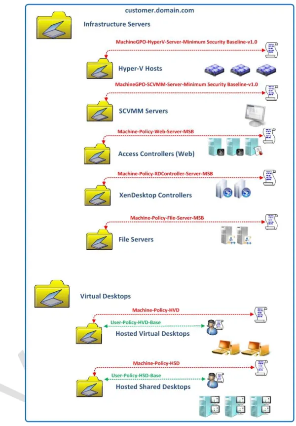
Active Directory
This Citrix Validated Solution has a requirement to use Microsoft Active Directory Domain Services and as such, it is an assumption that such an environment already exists within the customer’s environment. The decisions discussed below describe requirements from the existing Active Directory in the form of Organisational Units and Group Policy Objects. Supplementary requirements must also be met, to ensure sufficient capacity from
authenticating Domain Controllers can handle any additional requirements or load placed on the system by adding further Users, Groups, machine Objects and policy processing load. DECISION POINT
Category Decision / Description
Group Policy Application Recommended:23
Each infrastructure server role will have a minimum security baseline applied (MSB) via GPO
All RDS workloads will have a minimum security baseline applied (MSB) via GPO
Windows 7 workloads will have a minimum security baseline applied (MSB) via GPO
RDS workloads will have a Machine GPO applied specific to their application delivery requirements. This GPO may have Loopback mode enabled to apply user based settings at the RDS workload OU level
Windows 7 workloads will have a Machine GPO applied specific to their application delivery requirements. This GPO may have Loopback mode enabled to apply user based settings at the machine workload OU level
User based policies may be applied at the user or machine level using the loopback mode
Infrastructure servers such as Hyper-V hosts will be deployed in relevant OUs and MSBs applied appropriate to their role.
Table 31: Active Directory Requirements
The recommended Group Policy and Organisational Unit strategy applied to this Citrix Validated Solution is based on deploying Group Policy Objects in a functional approach, e.g. settings are applied based on service, security or other functional role criteria. This ensures that security settings targeted for specific role services such as IIS, SQL etc. receive only their relevant configurations.
It is anticipated that the final design will be customer dependant and based on other factors such as role based administration and other typical elements outside the scope of this document. Refer to the Appendix: DECISION POINT
23 Reference to Minimum Security Baselines in the form of GPOs will be the customer’s responsibility. GPOs
40
41
Delivery Controllers (XenDesktop)
Delivery Controllers, also known as XenDesktop controllers (Image Controllers), are responsible for enumerating, allocating, assigning and maintaining virtualised desktops and applications. Delivery Controllers within a single data centre are grouped together into a XenDesktop site, which functions as a single administrative entity.
This Citrix Validated Solution specifically defines the Hosted Virtual Desktop and Hosted Shared Desktop FlexCast delivery models. From a XenDesktop perspective each desktop type will belong to a Catalog configured specifically for that FlexCast delivery type and associated with a Hyper-V host’s Local Storage.
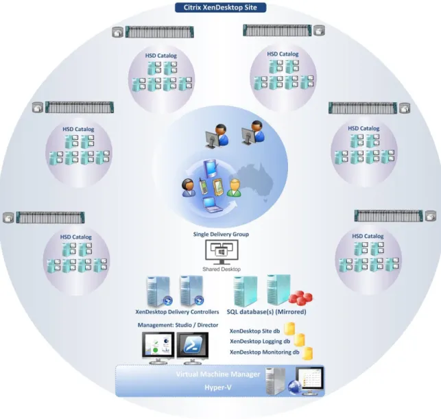
The Illustration below identifies the components of the XenDesktop Site describing the Hosted Shared Desktop Catalogs deployed as part of the Citrix Validated Solution:
42
The Illustration below identifies the components of the XenDesktop Site describing the Hosted Virtual Desktop Catalogs deployed as part of the Citrix Validated Solution:
43
XenDesktop Site
Based on the validation testing and resiliency requirements of this Citrix Validated Solution the following table describes the XenDesktop site design parameters.
Category Design Decision
Version, Edition Citrix XenDesktop 7.1 Sites per Data
Center
The Citrix Validated Solution is designed as a single Site for a single data centre
Site Name(s) DECISION POINT
Server O/S Microsoft Windows Server 2012 R2 Standard Edition Controllers per Site 2 (Single Site Deployment)
Each Delivery Controller also functions as an MCS Image Controller XenDesktop
Administrators
DECISION POINT
Site Database Refer to the Section Databases
Configuration database
Refer to the Section Databases
Monitoring Database
Refer to the Section Databases
Catalogs A Catalog will be created for each Hyper-V host and aligned with the local storage presented by each host.
For 1,000 HSD users:
6 Catalogs are required (1 per Cisco C240 M3 SFF Server) For 1,000 HVD users:
8 Catalogs are required (1 per Cisco C240 M3 SFF Server)
Delivery Groups A single Delivery Group will be created for each virtual desktop type. The Delivery Group will host desktops from multiple Catalogs of the same type Citrix Policies Refer to the Appendix for further details
Hypervisor integration
System Center Virtual Machine Manager 2012 R2
VMM console installed on Delivery Controller servers Host Connections A single Host Connection will be created for each Hyper-V Host
Type: Microsoft System Center Virtual Machine Manager
Name: <Based on host server name Refer to the Appendix for further details
Address: Refer to the Appendix for further details
44
For XenDesktop Catalogs hosting server operating systems (also known as XenApp), users are load balanced based on resource availability at user logon. Load management includes Load Throttling, which ensures that a new server brought into service does not initially receive a disproportional number of connections. This Citrix Validated Solution recommends
implementing a “Custom” load evaluator with the following minimum parameters:
Load Evaluator Parameter Setting Applied To
Custom
CPU Utilization 85% Full, 10% No load
All servers Memory Usage 80% Full, 10% No load
Server User Load 30 Full
Table 33: XenApp Load Evaluator Details
XenDesktop Site. The XenDesktop site will consist of two virtualised Desktop Delivery
Controllers. Each Delivery Controller virtual machine will always be separated on one of the two shared infrastructure/virtual desktop hypervisor hosts. This will ensure resiliency of the
environment. Loss of a single infrastructure host or Delivery Controller will not interrupt normal user operations.
A host connection will be defined that establishes a connection to the VMM server and each of the Hyper-V standalone host. A specified service account will be used for this purpose refer to the Appendix for further details
Catalogs. For each virtual desktop type a Catalog will be created per physical server host defining the Catalog Base image for that server’s local storage. The Catalogs will then be aggregated into a single unified Delivery Group for the presentation to users via StoreFront. Within the host connection, a storage connection and network related resource will be specified for each host. E.g.
Server Name Local Storage
HVD-VLAN_1 and HVD-VLAN_2
45
Desktop Presentation. From the corporate LAN/WAN, StoreFront will be utilised for the presentation of desktops to end users.
Desktop Director and EdgeSight. Citrix EdgeSight is now integrated into a single console within Desktop Director, with its feature set enabled based on Citrix Licensing. The monitoring database used by EdgeSight will be separated from the site and logging database to allow appropriate management and scalability of the database. Historical data retention is available for 90 days by default with Platinum licensing. Administrators can select specific views delegating permissions concisely for helpdesk staff, allowing easy troubleshooting and faster resolution of problems. Citrix EdgeSight will provide the following key components:
Performance Management. EdgeSight provides the historical retention with reporting capabilities.
Real Time. Director provides the real time views for support staff to further investigate any reported problems.
Active Directory Integration. Each Machine object will be logical located in a dedicated Organisational Unit with specific Group Policy Objects applied as appropriate to the role please refer to the Active Directory Section for more details.
46
Image Controllers (Machine Creation Services)
Image Controllers are responsible for providing the actual desktop image for Pooled desktops. Pooled desktop images are created with the built-in Citrix Machine Creation Services (MCS) functionality on each Desktop Controller. MCS is a collection of services that work together to create virtual servers and desktops from a master image on demand, optimising storage utilisation and providing a pristine virtual machine to users every time they log on. Machine Creation Services is fully integrated and administrated in Citrix Studio and does not require additional servers. There are virtually no moving parts within MCS, as all operations are executed directly from the Citrix Delivery Controllers
Each pooled desktop has one difference disk and one identity disk. The difference disk is used to capture any changes made to the master image while the identity disk stores machine identification information.
The key design decisions for the Image (Desktop Delivery) controllers are as follows:
Category Description
Preferred Imaging Solution
Machine Creation Services
MCS Storage Type Hyper-V Local Storage, provided by Windows Storage Space Tiers. Note. To replicate and deploy the master image across the hypervisor nodes, the master image (VM template) will live migrated and copied locally. Refer to the CVS Deployment Guide for more information. Server Names Desktop Delivery Controllers
DECISION POINT
Server O/S Microsoft Windows Server 2012 R2 Standard Edition CPU Allocation 2 vCPU
RAM Allocation 8GB Storage Allocation C:\ 100GB
47
Access Controllers (StoreFront)
Access Controllers are responsible for user authentication and connectivity to the environment. They provide the framework allowing users to access the environment from any device and any location.
All users, regardless of being internal or external will need to gain access to a list of their virtualised resources via StoreFront.
The key design decisions for StoreFront controllers are as follows:
Category Design Decision
Server O/S Microsoft Windows Server 2012 R2 Standard Edition Server per Site 2
Server Name(s) DECISION POINT
CPU Allocation 2 vCPU RAM Allocation 4 GB Storage Allocation C:\ 100GB Access Method Internal
Load Balancing DNS Round Robin
Table 35: StoreFront Site Summary
Two virtualised StoreFront servers will be deployed. Each StoreFront virtual machine will always be separated on one of the two shared infrastructure/virtual desktop hypervisor hosts. This will ensure resiliency of the environment. Loss of a single infrastructure host or StoreFront server will not interrupt normal user operations.
The Citrix StoreFront servers may be load balanced using DNS round-robin. Optionally, Citrix StoreFront servers may be load balanced using Citrix NetScaler appliances configured in high availability mode (HA). Citrix specific service monitors can then be utilised to monitor the health of the StoreFront services to ensure intelligent load balancing decisions are performed increasing service availability.
Active Directory Integration. Each Machine object will be logical located in a dedicated Organisational Unit with specific Group Policy Objects applied as appropriate to the role please refer to the Active Directory Section for more details.
48
Hypervisor Layer
Microsoft Hyper-V Server® 2012 R2 Edition will be deployed to each Cisco C240 M3 SFF server and configured as a standalone host. Hyper-V will provide the hypervisor hosting platform to the virtualised desktop and infrastructure server instances. Microsoft System Center Virtual Machine Manager (VMM) will be leveraged to provide the virtual machine operations and management interface to Hyper-V. VMM will also provide the integration interface between Citrix XenDesktop and the underlying hypervisor within the XenDesktop host connection.
Hyper-V Overview
The Illustration below depicts the physical components logically connected between a single Cisco C240 M3 SFF Server, the hypervisor, and associated switching infrastructure:
Network. 4 x 1 Gbps On-board Ethernet Adapter.
Management. 1 x 1 Gbps On-board Management Adapter for CIMC (Cisco Integrated Management Controller).
Network Teaming. 2 x Network Teams created consisting of 2 x Physical Network adapters (pNIC).
o Team A. Management and Live Migration (pNIC 1 + pNIC2).
o Team B. VM Data traffic (pNIC3 + pNIC4).
HSD Hyper-V Host
49
HVD Hyper-V Host
Figure 24. HVD Hyper-V Host Logical View
Hyper-V Hardware Details
Category Decision / Description
Hardware Refer to the section: Cisco C240 M3 SFF Rack Mounted Server(s)
Table 36: Hyper-V Hardware Details
Hyper-V General Details
Live Migration. The ability to live migrate virtual machines across standalone hosts with local storage (Shared nothing migration) will be enabled, allowing scheduled down time for maintenance tasks to occur on individual hosts. The following are required parameters for Live Migration:
Live Migrations will be limited to the default of 2 simultaneous migrations. The Live Migration IP subnet will be defined for migration traffic.
Kerberos authentication protocol will be enabled for migrations. Compression will be enabled.
It is recommended that QoS is configured for the Live Migration network to ensure the available bandwidth consumed by migration traffic does not interfere with the management network, since the underlying physical network is shared.