Exergy Calculation
This chapter is intended to give the user a better knowledge of exergy calculations in Cycle-Tempo. Exergy is not an absolute quantity but a relative one. Therefore, to say something about it, it must be known to which exergy level the calculation must be compared with. In Cycle-Tempo the exergy calculations are based on the chosen environment conditions. So, it is necessary to set the environment conditions in Cycle-Tempo or else an exergy calculation will not be made. Throughout this chapter the environment is chosen to be like that of Baehr at 25o C.
In subsection 1.1 the definition of exergy will be given and in subsection 1.2 some example calculations will be discussed.
3.1
Definition of exergy
According to van Lier [1] the quantity exergy is defined as:
The amount of work which can be received from an energy carrier in a process that:
• is reversible.
• takes place in an open system with stationary flow.
• exchanges heat only with the environment.
• is in balance with the environment at the end of the process.
In balance with the environment means that the thermal mechanical and the chemical exergy of the energy carrier is equal to that of the environment. The thermal mechanical exergy is the amount of energy that is released when the energy carrier is expanded (or compressed) to the environment pressure and cooled (or heated) to the environment temperature.
The chemical exergy of the energy carrier is the amount of energy released if the components in the energy carrier through chemical reactions are transferred to the environment components and diffundated into this environment.
3.2
Exergy calculations
In order to gain a better understanding of the definition stated in section 1.1 in this subsection some simple calculations with exergy will be shown. In subsection 1.2.1 the example will show a thermal mechanical exergy calculation whit a gas mixture equal to that of the environment. In subsection 1.2.2 an exergy calculation will be shown of CO2, a component that also exists in environment conditions. And in the last subsection (1.2.3.) a combined thermal mechanical and chemical calculation is done of a component that can be formed by chemical reactions from environmentcomponents.
3.2.1. Exergy of environment air
In this example environment air with a pressure of 5 bars and a temperature of 350˚ C. is expanded and cooled down to the environment conditions of Baehr (25˚ C). Because the used components are equal to the conditions of Baehr no chemical reaction is needed to achieve the “environment like Baehr”. Therefore the chemical exergy is zero. In figure 1, the Cycle-Tempo plot is shown and in tables 1 and 2 some additional information is given.
Please keep in mind that this gas is not standard air in Cycle-Tempo but specifically adjusted gas that equals the environment air.
Figure 1: Environment air
Table 1: Energy and exergy flows for environment air
Pipe Total Energy flow
Therm.Mec. Energy flow
Chemical energy
Total Exergy flow
Therm.Mec. Exergy flow
Chemical exergy
no. [kW] [kW] [kW] [kW] [kW] [kW]
1 3869.82 3869.82 0.00 2487.21 2487.21 0.00
2 479.65 479.65 0.00 0.14 0.00 0.14
Table 2: Data for pipes with environment air
Pipe Mass
flow
Mole flow
Volume flow
Pressure Tempera ture
Enthalpy Entropy Exergy
no. [kg/s] [kmol/s] [m3/s] [bar] [°C] [kJ/kg] [kJ/kg.K] [kJ/kg]
1 10.000 0.349 3.6202 5.000 350.00 71.30 7.2748 248.72 2 10.000 0.349 8.5470 1.013 25.00 -267.71 6.9719 0.01
With the information given in the tables an exergy calculation can be made. The thermal mechanical exergy can be calculated with:
(
)
*
(
)}
{
*
0 0 0,tm m
h
h
T
S
S
ExEx
=
Φ
=
Φ
−
−
−
Φ
[kW])}
9719
.
6
2748
.
7
(
*
16
.
298
)
71
.
267
)
(
30
.
71
{(
*
10
21
.
2487
=
−
−
−
−
Because the conditions in pipe 2 are equal to that of the environment of Baehr, the values of which the exergy calculation is related to, these values can be used in the formula for h0and So , respectively.
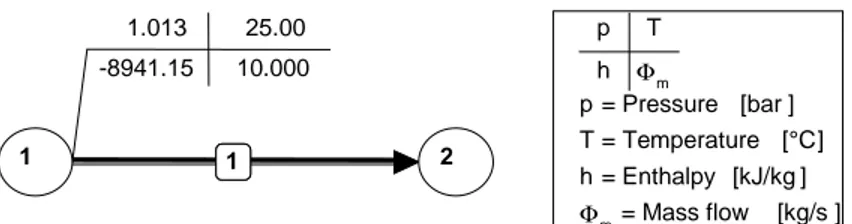
3.2.2. Exergy of CO
2In this example, the chemical exergy of one component that also consists in the environment will be calculated. In this case, CO2 gas is chosen. First the plots and the tables are given as shown.
1.013 25.00 -267.71 10.000
2 2
5.000 350.00 71.30 10.000
1
1 3
2 1
p T
h Φm
p = Pressure [bar] T = Temperature [°C]
Φm = Mass flow [kg/s]
Environment like Baehr
Figure 2: CO2 gas
Table 3: Energy and exergy flows CO2
Pipe Total Energy flow
Therm.Mec. Energy flow
Chemical energy
Total Exergy flow
Therm.Mec. Exergy flow
Chemical exergy
no. [kW] [kW] [kW] [kW] [kW] [kW]
1 89411.53 89411.53 0.00 4569.04 0.00 4569.04
Table 4: Data for CO2
Pipe Mass flow
Mole flow
Volume flow
Pressure Tempera-ture
Enthalpy Entropy Exergy
no. [kg/s] [kmol/s] [m3/s] [bar] [°C] [kJ/kg] [kJ/kg.K] [kJ/kg]
1 10.000 0.227 5.5590 1.013 25.00 -8941.15 4.8556 456.90 Although the temperature and the pressure are equal to that of the environment, the CO2 does contain thermal mechanical exergy. This might look strange but can easily be explained if notice is taken of the fact that the pressure of the CO2 gas is not equal to the partial pressure of the CO2 in the environment air. Therefore, in order to calculate the exergy of the CO2 gas it now must be expanded to the partial pressure. This calculation will be shown in the following:
The partial pressure of the CO2 gas in the environment according to Baehr is 0.03%. The equation for the specific expansion work is:
ö
ç
ç
è
æ
=
j j
mol
p
p
T
R
n
w
*
*
0*
ln
0 [kJ/kmol]ö
ççè
æ
=
0 0 3
*
%
03
.
0
ln
*
16
.
298
*
314
.
8
*
1
10
*
01
.
20
p
p
At which nj represents the mole fraction of the specific element. In this particular case this value is 1 because the gas only exists of CO2.
Now this specific value has to be transferred into the total expansion work to compare it with the value given in table 3.
mol mole
ansion
w
W
exp=
Φ
*
[kW]3
10
*
01
.
20
*
227
.
0
04
.
4564
=
Environment like Baehr 1.013 25.00
-8941.15 10.000
1
1 2
1
p T h Φm
p = Pressure [bar ] T = Temperature [°C] h = Enthalpy [kJ/kg ]
3.2.3. Exergy of solid carbon
In this subsection, the exergy of sold carbon will be calculated. Carbon does not exist in environment conditions but can be formed through chemical reactions with other components. As explained in subsection 1.1 the chemical exergy is the amount of energy released if the component through chemical reactions is transferred to the environment components and diffundated into this environment. As done in the previous subsections first the plots and tables are shown.
Figure 3: Solid carbon
Table 5: Energy and exergy flows for solid carbon
Pipe Total Energy
flow
Therm.Mec. Energy flow
Chemical energy
Total Exergy flow
Therm.Mec. Exergy flow
Chemical exergy
no. [kW] [kW] [kW] [kW] [kW] [kW]
1 327615.31 2.38 327612.94 341800.72 0.00 341800.72
Table 6: Data for al pipes with solid carbon
Pipe Medium Mass flow
Mole flow
Volume flow
Pressure Temperature Enthalpy Entropy Exergy no. GASMIX [kg/s] [kmol/s] [m3/s] [bar] [°C] [kJ/kg] [kJ/kg.K] [kJ/kg]
1 10.000 0.833 20.369 1.013 25.00 0.24 0.4737 34180.07
The data in the following table is drawn from Baehr [2].
Table 7: Enthalpy and absolute entropy
0 298
h
s
2980 yfg[kJ/mol] [J/mol K] Mole %
C 0 5.740
-O2 0 205.03 20.30
CO2 -393.51 213.6 0.03
With the data in the tables above the calculation will be the following. The chemical reaction to change the carbon into environment component is:
p T h Φm
p = Pressure [bar] T = Temperature [°C] h = Enthalpy [kJ/kg]
Φm = Mass flow [kg/s]
Environment like Baehr 1.013 25.00
0.24 10.000
1
1 2
And the energy released when this reaction occurs is equal to:
(
0)
298 , 0 298 , 0 298 , 1
,
1
*
CO21
*
C1
*
O2 molrev
g
g
g
w
=
−
−
−
[kJ/mol](
)
(
)
{
0}
298 , 0 298 , 0 298 , 0 0 298 , 0 298 , 0 298 , 1
, CO2 C O2
*
CO2 C O2mol
rev
h
h
h
T
s
s
s
w
=
−
−
−
−
−
−
[kJ/mol](
)
(
)
31
,
393
.
51
0
0
298
*
213
.
6
5
.
740
205
.
03
*
10
−
−
−
−
−
−
−
−
=
mol revw
[kJ/mol]67
.
392
1 ,=
mol revw
The chemical reaction takes place at environment pressure. Therefore, the oxygen, which is reacting with the carbon, first must be compressed from its partial pressure to the environment pressure. Afterwards, when the reaction has finished the carbon dioxide must be expanded from the environment pressure to the partial pressure at which the carbon dioxide exists in environment conditions.
The (reversible) work necessary when the O2 is compressed from its partial pressure to environment pressure is:
ö
ç
ç
è
æ
−
=
j m j mol revp
p
T
R
n
w
,2*
*
0*
ln
0 [kJ/mol]ö
ççè
æ
−
=
− 0 0 3 2 ,*
2030
.
0
ln
*
298
*
10
*
3143
.
8
*
1
p
p
w
molrev [kJ/mol]95
.
3
2 ,=
−
mol revw
Moreover, the work released when the CO2 is expanded from environment pressure to partial pressure is:
ö
ççè
æ
−
=
0 0 3,
*
*
*
ln
p
p
T
R
n
w
j m jmol
rev [kJ/mol]
ö
ççè
æ
−
=
− 0 0 3 3 ,*
0003
.
0
ln
*
298
*
10
*
3143
.
8
*
1
p
p
w
revmol [kJ/mol]11
.
20
3 ,=
mol revw
Now, the exergy of the carbon can be calculated by adding the three calculations from above:
mol rev mol rev mol rev mol
C
w
w
w
ex
=
,1+
,2+
,3 [kJ/mol]83
.
408
95
.
3
11
.
20
67
.
392
+
−
=
=
mol C
ex
[kJ/mol]Or, m mole mol c c
ex
ex
Φ
Φ
=
*
[kJ/kg]54
.
34055
10
10
*
833
.
0
*
83
.
408
3=
=
Cc m
c
ex
Ex
=
Φ
*
[kW]54
.
34055
*
10
4
.
340555
=
[kW]According to table 5 the total exergy flow is 341800.72 kW which differs less than 0.04%. This difference can be assigned to rounding off in the calculation
[1]: Thermodynamische processen in de centrale en de mogelijkheden tot het verbeteren van deze processen, J.J.C. van Lier; Technische Universiteit Delft
[2]: Thermodynamik, Baehr, 3 aufl.
Input summary of the air
Description
System data: NAPP=3, NLIN=2, NCYCLE=1, NPRINT=4
Apparatus: NO=1, TYPE=10, APNAME='Sink/Source', POUT= 5, TOUT= 350, DELM= -10
Apparatus: NO=2, TYPE=10, APNAME='Heat Sink', SUBTYP=1, POUT= 1.01325, TOUT= 25
Apparatus: NO=3, TYPE=10, APNAME='Sink/Source'
Medium: Pipe No = 1, Type = 'GASMIX'
Specie = AR CO2 H2O N2 O2
Mole % = 0.9 0.03 3.12 75.65 20.3
Environment: Default environment of Baehr Environment composition:
Specie = AR CO2 H2O N2 O2
Mole % = 0.9 0.03 3.12 75.65 20.3
Environment pressure: 1.01325 bar Environment temperature: 25 °C Heating values calculated at 1 atm, 25 °C
Input summary of the CO2
Description
System data: NAPP=2, NLIN=1, NCYCLE=1, NPRINT=4
Apparatus: NO=1, TYPE=10, APNAME='Sink/Source', POUT= 1.01325, TOUT= 25, DELM= -10
Apparatus: NO=2, TYPE=10, APNAME='Sink/Source'
Medium: Pipe No = 1, Type = 'GASMIX'
Specie = CO2
Mole % = 100
Environment: Default environment of Baehr Environment composition:
Specie = AR CO2 H2O N2 O2
Mole % = 0.9 0.03 3.12 75.65 20.3
Environment pressure: 1.01325 bar Environment temperature: 25 °C Heating values calculated at 1 atm, 25 °C