Generic Editing of Visual Languages based on SVG standard
Tiago Lopes Telecken,
José Valdeni de Lima,
Universidade Federal do Rio Grande do Sul, Porto Alegre ,RS, Brazil
{telecken,valden}@inf.ufrgs.br
Abstract
Generic editing of visual languages can become easier with a common exchange format for graph transformation based on XML. In this sense, many XML languages (such as GXL, XGMML and GraphML) were developed to represent visual languages as a graph. These languages are compatible with XML technology and are interoperable with a great number of state of the art documentation and graphic technologies. We propose a common exchange format for graph transformation based on SVG, the GEVS XML Language. This proposal is completed with a visual language (GEVS Visual Language) and a meta model (GEVS Meta Model). The objective of the proposed solution is a greater accessibility and interoperability.
1. Introduction
Generic editing of visual languages (for instance, UML diagrams) can become easier with a common exchange format for graph transformation based on XML. In this sense, many XML languages (such as GXL, XGMML and GraphML) were developed to represent visual languages as a graph [4][18][3]. These languages present a modular approach, are compatible with XML technology [13] .
In this context, we propose the GEVS project (Generic Editing of Visual languages based on SVG standard). More specifically, in this paper we present a common exchange format for graph transformation based on XML: the GEVS XML Language. This proposal is completed with a visual language (GEVS Visual Language) and a Meta model (GEVS Meta Model).
The objective is provide a language more accessible, more interoperable, and maintains characteristics like modularity and adaptability found in GXL, GraphML and XGMML languages.
A document is accessible if it can be equally understood by its targeted audience regardless of the device used to access it [15]. With a greater accessibility, the document processing (for automatic
systems) and interpretation (for humans) becomes easier. The SVG has a strong industry/academic support and can give to the user a textual and graphical vision of documents[12]. Such SVG characteristics are explored in GEVS project to give a greater accessibility to the proposed exchange document format.
In the thesis context, this proposal aiming to simplify the preliminary results of the first year of PhD course studies, therefore this is a first step toward a more concise thesis definition.
2. Concepts of Visual Languages
Foremostly, three important terms are briefly presented: visual language, visual phrase and visual communication object.
According to Lakin [6], a visual language is a set of spatial arrangements of textual-graphic symbols with a semantic interpretation that is used in carrying out communicative actions in the world.
Additionally, Lakin [6] affirms that a visual phrase
is a set of textual-graphic symbols whose syntax and semantic is defined by a visual language.
A visual communication object, moreover,is a set formed by a visual phrase and additional data structures that complement the syntax and semantic of the visual phrase.
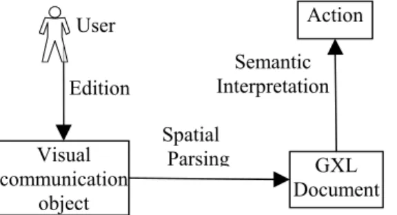
Three processes are needed to edit and interpret a visual communication object [2][6]: edition, spatial parsing and semantic interpretation.
In the editing process, the user inserts a visual communication object through a Graphical User Interface (GUI). Usually the visual phrase is inserted by the manipulation of a drawing and the additional data structures are added by fill-forms and menus interfaces.
The spatial parsing process is the process of recovering the underlying syntactic structure of a visual communication object from its spatial arrangement and additional data structures [2][6]. The result of the spatial parsing is a data structure whose syntax is defined by an Abstract Syntax Model (ASM) [2]. The data structure can either be
immediately processed by the semantic interpretation process or stored as a document, obeying an ASM
representation for future semantic interpretations.
Semantic interpretation process is the semantic processing of a visual communication object. The result of a semantic interpretation is an appropriate action, which might include a translation to some other text-graphic language, a support for agile manual manipulation of objects, or the execution of an instruction [6].
Figure 1 shows the relationships between the presented processes.
Figure 1. Processes
The focus of this article is the edition and interpretation of one type of visual languages: the
generic visual languages.
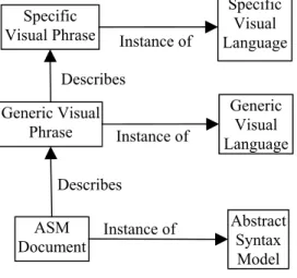
Figure 2. Languages and models
A generic visual language is a visual language whose generic visual phrases can abstract or describe visual phrases of others visual languages.
Figure 2 shows the relationships between instances of a specific visual language, a generic visual language and an abstract syntax model.
3. SVG
The Scalable Vector Graphics (SVG) [12] specification is an open standard that describes 2D graphics. This specification is an official recommendation of the World Wide Web Consortium (W3C).
In contrast to formats such as Joint Photographic Experts Group (JPEG) and Portable Network Graphics (PNG) that represent an image by specifying every pixel, the SVG represents an image through the use of geometric vectors associated with some attributes.
SVG allows combining geometric vectors with text and bitmap images such as JPEG, for example. The text, although being vector based, can be copied and manipulated as images.
Another important characteristic of SVG is the fact that it is an XML compatible language. Therefore, SVG is compatible with several technologies developed by the W3C, such as MathML, XHTML, XSLT, CSS, SMIL, DOM, XLink and Xpointer.
SVG is used in several domains including animation, user interface, web graphics, graphics interchange, print and hardcopy output and mobile applications. It has strong industry and academic support, SVG viewers are deployed to over 100 million desktops, cellphones, handsets, PDAs, and there is a broad range of support in many authoring tools [12 ].
4. Related Works
The SVG can be used to describe the graphic appearance of a visual language. However, visual languages do not contain only graphic data, but also semantic data. Graphic data defines the graphic appearance, whereas semantic data represents specific information about the domain area of a visual language.
To describe semantic data of visual languages, several specifications were created, each one developed for a specific domain. UXF (UML Exchange Format) [5], for example, describes instances of UML models. In this case, semantic data such as class diagram, classes, aggregations and associations are defined.
In some applications, a more adaptable and generic language becomes necessary. The PNML (Petri Net Markup Language)[7], for example, is a language that permits the description of several variants of Petri Net models. However, the growing necessity of adaptability and generalization motivate the development of languages that can describe any type of visual languages and not only a subset.
Spatial Parsing Semantic Interpretation visual communication object ASM Document Action Edition User Describes ASM Document Generic Visual Language Abstract Syntax Model Generic Visual Phrase Instance of Instance of Specific Visual Language Specific
Visual Phrase Instance of Describes
GraphML(Graph Markup Language)[3],
XGMML (eXtensible Graph Markup and Modeling Language)[18] and GXL (Graph eXchange Language)[4] are generic languages that describe visual languages instances as graphs. More precisely, they describe visual languages as directed graphs, undirected graphs, mixed graphs, hypergraphs, hierarchical graphs, graphical representations, references to external data and domain-specific semantic data [4]. Any visual language that can be described using these resources can be described with GraphML, XGMML and GXL languages. The approach of these generic languages is to describe a visual language instance as an abstract graph where the elements of the visual language are nodes, where some relationships between elements are edges, etc.
Applications that use specific languages, such as UXF (UML Exchange Format), for example, know the exact syntax and semantic of the model. However, the semantics of a visual language represented by a generic model is unknown for applications. Hence, additional information is needed to represent one specific visual language. Some types of additional information are: the specific graphical appearance of nodes and edges, and the constraints of the visual language. These constraints define the behavior of the graph. Some examples are: which node/edge types can be used, which relations can exist between nodes/edges of a given type and which attributes can be associated with nodes or edges.
The inclusion of this information can be done following a monolithic approach, where different types of information are described using the same language. In a modular approach, however, different types of information are described using different languages.
The GraphML does not describe constrains nor graphical appearance of nodes and edges. The GXL, on the other hand, describes some constraints but does not describe graphical appearance. And finally, the XGMML describes graphical appearance of nodes and edges but does not describe constrains. The approach of these languages is to consider that the information not described is defined (when this information is needed) by external documents or applications.
Several external languages are used with generic languages. SVG, for example, can be used to describe the graphical appearance of nodes and edges. DTD (Data Type Definition), XML Schema and XRL (eXchangeable Routing Language)[11] can be used to define constraints. XLink [16] can be used to define nesting or relationship. XSLT [17] can be used for translations. Besides these languages, external applications can be used to interpret or extract
information of documents according to the context or domain.
To illustrate the ideas presented in this section, two figures are shown below. They are applied to the GXL language, but could also be applied to GraphML and XGMML.
In Figure 3, an example of edition, spatial parsing and semantic interpretation process is shown. In this example the user edits a visual communication object that is parsed to a GXL document that subsequently is interpreted. The result of the interpretation is an action.
Figure 3. Translation, spatial parsing and semantic interpretation with GXL language
Instances of external languages, such as XSLT and XLink, can be used in the interpretation process to generate the appropriate actions.
In Figure 4 the models and instances relationships are shown where the specific visual language is a UML class diagram, the visual communication object is a visual phrase of GXL graphic representation plus additional data structures, and the ASM document is a GXL document.
Figure 4. Models and instances relationship
5. Generic Editing of Visual Languages
based on SVG standard (GEVS)
Instance of Describes GXL Document GXL Visual Language GXL Model GXL graphic representation + data Instance of Instance of UML Class Model UML class diagram Describes Spatial Parsing Semantic Interpretation GXL Document Action Visual communication object Edition User
Our proposal for storing and describing generically visual phrases contains: (i) a model to store visual phrases - GEVS Meta-Model; (ii) a visual language to describe/store the data defined in the meta model -GEVS Visual Language; and (iii) a XML Language to describe/store the data defined in the meta model -GEVS XML Language. The proposed XML Language and Visual Language are instances of the proposed Meta Model, shown in Figure 5.
Figure 5. GEVS languages relationships
The edition, parsing and interpretation of GEVS Visual Language is similar to GraphML, XGMML and GXL languages.
As it can be seen in Figure 6, the user edits a visual communication object that is parsed to a GEVS XML document and subsequently interpreted. The final result of the interpretation is an action.
Figure 6.Translation, spatial parsing and semantic interpretation with GEVS languages
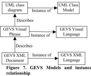
Figure 7 presents the relationships between models and instances where the specific visual language is a UML class diagram, the visual communication object is a GEVS visual phrase plus additional data structures, and the ASM document is a GEVS XML document.
Figure 7. GEVS Models and instances relationship
The following section presents the proposed languages in more details.
5.1. GEVS Meta Model
We apply a graph abstraction (such as GraphML, XGMML and GXL.) to define a generic data model that can maintain all information of a specific visual phrase. The following principles were adopted:
• Nodes and edges can represent a specific visual phrase.
• A graph can have many classes of nodes and many classes of edges.
• Nodes and edges can have attributes.
• Nodes and edges can have relationships with other nodes and edges.
Based in these principles we define the GEVS Meta Model that can be represented by the following UML class diagram:
Figure 8. Class diagram of GEVS Meta Model
In this model, node elements contain data about the nodes of a specific visual phrase. Edge elements contain data about the edges of a specific visual phrase. Edge and node elements contain attributes. Instance of Instance of GEVS Meta Model GEVS XML Language GEVS Visual Language Element Attributes Node Edge Class
Attribute AttributesGraphic AttributesSemantic 1 * Instance of Instance of Describes GEVS XML Document GEVS Visual Language GEVS XML Language GEVS Visual Phrase Instance of UML Class Model UML class diagram Describes Spatial Parsing Semantic Interpretation GEVS XML Document Action GEVS visual phrase + data structures User Edition
There are three types of attributes: (i) class attribute; (ii) graphic attributes and (iii) semantic attributes.
The class attribute contains the class of an element in a specific visual language.
Semantic attributes contain the domain specific
attributes of an element. These attributes are associated with a specific domain area described by specific visual language.
Graphic attributes, on the other hand, contain the graphic attributes of an element. These attributes define the generic graphical appearance and the graphical distribution of the elements according to the abstraction defined in the GEVS Visual Language.
The graphical distribution of elements in GEVS visual phrases contains information about the relationship among elements. The relationship information can be extracted from graphic attributes. Semantic attributes can contain additional information about relationships, when necessary.
5.2. GEVS Visual Language
To define a graphic abstraction for all specific visual languages we adopt the following principles.
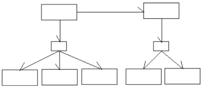
Visual languages can be represented by nodes and relationships between nodes. The relationships can be of 4 types: relationship by relative position, by nesting, by connection or by directed connection. GEVS Visual Language represents these relationships as is shown in figure 9.
Figure 9. Types of relationships
In this graphic abstraction, any visual language is described using two figures and its graphical distribution.
The rectangles abstract the appearance of specific visual phrase nodes. Lines abstract the appearance of specific visual phrase edges. A line can be an arrow and, thus, represent a directed edge.
Texts can be added to the graphical abstraction as commentaries. These texts can be visualized, but the interpreted information is only those that are associated with the rectangle and line figures. When a visual language has texts as an important part of visual phrases, these texts are represented by rectangles.
The relationship between elements can be obtained through the graphical distribution of nodes and edges. For example, if there is one line C between two rectangles (A and B), then there is one relationship between the nodes represented by rectangles A and B. The relationships are defined by spatial arrangements of graphic elements and by attributes of the elements A, B and C.
5.3. GEVS XML Language
The GEVS XML Language is a subset of SVG language. The syntax of the GEVS XML Language is a 100% valid SVG syntax. The difference is that we propose a new semantic to SVG elements and attributes.
The GEVS XML Language is formed by three SVG elements: the <svg> element, the <rect> element and the <polyline> element.
The <svg> element is the root element. It contains all others elements. The <rect> element represents the elements of type node. And the <polyline> element represents the elements of type edge. Directed edges are represented by polylines that describe an arrow. Simple edges, on the other hand, are represented by polylines that describe simple lines. Text commentaries can be added to the representation by using the SVG text element.
The graphic attributes of <rect> and <polyline> represent the graphic attributes of the GEVS Meta Model. The class attributes of <rect> and <polyline> represents the class attribute of the GEVS Meta Model. And finally, the style attribute represents the
domain attributes of the GEVS Meta Model.
The syntax for defining the referred attributes is the same syntax proposed in the SVG specification. Some details about this syntax are:
• Each graphic attribute needs to be defined by its own syntax;
• The class attributes needs to be defined with the name of the element type;
• The style attributes needs to be defined with a semicolon-separated list of property declarations, where each property declaration has the form "name: value". For example, two properties would be defined as follow: “name1: value1; name2: value2”.
2. By Relative Position 1. By Nesting
4. By Connection 3. By Directed
5.4. GEVS languages example
In this section, as an example, it is presented how to represent the UML diagram shown in Figure 8 using the GEVS languages.
In the editing process the user draws the graph shown in Figure 10. This graph represents the referred UML diagram using the GEVS visual language. The
semantic attributes and the classattribute are informed via menu and fill-form GUI.
Figure 10. GEVS Visual Language Example
After the parsing process, the graph shown in Figure 10 is represented by the code presented in Figure 11. This code is the GEVS XML Language’s representation for the referred graph.
<svg>
<rect stroke="black" fill="none" y="243px" x="128px" width="73px" height="33px" class="class" style="Name:Element class"/>
<rect stroke="black" fill="none" y="241px" x="290px" width="73px" height="33px" class="class" style="Name:Domain Attributes;"/>
<rect stroke="black" fill="none" y="185px" x="228px" width="32px" height="20px" class="Generalization"/>
<polyline stroke="black" fill="none" points="81,0 0,40 10,23" transform="translate(164,204)"
class="edge" style="to:child"/>
<rect stroke="black" fill="none" y="185px" x="436px" width="32px" height="20px" class="generalization"/>
<polyline stroke="black" fill="none" points="9,0 9,39 0,26" transform="translate(236,204)"
class="edge" style="to:child"/>
<polyline stroke="black" fill="none" points="36,0 0,36 4,19" transform="translate(416,205)"
class="edge" style="to:child;"/>
<polyline stroke="black" fill="none" points="0,0 43,36 39,19" transform="translate(453,205)"
class="edge" style="to:child"/>
<polyline stroke="black" fill="none" points="0,0 86,37 75,21" transform="translate(245,205)"
class="edge" style="to:child;"/>
<rect stroke="black" fill="none" y="241px" x=”380px" width="73px” height="33px" class="class" style="Name:Node;"/>
<polyline stroke="black" fill="none" points="9,0 9,48 0,36" transform="translate(444,139)"
class="edge" style="from:father"/>
<rect stroke="black" fill="none" y="240px"
x="459px" width="73px" height="33px" class="class" style="Name:edge;"/>
<polyline stroke="black" fill="none" points="0,11 136,11 122,0" transform="translate(281,114)"
class="Agregation" style="from:many; to:one;"/>
<rect stroke="black" fill="none" y="106px" x="416px" width="73px" height="33px" class="class" style="Name:Element;"/>
<rect stroke="black" fill="none" y="109px" x="208px" width="73px" height="33px" class="class" style="Name:Attributes; "/>
<rect stroke="black" fill="none" y="242px" x="209px" width="73px" height="33px" class="class" style="Name:Graphic Attributes;"/>
<polyline stroke="black" fill="none" points="8,0 8,45 0,31" transform="translate(238,141)"
class="edge" style="from:father;"/> </svg>
Figure 11.The GEVS XML document example
In this example, the attributes “to, from and name” are semantic attributes. The attributes “x,y, fill, stroke, etc” are graphic attributes.
This code can be viewed and edited by SVG viewers and editors.
In the semantic interpretation process, the document shown in Figure 11 can be translated (the action) to the UXF format (UML Exchange Format) by some application or the document can be re-edited (the action) by SVG editors.
6. Tools for Generic Editing of graphic
Models based on SVG standard
GEVS languages present a modular approach. It defines only the description of a visual phrase. GEVS XML Language does not describe constraints or graphical appearance of nodes and edges. The generic appearance described by the GEVS XML Language is not the final appearance of a specific visual phrase. It can be used to generate the final appearance or to store data about nodes/edges relationships. Hence, GEVS XML Language can be used as an exchange/interchange format or with external languages and tools for several applications, such as viewers, translators and editors.
Viewers can show to the user a graphic
representation. To show a graphical abstraction of a model described by GEVS Visual Language it is necessary only a SVG viewer such as [14] or a Browsers with a SVG plug-in. GEVS Visual Phrases can be transformed by external documents (such as CSS and XSL) and presented in a specific visual language format.
Translators are used to translate documents from one format to another. XML transformation resources, such as XSLT, can be used to translate GEVS XML Language native documents to any other format (and vice-versa). A special type of translator is an extractor, which can extract information of other format documents (such as GIF and JPEG) and translate it to GEVS XML Language format.
Editors are used to modify a document. A common SVG editor, such as [14], can be used to edit a GEVS XML document,. There is an on-line SVG editor at [1] that allows anyone to edit a GEVS XML document using only a web browser.
Additional functionality, such as editing rules, constraints, error verification, and user-friendly interface, can be added to the editor using external documents/languages (XRL, XML Schema, etc) or editor resources. These functionalities can be adapted for each specific visual language. To provide GEVS XML documents nesting functionality, XLink attributes can be used.
All this flexibility and interoperability is a result of the modular approach of GEVS and its XML compatibility. And as result from its SVG compatibility the GEVS XML Language has a great accessibility.
7. GEVS Analyzing
The graph approach used by the GXL, GRAPHML and XGMML Models is also used by the GEVS Meta Model, but one important difference of GEVS’ approach is that it stores data about node/edge relationships in the graphic attribute. This approach makes the syntax of the Meta Model much simpler.
While the GEVS’ Meta Model contains 3 types of elements, the GXL contains 23 types, the GraphML contains 12 and the XGMML contains 8. Additionally, the maximal depth level of any GEVS XML document abstract tree is two (all rect and polyline elements are in the same level), while in the other languages there is no limit for the document’s abstract tree depth.
The GXL, GraphML and XGMML languages are all compatible with the XML technology. XML compatibility provides modularity, accessibility and interoperability with a great number of the state of the art documentation technologies [13]. The GEVS Language is also compatible with the XML technology with one additional advantage: compatibility with the SVG technology. The syntax of the GEVS Language is a 100% valid SVG syntax. Such characteristic gives the language much more accessibility since any SVG viewer or any SVG editor can present or edit a given GEVS document.
The simplicity of the model and the compatibility with SVG makes the parsing process of the GEVS Language more accessible. The editing and parsing can be made by any SVG editor/parser. In contrast, the parsing and editing processes of GXL documents need a specific editor such as GXL Graphpad [8]. However, the interpretation process of the GEVS Language is
more complex. The interpretation of the graphical attributes in several situations can be more complex than the interpretation of the elements and attributes in GXL, GRAPHML or XGMML.
8. Conclusions
Generic editing of visual languages can become easier with a common exchange format for graph transformation based on XML.
In this context we presented a solution for generic editing of visual languages based on the SVG technology. Three languages form the proposed solution: GEVS Meta Model, GEVS Visual Language and GEVS XML Language.
The main characteristics of the proposed solution are modularity, adaptability and interoperability. But GEVS' most important characteristic is that of accessibility, provided by its great interoperability with SVG. SVG is a standard that has strong industry and academic support. SVG viewers, parsers and editors are deployed to over 100 million desktops, cellphones, handsets, and PDAs. Since editors, viewers and parsers already exist and are well deployed, the implementation and utilization of GEVS tools and methodologies are attractive.
8.1. Future Works
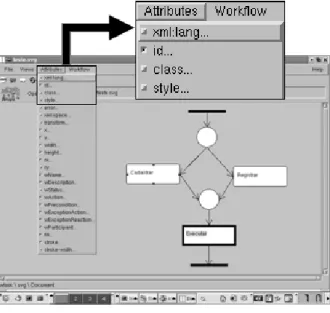
The necessity for a more generic edition came from our implementation of the Amaya Workflow (AW) editor [10][9] as seen in Figure 12. Amaya [2] is a browser/editor developed by the W3C that supports SVG, XLink, CSS and XSL languages. The AW is being adapted to provide the editing, parsing and interpretation of the GEVS languages.
Two levels of functionalities are needed to successfully adapt the AW to support generic editing.
The first level regards the support of generic editing of any GEVS visual phrase. Generic constraints and generic error verifications are being implemented, extending several others edition and visualization functionalities already implemented within Amaya’s SVG editor.
Figure 12. Amaya Workflow
The second level regards the adaptation of the edition and the interpretation processes for different visual languages in a modular way. When a user is editing a GEVS visual phrase that represents an UML class diagram, for example, he needs of different functionality from those that he needs when are editing one that represents a Petri Net.
In the thesis context, this proposal is just a preliminary result of the first year of PhD course studies, therefore several definitions, studies and implementations are needed.
9. References
[1] Adobe. SVG Zone. Available in:
http://www.adobe.com/svg/demos/main.html. Accessed in 2004.
[2] Akehurst, D. H. Model translation: A uml-based
specification technique and active implementation approach. PhD thesis, University of Kent, Canterbury, UK 2000.
[3] Brandes, U., Eiglsperger, M., Herman, I., Himsolt, M. and Scott Marshall, M.S. “GraphML Progress Report: Structural LayerProposal”. Proc. 9th Intl. Symp. Graph Drawing (GD'01). Lecture Notes in Computer Science, pp. 501-512, (c) Springer-Verlag, 2001.
[4] Holt, R. C., et.al., “GXL: Toward a Standard
Exchange Format”, in: 7th Working Conference on Reverse Engineering, IEEE Computer Society, 2000, pp. 162-171.
[5] J. Suzuki, Y. Yamamoto. Making UML models
exchangeable over the Internet with XML: The UXF Approach. In proc. of int. Workshop on UML'98, Mulhouse, France, Lecture Notes in Computer Science. Springer.
[6] Lakin, Fred, Visual Grammars for Visual Languages, Proceedings of the American Association for Artificial Intelligence, pp 683-688. Seattle, Washington, July 1987. [7] M. J¨ungel, E. Kindler, and M. Weber. The Petri net markup language. Petri Net Newsletter, 59:24–29, 2000.
[8] Sourceforce. GXL Graphpad. Disponível em:
http://gxl.sourceforge.net/index.html/ .Accessed in 2004.
[9] Telecken T. Amaya Workflow Home Page. Available
in: http://www.inf.ufrgs.br/~telecken/aw/ Access in 2004. [10] Telecken, T.L.; et al. Modeling of Courses through Workflow using the standard SVG/XML. In Proceedings of EDMEDIA'2002 World Conference on Educational Multimidia, Hipermidia & Telecomunications, Denver, USA, 2000, 24-29
[11] van der Aalst, W.M.P., et al, A.”Verification of XRL: An XML-based Workflow Language” In Proceedings of the 6th International Conference on CSCW in Design, pages 427-432. NRC Research Press, Ottawa, Canada, 2001.
[12] W3C Scalable Vector Graphics. Available in:
http://www.w3.org/Graphics/SVG/ . Accessed in 2004. [13] W3C. Extensible Markup Language (XML) Available in: http://www.w3.org/XML/. Accessed in 2004.
[14] W3C. Welcome to Amaya. Available in:
http://www.w3.org/Amaya/. Accessed in 2004.
[15] W3C. XML Accessibility Guidelines. Available in: http://www.w3.org/TR/2001/WD-xmlgl-20010829. Accessed in 2004.
[16] W3C. XML Linking Language. Available in:
http://www.w3.org/TR/xlink/. Accessed in 2004.
[17] W3C. XSL Transformations (XSLT) Version 2.0.
Available in: http://www.w3.org/TR/xslt20/.Access in 2004.
[18] XGMML. XGMML (eXtensible Graph Markup and
Modeling Language). Available in: http://www.cs.rpi.edu/~puninj/XGMML/.Access in 2004.